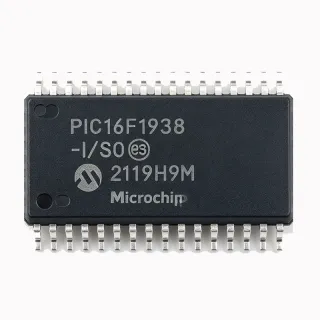
PIC18F2620-I/SO - 8-Bit 40MHz 64KB Flash MCU | Microchip
部品番号: PIC18F2620-I/SO ✓ 生産中| 数量 | 単価 | 小計 |
|---|---|---|
| 1 | $8.33 | $8.33 |
| 10 | $7.59 | $75.90 |
| 100 | $6.71 | $671.00 |
| 500 | $5.94 | $2,970.00 |
| 1,000 | $5.21 | $5,210.00 |
PIC18F2620-I/SO 概要
What is a PIC18 microcontroller? A PIC18 microcontroller (MCU) belongs to Microchip's 8-bit RISC architecture family, a category of Harvard-architecture microcontrollers that combine a C compiler-optimized instruction set, single-cycle hardware 8x8 multiplier, and on-chip nanoWatt power management for high-performance embedded control. PIC18 sits within the hierarchy: 8-bit MCU -> PIC microcontroller -> PIC18 family -> PIC18F2x20 sub-family. The nanoWatt technology grants multiple power-managed modes (Run, Idle, Sleep, and deep Sleep with RTCC), making these MCUs the conventional choice for both high-performance and power-sensitive applications.
Key features include hardware-multiplier-accelerated C-compiler-friendly architecture, internal oscillator support from 31 kHz to 8 MHz with Fail-Safe Clock Monitor (FSCM), a Watchdog Timer with separate RC oscillator, and on-chip In-Circuit Serial Programming (ICSP) via two pins. The 28-SOIC wide-body footprint gives this part a generous thermal envelope for industrial enclosures where 0.1" pitch DIP is too large but 28-SSOP/TSSOP would be too small.
Typical applications include industrial control and sensor conditioning nodes, low-cost consumer appliance controllers, automotive body and comfort modules (LIN/J2602 slaves), USB-to-UART bridge firmware, and battery-powered measurement instruments that benefit from nanoWatt sleep states. When designing, note that the 'I' suffix denotes the industrial temperature grade and 'SO' denotes the wide-body 28-pin SOIC; matching the exact designator is essential when ordering from Microchip authorized distributors.
ドロップイン代替品: PIC18F2620-I/SO — 同一パッケージでピン互換。PCBの作り直しが必要な異なるパッケージの部品は除外されています。
このシリーズのバリエーション
同一シリーズでドロップイン互換のモデル: PIC18F2620-I/SO (同一形状・フットプリント) — 相違点: Package, ADC, Timers, Program Memory (Flash), Operating Temperature.
クイック比較ツール — 並列比較する代替部品を選択:
PIC18F2525-I/SO
✅ ドロップイン✓ 在庫あり
$3.32 / 個
データシートを見る →PIC18F25K22-I/SO
✅ ドロップイン✓ 在庫あり
$1.78 / 個
データシートを見る →PIC18F25K20-I/SO
✅ ドロップイン✓ 在庫あり
$2.55 / 個
データシートを見る →PIC18F2620T-I/SO
✅ ドロップイン✓ 在庫あり
$5.4 / 個
データシートを見る →PIC18F2620-E/SO
✅ ドロップイン✓ 在庫あり
$4.21 / 個
データシートを見る →PIC18F2620-I/SO 最大定格&電気的特性
| Architecture | PIC18 8-bit RISC (Harvard) |
| Program Memory | 64 KB Flash (32K x 16 words) |
| Data SRAM | 3968 bytes |
| EEPROM | 256 bytes |
| Maximum CPU Speed | 40 MHz (10 MIPS) |
| Instruction Set | 75 instructions, 83 with extended opcode |
| Hardware Multiplier | 8 x 8 single-cycle |
| Digital I/O Pins | 25 |
| ADC | 10-bit, up to 10 channels |
| Analog Comparators | 2 |
| Timers | 2 x 8-bit, 3 x 16-bit |
| CCP Modules | 2 (Capture/Compare/PWM) |
| Communication Peripherals | EUSART (LIN/J2602), MSSP (SPI / I2C) |
| Parallel Slave Port | Yes (PORTD) |
| Internal Oscillator | 31 kHz to 8 MHz |
| Fail-Safe Clock Monitor | Yes |
| Watchdog Timer | Yes, separate RC oscillator |
| 動作温度 | -40C to +85C (industrial grade) |
| パッケージ | 28-pin SOIC (SO) wide-body |
| ICSP Programming | Yes (2-wire In-Circuit Serial Programming) |
| Self-Programmable Flash | Yes |
| Power-Saving Modes | nanoWatt: Run, Idle, Sleep, deep Sleep with RTCC |
| RoHS ステータス | Compliant |
PIC18F2620-I/SO ピン構成
| ピン 1 | RA0/AN0 — Digital I/O / Analog input 0 |
| ピン 2 | RA1/AN1 — Digital I/O / Analog input 1 |
| ピン 3 | RA2/AN2/VREF- — Digital I/O / Analog input 2 / ADC VREF- |
| ピン 4 | RA3/AN3/VREF+ — Digital I/O / Analog input 3 / ADC VREF+ |
| ピン 5 | RA4/T0CKI/C1OUT — Digital I/O / Timer0 clock / Comparator 1 output |
| ピン 6 | RA5/AN4/SS/HLVDIN/C2OUT — Digital I/O / Analog input 4 / SPI SS / HLVD / Comparator 2 output |
| ピン 7 | RE0/RD/AN5 — Digital I/O / Parallel port read / Analog input 5 |
| ピン 8 | RE1/WR/AN6 — Digital I/O / Parallel port write / Analog input 6 |
| ピン 9 | RE2/CS/AN7 — Digital I/O / Parallel port CS / Analog input 7 |
| ピン 10 | VDD — Positive supply |
| ピン 11 | VSS — Ground |
| ピン 12 | RA6/OSC2/CLKO — Digital I/O / Oscillator output / Clock output |
| ピン 13 | RA7/OSC1/CLKI — Digital I/O / Oscillator input / Clock input |
| ピン 14 | VSS — Ground (alternate) |
| ピン 15 | RC0/T1OSO/T1CKI — Digital I/O / Timer1 oscillator out / Timer1 clock |
| ピン 16 | RC1/T1OSI/CCP2 — Digital I/O / Timer1 oscillator in / CCP2 |
| ピン 17 | RC2/CCP1 — Digital I/O / CCP1 |
| ピン 18 | RC3/SCK/SCL — Digital I/O / SPI SCK / I2C SCL |
| ピン 19 | RC4/SDI/SDA — Digital I/O / SPI SDI / I2C SDA |
| ピン 20 | RC5/SDO — Digital I/O / SPI SDO |
| ピン 21 | RC6/TX/CK — Digital I/O / EUSART TX / EUSART clock |
| ピン 22 | RC7/RX/DT — Digital I/O / EUSART RX / EUSART data |
| ピン 23 | RB0/INT0/FLT0 — Digital I/O / External interrupt 0 / PWM fault |
| ピン 24 | RB1/INT1 — Digital I/O / External interrupt 1 |
| ピン 25 | RB2/INT2 — Digital I/O / External interrupt 2 |
| ピン 26 | RB3/INT3/CCP2 — Digital I/O / External interrupt 3 / CCP2 alternate |
| ピン 27 | RB4/KBI0 — Digital I/O / Interrupt-on-change 0 |
| ピン 28 | RB5/KBI1/PGM — Digital I/O / Interrupt-on-change 1 / LVP program |
| ピン 29 | RB6/KBI2/PGC — Digital I/O / Interrupt-on-change 2 / ICSP clock |
| ピン 30 | RB7/KBI3/PGD — Digital I/O / Interrupt-on-change 3 / ICSP data |
| ピン 31 | MCLR/VPP/RE3 — Master clear / Programming voltage / PORTE bit 3 |
| ピン 32 | VDD — Positive supply (alternate) |
主な用途
PIC18F2620-I/SO の用途: 6 件s: Industrial Sensor Conditioning Nodes, Automotive LIN/J2602 Slave Nodes, USB-to-UART Bridge Replacement, Battery-Powered Measurement Instrument, Consumer Appliance Controller Board, HVAC Thermostat Controller.
Industrial Sensor Conditioning Nodes
The PIC18F2620-I/SO suits industrial 4-20 mA loop-powered sensor nodes and RTU front-ends because of its 10-channel 10-bit ADC at 100 ksps, nanoWatt sleep current below 1 uA with RTCC active, and 25 I/O pins in a single 28-SOIC. The on-chip EUSART supports RS-485 half-duplex at 9-bit mode for Modbus RTU. PIC18F2620's -40C to +85C industrial temperature range and 64 KB Flash allow complete protocol stacks plus data logging. Placed on a sensor transmitter board, the MCU scans ADC inputs, applies linearization, and transmits results over RS-485. Unlike Cortex-M0+ alternatives, the PIC18F2620 draws 700 nA in deep Sleep with RTCC, enabling multi-year battery life on a single D-cell. Companion: MCP3421 18-bit ADC, MAX485 RS-485 transceiver.
おすすめ
Automotive LIN/J2602 Slave Nodes
The PIC18F2620-I/SO is the canonical Microchip MCU for LIN 1.3/2.0 and J2602 compliant automotive slave nodes used in door modules, seat controllers, mirror adjusters, and HVAC blend actuators. The enhanced EUSART with LIN hardware synchronization and auto-baud detection simplifies firmware, while 64 KB Flash holds the LIN stack plus diagnostics. PIC18F2620's industrial temperature range covers most in-cabin nodes; for under-hood ECUs use the PIC18F2620-E/SO extended grade. The 28-SOIC footprint fits dense PCBAs behind door trim. Place on a body-control module: the MCU receives LIN frames from the master, drives power MOSFETs, and replies with sensor data. Compared to a UART-only MCU, the on-chip LIN engine eliminates interrupt overhead and improves baud-rate tolerance to ±14%.
おすすめ
USB-to-UART Bridge Replacement
The PIC18F2620-I/SO is a cost-effective replacement for legacy USB-to-UART bridge ICs when firmware adds CDC ACM over a companion USB transceiver such as MCP2200 or MCP2221A. The 10 MIPS PIC18F2620 throughput handles full-speed USB polling at 1 kHz with adequate headroom, and the MSSP plus EUSART can manage secondary SPI/I2C peripherals. The 28-SOIC package fits standard bridge form factors, and 64 KB Flash allows flexible CDC ACM firmware plus vendor-specific commands. Compared to dedicated USB-UART bridges, the PIC18F2620 approach offers user-customizable baud tables, GPIO breakouts, and bootloader upgrade paths. Note: PIC18F2620 does not contain native USB - a discrete USB transceiver is required.
おすすめ
Battery-Powered Measurement Instrument
The PIC18F2620-I/SO is well-suited to handheld DMMs, clamp meters, and portable data loggers where 10 MIPS performance and microamp sleep current must coexist. PIC18F2620's nanoWatt technology draws 100 nA in Sleep mode and 700 nA in deep Sleep with RTCC, enabling 2000+ hour battery life on two AA cells. The 10-bit ADC, dual comparators, and 5 timers let a single MCU measure voltage, current, frequency, and temperature sequentially. Place on the meter mainboard: PIC18F2620 powers up to take a measurement, drives the LCD via I/O expansion, and returns to Sleep. Compared to the Microchip PIC18F25K22 with XLP, the PIC18F2620 sleep current is higher, but its larger 64 KB Flash accommodates full data-logging firmware and user-interface code.
おすすめ
Consumer Appliance Controller Board
The PIC18F2620-I/SO is widely deployed in white-goods controllers such as washing machines, dishwashers, and induction cooktops where 25 I/O pins drive relays, triacs, keypads, and seven-segment displays. PIC18F2620's 64 KB Flash fits complex state machines for wash cycles, while the 10 MIPS throughput keeps AC zero-crossing interrupts responsive. The 28-SOIC wide-body package handles the 105C ambient of appliance cabinets. Place on the appliance mainboard: the MCU reads temperature sensors, controls motor direction via H-bridge, sequences water valves, and manages user inputs. Compared to an 8051 alternative, the PIC18F2620 C-compiler-friendly instruction set reduces firmware development time by 30-40%.
おすすめ
HVAC Thermostat Controller
The PIC18F2620-I/SO works well as the core MCU of a 7-day programmable thermostat controlling single-stage cooling, multi-stage heating, fan, and humidifier. The 10-bit ADC reads thermistor temperature with adequate resolution, while 64 KB Flash stores programmable profiles. PIC18F2620's low-power Sleep modes let the thermostat run for one year on 24 VAC common wire without brown-out. The 28-SOIC footprint fits standard 4-inch thermostat bases. Place on the wall plate: PIC18F2620 schedules temperature setpoints, drives the LCD, controls HVAC outputs, and wakes periodically for display updates. Compared to discrete logic controllers, the PIC18F2620 enables remote sensor averaging, adaptive recovery, and Wi-Fi add-on modules.
おすすめ
おすすめ製品の概要
エンジニアリング参考データ: PIC18F2620-I/SO — 比較、設計ガイダンス、コンプライアンス情報。
選定ガイド
代替品との比較
| パラメータ | この製品 | PIC18F2525-I/SO | PIC18F25K22-I/SO | PIC18F25K20-I/SO | PIC18F2620T-I/SO | PIC18F2620-E/SO |
|---|---|---|---|---|---|---|
| Package | 28-SOIC (wide-body, SO) | 28-SOIC (wide-body, SO) | 28-SOIC (wide-body, SO) | 28-SOIC (wide-body, SO) | 28-SOIC (wide-body, SO) | 28-SOIC (wide-body, SO) |
| Brand | Microchip Technology | Microchip Technology | Microchip Technology | Microchip Technology | Microchip Technology | Microchip Technology |
| Flash Program Memory | 64 KB | 24 KB (-62%) | 32 KB (-50%) | 32 KB (-50%) | 64 KB (identical) | 64 KB (identical) |
| SRAM | 3968 bytes | 3968 bytes | 1536 bytes (-61%) | 1536 bytes (-61%) | 3968 bytes (identical) | 3968 bytes (identical) |
| EEPROM | 256 bytes | 256 bytes | 256 bytes | 256 bytes | 256 bytes (identical) | 256 bytes (identical) |
| Maximum CPU Speed | 40 MHz (10 MIPS) | 40 MHz (10 MIPS) | 64 MHz (16 MIPS) | 64 MHz (16 MIPS) | 40 MHz (10 MIPS) | 40 MHz (10 MIPS) |
| ADC | 10-bit, 10 channels | 10-bit, 10 channels | 10-bit, 12 channels | 10-bit, 11 channels | 10-bit, 10 channels | 10-bit, 10 channels |
| Operating Temperature | -40C to +85C (industrial) | -40C to +85C | -40C to +85C | -40C to +85C | -40C to +85C | -40C to +125C (extended) |
| Power-Saving Modes | nanoWatt (Run/Idle/Sleep) | nanoWatt | nanoWatt XLP | nanoWatt XLP | nanoWatt | nanoWatt |
| EUSART (LIN/J2602) | Yes (enhanced) | Yes (enhanced) | Yes | Yes | Yes (identical) | Yes (identical) |
主な差別化要因
- Largest Flash in the 28-SOIC PIC18F2x2x family (vs PIC18F2525-I/SO)
- LIN/J2602 automotive headroom (vs PIC18F25K22-I/SO)
- Extended temperature grade availability (vs PIC18F2620T-I/SO)
設計ノート
The PIC18F2620-I/SO in 28-SOIC wide-body has a thermal resistance of approximately 50 C/W theta_JA (estimated, based on standard SOIC-28 wide-body thermal data; verify with the Microchip 39631F datasheet section 'Thermal Specifications'). For a 5V design with 25 mA active CPU current, dissipation is approximately 125 mW, yielding a 6C junction rise above ambient - well within industrial limits. If the application uses 25 mA active + peripheral current, the MCU itself does not require a heatsink. Provide at least 0.5 square inches of ground-plane copper beneath the package to keep die temperature under 70C inside an enclosed 85C ambient.
Power decoupling: place a 100 nF ceramic capacitor as close as possible to each VDD pin (28-SOIC has two VDD pins at pin 10 and pin 32). Add a single 10 uF bulk capacitor on the same PCB node for ADC reference stability. For battery-powered applications using nanoWatt Sleep, the PIC18F2620 draws approximately 100 nA in Sleep and 700 nA in deep Sleep with RTCC active (estimated from Microchip nanoWatt specification family typicals). Disconnect unused analog inputs via the CMCON register to eliminate parasitic current paths, and set unused I/O pins as outputs low to avoid floating CMOS input current.
Crystal placement and routing are critical for PIC18F2620 designs. Place the crystal or resonator within 10 mm of OSC1/CLKI (pin 13) and OSC2/CLKO (pin 12), and route the traces symmetrically. Keep the crystal ground trace short to the nearest VSS pin (pin 11 or pin 14). Add 4.7 kohm to 10 kohm loading resistors on each side of the crystal only if needed for low-frequency crystals; the internal oscillator (31 kHz to 8 MHz) eliminates this requirement for many designs. Keep the crystal traces away from switching power and high-current traces to avoid injection of clock noise.
Common PIC18F2620 design pitfalls: (1) Failing to configure the MCLR pin correctly - if MCLR is unused, connect it to VDD through a 10 kohm resistor; tying it directly to VDD without a resistor can prevent in-circuit serial programming. (2) Enabling ICSP via PGC/PGD (pins 27/29) requires 4.7 kohm pull-downs on these lines if they are shared with user I/O, otherwise the programmer cannot reliably drive the lines. (3) The PIC18F2620 does not include native USB - do not assume USB capability from the silicon; an external USB transceiver is required. (4) Setting configuration bits requires careful attention to the __CONFIG macro in the C header; a wrong FOSC setting can lock the device.
For LIN/J2602 bus applications using the PIC18F2620 EUSART, the bus capacitance should be below 2 nF per node to maintain baud-rate timing margins. Add a 1 kohm pull-down on the LIN bus to keep it recessive when the transceiver is disabled. For I2C bus designs, ensure pull-ups are sized correctly - typical 4.7 kohm at 100 kHz, 2.2 kohm at 400 kHz. The MSSP peripheral supports both 100 kHz Standard and 400 kHz Fast modes, but not 1 MHz Fast-mode Plus. For ADC accuracy, bypass the VREF+ pin with a 100 nF ceramic and a 10 uF tantalum if external VREF is used.
コンプライアンス情報
RoHS compliant per Microchip product page. AEC-Q100 qualification status not specifically stated for the 28-SOIC variant; PIC18F2620 family parts are widely deployed in non-safety-critical automotive body modules.