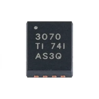
TUSB214RWBR - USB 2.0 HS Signal Conditioner | Texas Instruments
部品番号: TUSB214RWBR ✓ 生産中TUSB214RWBR 概要
A USB signal conditioner is an interface IC that compensates for attenuation, distortion, and timing degradation introduced by connectors, cables, PCB traces, and other interconnect elements. Positioned within the broader USB interface hierarchy, it sits between a USB host or device controller and a physical USB connection. Its DC boost function helps maintain usable signal amplitude through lossy channels, while its integrated charging-port controller simplifies compliance with BC1.2 downstream-port requirements.
The TUSB214 supports LS, FS, and HS signaling and provides selectable signal gain for high-loss applications. Its D1P/M and D2P/M inputs are interchangeable, allowing the same device-oriented layout to work in host or device applications. The device also supports daisy-chain operation, which can simplify cascading through multiple lossy cable or connector sections when a single conditioner is not sufficient.
The BC1.2 charging function is configurable through a pin strap or I2C. This provides a practical choice between hardware-configured designs and firmware-controlled implementations. The TUSB214 additionally features very low USB disconnect and shutdown power consumption, making it suitable for power-conscious USB equipment where inactive-state leakage can influence battery life or system thermal performance.
Typical applications include USB 2.0 peripheral connections, host-to-cable interfaces, device-to-cable interfaces, and systems that require an integrated downstream charging-port controller. It is particularly useful when PCB routing, connector transitions, or cable loss could degrade high-speed USB data. The 1.6 mm by 1.6 mm X2QFN footprint supports compact designs, although its fine pitch requires careful layout, assembly, and inspection practices.
The principal design consideration is placement. The conditioner should be positioned near the loss or connector transition it is intended to correct, while its data traces should remain short, properly terminated, and routed away from noisy power or high-current paths. Designers should also confirm the configured BC1.2 mode, enable state, and signal-gain setting against the final system behavior.
This product page combines the TUSB214 family characteristics with package-specific ordering information, application guidance, drop-in alternatives, and a practical comparison framework. It is intended to support component selection and board-level implementation decisions rather than simply repeat the basic catalog description.
ドロップイン代替品: TUSB214RWBR — 同一パッケージでピン互換。PCBの作り直しが必要な異なるパッケージの部品は除外されています。
TUSB214IRWBR
✅ ドロップイン📋 参考代替品(カタログ未掲載)
TUSB214QRWBRQ1
✅ ドロップイン📋 参考代替品(カタログ未掲載)
TUSB214QRWBTQ1
✅ ドロップイン📋 参考代替品(カタログ未掲載)
TUSB214RWBT
✅ ドロップイン価格はお問い合わせください
データシートを見る →TUSB214RWB
✅ ドロップイン ⚠️ 仕様未検証📋 参考代替品(カタログ未掲載)
TUSB214RWBR 仕様
| Product Type | USB 2.0 high-speed signal conditioner with integrated BC1.2 CDP controller |
| USB Compatibility | USB 2.0, OTG 2.0, and BC1.2 |
| Supported USB Speeds | Low speed, full speed, and high speed |
| Supply Voltage Range | 3 V to 3.6 V |
| Maximum Data Rate | 480 Mbps |
| 電源電流 | 30 mA |
| 動作温度範囲 | 0 °C to +70 °C |
| パッケージ | 12-pin X2QFN (RWB), 1.6 mm x 1.6 mm |
| 実装タイプ | Surface mount |
| Charging-Port Standard | BC1.2 Charging Downstream Port |
| BC1.2 Configuration | Pin strap or I2C configurable |
| Signal Gain | Selectable |
| Data-Pair Compatibility | D1P/M and D2P/M interchangeable |
| Host or Device Operation | Host and device agnostic |
| Daisy-Chain Support | Supported |
| Maximum Pre-Channel Length | 5 m |
| Maximum Post-Channel Length | 2 m |
| Power Consumption | Ultra-low USB disconnect and shutdown power consumption |
| RoHS ステータス | Compliant |
| Termination Count | 12 terminations |
TUSB214RWBR 12-pin x2qfn (rwb), 1.6 mm x 1.6 mm ピン配置ガイド
TUSB214RWBR (12-pin x2qfn (rwb), 1.6 mm x 1.6 mm パッケージ) のピン配置。 ピン番号、機能、接続図はメーカーのデータシートで定義されています。正確なフットプリントとはんだ付けのガイドラインについては、データシートを参照してください。

詳細なピン配置データはありません: TUSB214RWBR.
詳細は データシート をご参照ください。
主な用途
TUSB214RWBR の用途: 7 件s: USB 2.0 Host-to-Device Redriver, USB 2.0 Device-to-Host Interface, BC1.2 Charging Downstream Port, High-Loss Cable and Connector Compensation, USB OTG 2.0 Interface Conditioning, Compact Portable USB Equipment, Low-Power USB Port Front End.
USB 2.0 Host-to-Device Redriver
The TUSB214RWBR fits between a USB host controller and a connector when traces or cabling threaten high-speed signal integrity. Its 480 Mbps capability covers USB 2.0 high-speed signaling, while DC boost and selectable gain help recover signal amplitude after lossy interconnect. The interchangeable D1P/M and D2P/M inputs also support layouts that do not maintain a fixed orientation. Place the conditioner close to the channel transition, observe recommended high-speed routing practices, and verify eye margin at the receiver with the final cable and connector.
USB 2.0 Device-to-Host Interface
The TUSB214RWBR can condition a USB 2.0 device connection without tying the implementation to only host or only device signal orientation. Its host and device agnostic operation, combined with interchangeable data inputs, allows reuse of the same small-footprint circuit across multiple product variants. DC boost addresses amplitude loss while the 3 V to 3.6 V operating range aligns with conventional USB interface power rails. Designers should confirm termination behavior, enable sequencing, and BC1.2 configuration against the selected USB controller and product requirements.
BC1.2 Charging Downstream Port
The TUSB214RWBR is appropriate for a downstream USB port that must combine signal conditioning with BC1.2 charging behavior. Its integrated Charging Downstream Port controller can be configured by pin strap for a straightforward implementation or through I2C when software control is preferred. Supporting up to 480 Mbps preserves USB 2.0 high-speed operation alongside charging functionality. The circuit must still implement the required USB power, data, advertisement, and connection behavior defined by the BC1.2 system design.
High-Loss Cable and Connector Compensation
The TUSB214RWBR addresses high-loss USB paths where connectors, cable transitions, or PCB routing reduce signal quality. Selectable gain, DC boost, and daisy-chain capability allow designers to address channels that are more degraded than a short board-level connection. The manufacturer supports pre-channel and post-channel arrangements of up to 5 m and 2 m, respectively, subject to the complete channel design. Validate eye diagrams, compliance masks, and inter-pair skew after integrating the actual cable, connector, shielding, and enclosure.
USB OTG 2.0 Interface Conditioning
The TUSB214RWBR can support USB OTG 2.0 interface paths because it explicitly supports OTG 2.0 alongside USB 2.0 and BC1.2. Its host and device agnostic behavior is useful for product designs in which a single physical interface must accommodate different connection roles. The small 1.6 mm by 1.6 mm X2QFN package also leaves board area for portable or compact systems. OTG role negotiation remains a system-level function and must be implemented in the controller or system firmware.
Compact Portable USB Equipment
The TUSB214RWBR suits compact portable equipment that uses USB 2.0 high-speed data and benefits from ultra-low disconnect and shutdown power consumption. Its 30 mA specified operating supply current and 3 V to 3.6 V supply range support integration into conventional embedded power systems. The 12-pin X2QFN package minimizes occupied board area, although the 1.6 mm by 1.6 mm footprint requires fine-pitch assembly capability. Battery-life calculations should include system-specific idle, suspend, and shutdown behavior rather than relying only on the operating current.
Low-Power USB Port Front End
The TUSB214RWBR is useful as a USB port front end where inactive-state power is important. Its ultra-low USB disconnect and shutdown power consumption helps reduce the burden on the system power rail when the port is not actively transferring data. The device preserves low-, full-, and high-speed support up to 480 Mbps and integrates BC1.2 capability, allowing one compact component to handle both channel conditioning and charging-port signaling. Verify the actual disabled-state current and enable sequence in the final power architecture.
エンジニアリング参考データ: TUSB214RWBR — 比較、設計ガイダンス、コンプライアンス情報。
選定ガイド
代替品との比較
| パラメータ | この製品 | TUSB214IRWBR | TUSB214QRWBRQ1 | TUSB214QRWBTQ1 | TUSB214RWBT | TUSB214RWB |
|---|---|---|---|---|---|---|
| Package | 12-X2QFN (RWB), 1.6 mm x 1.6 mm | 12-X2QFN (RWB), 1.6 mm x 1.6 mm | 12-X2QFN (RWB), 1.6 mm x 1.6 mm | 12-X2QFN (RWB), 1.6 mm x 1.6 mm | 12-X2QFN (RWB), 1.6 mm x 1.6 mm | 12-X2QFN (RWB), 1.6 mm x 1.6 mm |
| Brand | Texas Instruments | Texas Instruments | Texas Instruments | Texas Instruments | Texas Instruments | Texas Instruments |
| Function | USB 2.0 high-speed signal conditioner with DC boost and integrated BC1.2 CDP | TUSB214-family USB 2.0 high-speed signal conditioner | Automotive-orderable TUSB214-family USB 2.0 high-speed signal conditioner | Automotive-orderable TUSB214-family USB 2.0 high-speed signal conditioner | TUSB214-family USB 2.0 high-speed signal conditioner | TUSB214-family USB 2.0 high-speed signal conditioner |
| BC1.2 Support | Integrated BC1.2 CDP with pin-strap or I2C configuration | TUSB214-family BC1.2 support | TUSB214-family BC1.2 support | TUSB214-family BC1.2 support | TUSB214-family BC1.2 support | TUSB214-family BC1.2 support |
| Signal Gain and DC Boost | Selectable gain and DC boost supported | TUSB214-family gain and DC-boost functions | TUSB214-family gain and DC-boost functions | TUSB214-family gain and DC-boost functions | TUSB214-family gain and DC-boost functions | TUSB214-family gain and DC-boost functions |
主な差別化要因
- Integrated BC1.2 charging functionality in the signal-conditioning device (vs TUSB214IRWBR)
- Commercial-temperature ordering option in the same compact footprint (vs TUSB214QRWBRQ1)
- DC boost, selectable gain, and daisy-chain support in one USB interface IC (vs TUSB214RWB)
設計ノート
Place the TUSB214RWBR near the connector, cable transition, or other discontinuity that causes signal degradation. Keep D+ and D+ pairs, and D- and D- pairs, routed together with tightly matched geometry, continuous reference planes, and no unnecessary stubs. Follow the manufacturer recommended layout for high-speed differential routing and validate the complete channel because nominal trace length alone does not establish USB eye margin.
Do not select a replacement solely because it uses a similar X2QFN package. Verify every power, data, enable, strap, and I2C connection against the TUSB214 datasheet and confirm the exact ordering suffix. The RWBR variant is specified for 0 °C to +70 °C, while Q1 and other suffixes may carry different environmental or qualification requirements. A valid PCB reuse decision requires both footprint and functional-pin compatibility.
Operate the device from its specified 3 V to 3.6 V supply range and provide low-impedance decoupling close to the supply pins. Account for the specified 30 mA operating current plus the load presented by the connected USB interface and downstream charging function. Confirm the system enable and shutdown states because ultra-low disconnect and shutdown consumption can only reduce total power when the external circuitry places the device in those states correctly.
Validate USB 2.0 high-speed performance with the intended cable, connector, PCB stack-up, and adjacent switching noise in the assembled system. Inspect eye diagrams, differential impedance, skew, and common-mode behavior at the receiver rather than relying only on the 480 Mbps signaling label. If attenuation is severe, use the selectable-gain and daisy-chain features only after confirming that gain configuration will not cause over-amplification or timing distortion.
コンプライアンス情報
The TUSB214RWBR listing identifies the exact component as RoHS compliant. The standard RWBR ordering option is not identified as automotive-qualified; the Q1 family variants are designated for automotive use. REACH, lead-free, halogen-free, and conflict-minerals status are not established by the available component listings.