모터 드라이버
제품 (261)

AMIS30522C522 - 800mA Micro-Step Stepper Motor Driver | onsemi
The onsemi AMIS30522C522 is a 32-NQFP (7x7 mm) micro-stepping bipolar stepper motor driver delivering up to 800 mA per phase, SPI configurable for embedded system integration, and qualified for industrial and automotive applications including body and chassis systems. An stepper motor driver is an integrated power and logic IC that converts step/direction commands from a host microcontroller into precisely controlled current in each winding of a two-phase bipolar stepper motor. It sits inside the motor-control subsystem hierarchy: stepper motor driver -> motor driver -> motor control -> power management -> semiconductor. The AMIS30522C522 is part of the onsemi AMIS-30522/NCV70522 family and uses I2T100 high-voltage mixed-signal technology so analog power stages and digital control logic coexist on a single die. Key features of the AMIS30522C522 include a current-translation table for microstepping, on-chip 5 V regulator to supply external microcontrollers, programmable peak current up to 800 mA per phase, programmable slow/fast decay and PWM frequencies, integrated charge pump for the high-side transistors, SPI control interface plus dedicated step (NXT) and direction (DIR) input pins, and a watchdog reset output. The chip operates across the full automotive battery range. The integrated charge pump and bootstrap diodes minimize external component count, allowing compact PCB designs. Architecturally, the AMIS30522C522 uses a dual H-bridge power MOSFET output stage to drive both phases of a bipolar stepper with synchronous rectification. The current regulation loop runs from a sense resistor and an internal DAC reference. Microstepping is achieved via a sine-cosine weighted current-translation table, while commands integrate directly through a single NXT clock pin per step. This produces smoother rotation than full- or half-step drivers at the cost of higher switching loss. Typical applications for the AMIS30522C522 are HVAC flap and valve actuators, instrument cluster gauges, headlight leveling mechanisms, throttle-by-wire positioning, general-purpose automation stepper drives, and laboratory instrumentation. The integrated voltage regulator and watchdog simplify host MCU integration. The NQFP-32 package is suitable for both hand-soldered prototypes and high-volume automotive SMT lines. Designers should ensure adequate heatsinking because the chip can dissipate several watts at 800 mA output. Add bulk reservoir capacitors at the motor supply pin (VMOT) to absorb back-EMF, and keep the analog/digital ground returns short or the impact of motor inrush will be visible on the logic supply. The AMIS-30522 product page lists automotive-grade NCV-prefixed variants for the same lifecycle - choose NCV for automotive-qualified designs. This page synthesizes distributor pricing, drop-in alternatives, and SPI configuration notes that go beyond the manufacturer datasheet - including package-level details, microstep programming references, and practical decoupling guidance.

AMIS30542 - Micro-Stepping Stepper Motor Driver | onsemi
The onsemi AMIS30542 (AMIS-30542) is a micro-stepping stepper motor driver for bipolar stepper motors, integrating dual H-bridge power MOSFETs, an SPI-configurable micro-stepping controller, and an on-chip 5 V regulator in a single 32-lead NQFP (7x7 mm) package. The device delivers up to 1500 mA RMS phase current per coil, supports 4-bit micro-stepping up to 1/32-step resolution, and operates from a wide 6 V to 30 V motor supply with logic-compatible 3.3 V / 5 V I/O. A stepper motor driver is a power-management IC that translates low-power step/direction commands from a microcontroller into the high-current, sequenced phase currents needed to rotate a bipolar stepper motor by a precise mechanical increment. In the broader power-management hierarchy, stepper drivers sit below general motor drivers and above simple MOSFET H-bridges, combining power-stage, current-sense, and motion-control logic in one IC. The micro-stepping category adds sinusoidal current shaping so each full step is divided into smaller sub-steps, eliminating resonance, reducing audible noise, and improving positional accuracy. Key features of the AMIS30542 include active fly-back diodes (eliminating external recirculation diodes in most applications), integrated thermal warning and thermal shutdown, full output short-to-ground/short-to-supply protection and open-load diagnostics, and a dedicated "speed and load angle" (SLA) pin that provides real-time back-EMF feedback for stall detection or torque monitoring. Communication to the host MCU is handled through a standard 4-wire SPI interface for current limit, micro-step resolution, decay mode, and direction configuration. The internal architecture uses a mixed-signal controller with a programmable current-translation table, dual DMOS H-bridges, and a charge-pump gate supply for the high-side N-channel FETs. The integrated 5 V LDO can supply an external microcontroller (up to 50 mA typical), and the dedicated reset/watchdog block simplifies system design for automotive and industrial mechatronic modules. Typical applications include automotive headlamp leveling and adaptive front lighting, HVAC damper and valve actuators, industrial CNC feeder axes, 3D printer and labeling machine stepper axes, robotics joint actuation, and medical infusion-pump drives. The wide operating voltage range and on-chip diagnostics make the part particularly well-suited to 12 V/24 V automotive and industrial environments. When designing with this part, ensure the SLA pin is correctly decoded to avoid false stall events at low speeds. The integrated charge pump requires external flying capacitors (Ccp1, Ccp2) and a reservoir capacitor on VCP, which must be placed close to the IC. Always respect the maximum phase current of 1500 mA RMS and provide adequate PCB copper for thermal dissipation - the exposed thermal pad must be soldered to a ground copper pour. This page synthesizes distributor pricing, verified drop-in alternatives, and practical design notes not found in the manufacturer datasheet alone.

AMIS30542C5421G - 3.2A Bipolar Stepper Motor Driver, SPI, NQFP-32
The onsemi AMIS30542C5421G is a micro-stepping stepper motor driver for bipolar stepper motors, rated up to 3.2 A coil current, in a 32-pin NQFP (7x7 mm) package, with an SPI control interface. According to the manufacturer datasheet, the part integrates two H-bridge power MOSFET outputs, an SPI-configurable current-translation table, on-chip 5 V regulator, reset output, and watchdog reset for the host microcontroller. The device operates from a nominal 12 V motor supply (range varies by load) and supports micro-stepping up to 1/32 step resolution via SPI-programmable current levels. A bipolar stepper motor driver is an H-bridge driver IC specifically designed to commutate two-winding (bipolar) stepper motors by reversing current direction in each coil pair. The AMIS-30542 sits inside the broader motor-control hierarchy: stepper driver -> motor driver -> motion control IC -> power management & motor-driver semiconductor. By generating precisely controlled sinusoidal current waveforms in each phase, micro-stepping drivers eliminate the resonance and torque ripple of full-step operation, enabling smooth, low-noise motion for positioning applications. Key features include 3.2 A maximum coil current, integrated dual H-bridge power MOSFETs, SPI programmable micro-stepping mode, on-chip voltage regulator, hardware watchdog reset, over-current protection, and over-temperature shutdown. The current-translation table takes the next micro-step from an external step clock, offloading trajectory computation from the host MCU. The 32-NQFP package exposes all motor, supply, and digital pins for easy PCB routing in industrial and automotive motion subsystems. Typical applications include automotive HVAC flap motors, headlight beam leveling, dashboard gauge pointers, industrial fluid-handling pumps, valve positioning, 3D printers, and textile machines. The SPI interface simplifies integration with small microcontrollers that lack dedicated stepper peripherals, while the watchdog ensures deterministic recovery from host firmware faults in safety-relevant systems. When designing with the AMIS-30542, place low-ESR ceramic bypass capacitors on VM and VCC, route motor outputs as short and wide as possible to limit ringing, and ensure the exposed thermal pad is soldered to a sufficiently large copper pour for the expected continuous coil current. The SPI bus should be protected with proper pull-ups and ESD diodes in harsh environments.

AMT49413 - 3-Phase BLDC Controller and MOSFET Driver | Allegro
The Allegro MicroSystems AMT49413 is a 3-phase brushless DC (BLDC) motor controller and gate driver for external N-channel MOSFET bridges, available in a 48-pin QFN-EP (7x7) package with exposed thermal pad. Key specifications include operation from 5.5 V to 50 V supply (functional guarantee down to 5.5 V), integrated commutation logic using Hall-effect sensor inputs, fixed-frequency pulse-width modulation (PWM), and gate drive capability of greater than 10 V VGS at supplies as low as 7 V. A brushless DC motor controller is an integrated circuit that handles the commutation timing and current regulation for a 3-phase brushless motor. It sits hierarchically between the gate driver and the higher-level microcontroller (MCU) within the broader motor control subsystem. The AMT49413 combines the controller, current-sense amplifier, and gate driver into a single IC, reducing external component count and PCB area compared to discrete implementations. Key features include 100% duty cycle operation for high-speed running, synchronous rectification for reduced power dissipation, and internal current sensing with an external sense resistor. The device integrates a charge pump for the high-side gate drive, eliminating the need for an external bootstrap capacitor in many topologies. Programmable features include current-limit threshold, PWM frequency, and dead time. Typical applications include automotive cooling fans, fuel and water pumps, electric power steering systems, industrial pumps and blowers, HVAC equipment, and 48 V mild-hybrid auxiliary drives. The 50 V absolute maximum rating targets 12 V and 24 V automotive buses with transient headroom. Design tip: External MOSFET selection must consider SOA at the commutation frequency chosen; switching losses scale with fSW. The exposed thermal pad must be soldered to a sufficient copper pour (recommended 1 square inch minimum) to keep junction temperature within ratings at high continuous current.
AMT49413GEVATR - 3-Phase BLDC MOSFET Controller | Allegro
The Allegro MicroSystems AMT49413GEVATR is a 3-phase brushless DC (BLDC) motor controller and gate driver for external N-channel power MOSFETs, housed in a 48-lead QFN (7x7) package with exposed thermal pad. Designed for automotive and industrial motion control, it integrates commutation logic, fixed-frequency PWM current control, and Hall-effect sensor inputs in a single IC. Operating over a wide supply range, it drives the three half-bridges of an external MOSFET bridge for high-current BLDC motors. A BLDC motor controller is a type of motor driver IC that sequentially switches the phases of a brushless DC motor using Hall-sensor feedback to determine rotor position. The controller belongs to the broader family of motor / motion controllers, which sit within the power management IC hierarchy and form the bridge between low-power logic (microcontroller, MCU) and high-current power stages (MOSFETs, IGBTs). In the system hierarchy: BLDC controller -> motor driver -> motion controller -> power management IC -> semiconductor. BLDC motors offer higher efficiency, longer life, and lower acoustic noise than brushed DC motors, making them preferred for fans, pumps, e-bikes, and EV traction auxiliaries. Key features include integrated Hall-sensor inputs, adjustable current limit, direction and run/stop control, synchronous rectification PWM for reduced switching loss, and thermal shutdown protection. The exposed thermal pad (QFN-EP) enables direct PCB heatsinking for high-current continuous operation. Fault outputs and a serial interface are provided for MCU supervision. The 48-QFN package achieves a compact footprint suitable for space-constrained motor-drive boards. The AMT49413 uses a fixed-frequency PWM architecture with built-in dead-time generation and shoot-through protection for the external N-channel FET bridge. According to the Allegro datasheet, the PWM input can be used to provide speed and torque control, and current is regulated via an external sense resistor. The 48-QFN-EP package exposes the die to the PCB copper pour, allowing sustained high-current switching without an external heatsink. Typical applications include automotive coolant pumps, HVAC fans, e-bike traction motors, industrial blowers, robotics actuators, and white-goods compressors. The wide operating voltage range and integrated protection features suit 12V/24V/48V battery-powered systems. When designing with this device, ensure the exposed pad is soldered to a sufficiently large copper pour (>=1 sq inch) to keep junction temperature within ratings at peak motor current.
AMT49413GEVATR - 50V Brushless DC Motor Driver IC | Allegro | 48-QFN
The Allegro MicroSystems AMT49413GEVATR is a three-phase brushless DC (BLDC) motor controller IC that operates from a 5.5V to 50V supply and drives N-channel external power MOSFETs in a 48-pin QFN-EP (7x7 mm) package with an exposed thermal pad. It uses a proprietary sensorless BEMF sensing scheme to commutate the motor without Hall-effect sensors, reducing BOM cost and improving reliability in dusty or high-vibration environments. The device is the commercial-grade counterpart to Allegro's AEC-Q100-qualified A4931/A49413 automotive family, delivering equivalent control performance for industrial, appliance, and white-goods applications. A Brushless DC (BLDC) motor driver is an integrated power-electronics subsystem that converts DC bus voltage into three-phase PWM waveforms timed by the rotor's electrical position, providing higher efficiency, longer life, and lower acoustic noise than brushed DC motors. BLDC motor drivers belong to the broader hierarchy: motor driver -> power management IC -> semiconductor. The AMT49413 integrates the control logic, gate drivers, current-sense amplifier, and protection blocks that previously required a discrete MCU plus FET bridge. Key specifications include a 50V absolute maximum supply rating, integrated 5V LDO for logic supply, programmable PWM frequency, soft-start, cycle-by-cycle current limiting, fault output, and thermal shutdown. The 48-QFN-EP package provides an exposed pad that lowers junction-to-ambient thermal resistance to about 28 C/W on a 4-layer 1-oz PCB, supporting continuous output currents up to several amps depending on the external MOSFET selection. The AMT49413 uses Allegro's synchronous rectified sensorless control architecture with adjustable lead angle and dynamic overcurrent thresholds. Its bootstrap-based high-side gate driver supports 100% duty-cycle operation, eliminating the audible motor-tick that plagues 6-step commutation schemes during low-speed PWM. The IC accepts a speed command from a 0-5V analog input or external PWM and outputs a tachometer (FG) signal and direction (RD) flag for closed-loop feedback. Typical applications include sensorless BLDC fans and pumps, appliance motors (washing-machine drain pumps, dishwasher circulation pumps, refrigerator compressors), HVAC blowers, and small industrial drives. The wide 5.5V-50V input range allows direct connection to 12V, 24V, and 36V battery rails without pre-regulation. When designing with the AMT49413GEVATR, pair the IC with N-channel MOSFETs whose drain-source voltage rating exceeds the maximum DC bus by at least 30% (i.e., >=75V for a 50V bus), and place the bootstrap capacitors close to the BST-CPHx pin pairs. Verify that the chosen MOSFET's total gate charge (Qg) does not push the internal regulator below the bootstrap refresh threshold at the chosen PWM frequency. This page synthesizes distributor pricing, drop-in alternatives, and practical design notes not found in the manufacturer datasheet alone, giving procurement and design engineers a single source for the AMT49413GEVATR.
BTM9011EPXUMA1 - 10A Full-Bridge Motor Driver, 7-18V | Infineon
The Infineon BTM9011EPXUMA1 is a 10 A full-bridge motor driver IC with integrated power MOSFETs and SPI interface, housed in a 14-pin PG-TSDSO-14 package with exposed pad for enhanced thermal performance. The device integrates a monolithic BCD (Bipolar-CMOS-DMOS) full-bridge designed for automotive motor drive applications such as door locks, latches, and small DC brushed-motor loads. A full-bridge motor driver IC (also known as an H-bridge) is a topology that uses four switching elements arranged in an H configuration to drive a DC or bipolar stepper motor in both directions from a single supply rail. The full-bridge sits within the broader hierarchy: motor driver IC -> motion controller -> power management IC -> semiconductor. By integrating the four MOSFETs plus gate drive, charge pump, current sense, and protection into one monolithic die, the BTM9011EPXUMA1 eliminates dozens of discrete components that an equivalent discrete solution would require. Key features include a typical path resistance of 175 mΩ at 25 °C, pulse current capability of 5.2 A for tpulse ≤ 1 s at 85 °C (4.2 A for tpulse ≤ 10 s at 85 °C), a normal supply voltage range of 7 V to 18 V with an extended range of 4.5 V to 40 V, and a minimum current limitation. PWM operation is supported up to 20 kHz. The SPI interface enables diagnostic readout and parameter configuration, while the integrated protection set includes overtemperature, overcurrent, and undervoltage lockout. The device is implemented in BCD technology and qualified to AEC-Q100 for automotive use. Compared with discrete MOSFET bridges, the integrated full-bridge cuts PCB area by roughly 60%, reduces parasitic loop inductance, and simplifies EMI compliance thanks to tighter gate-driver timing and shorter power paths. Typical applications include automotive door-lock actuators, trunk latches, fuel-flap actuators, seat adjusters, mirror-fold motors, and HVAC flap control. The combination of 10 A current limit, 20 kHz PWM, and SPI diagnostics makes the part well suited to body-electronics modules that must report fault status to a central ECU. When designing with this part, place a low-ESR 100 nF + 10 µF ceramic bypass on VS as close to the IC as possible, and tie the exposed pad to a continuous ground copper pour of at least 100 mm² to stay within the thermal envelope at full 10 A load. The SPI bus should be pulled up to VIO and isolated from the motor phase traces with a ground guard ring to avoid conducted-noise coupling during PWM transitions.
BTM9020EPXUMA1 - Full-Bridge 20A Motor Driver IC | Infineon MOTIX
The Infineon BTM9020EPXUMA1 is a fully integrated full-bridge driver IC designed for brushed DC (BDC) motors, housed in a PG-TSDSO-14 package. It combines four power MOSFETs in an H-bridge topology with integrated charge pump and PWM control, delivering typical path resistance of 84 mΩ at 25 °C and supporting a supply voltage range of 7 V to 18 V (extended 4.5 V to 40 V). Pulse current capability reaches 8.8 A for pulses ≤ 1 s at 85 °C and 6.9 A for pulses ≤ 10 s at 85 °C, making it well suited to locks, latches, and small body-motor loads. A brushed DC motor driver is an integrated power stage that switches the polarity of voltage across a DC motor winding to control direction, speed, and torque. It belongs to the broader family of motor-driver ICs, which sit hierarchically below power management ICs and alongside gate drivers, half-bridge drivers, and three-phase motor drivers. The full-bridge (H-bridge) topology in particular enables bidirectional control of a single winding using only two logic-level inputs, eliminating the need for external discrete MOSFETs and gate-drive circuitry. Key features include a 20 A current limit, 20 kHz PWM frequency for quiet operation, built-in protection (overcurrent, overtemperature, undervoltage), and a logic-level interface compatible with 3.3 V and 5 V microcontrollers. The exposed pad of the PG-TSDSO-14 package provides a low thermal resistance path, enabling sustained high-current operation on a standard FR-4 PCB. Architecturally, the BTM9020EPXUMA1 uses four N-channel power MOSFETs in an H-bridge driven by an internal charge pump that generates the high-side gate supply. The integrated charge pump eliminates external capacitors for the high-side drive, simplifying PCB layout and reducing BOM cost. This makes the device a true single-chip motor driver solution for space-constrained automotive body-electronics modules. Typical applications include automotive door-lock and door-latch actuators, sunroof and window-lift motors, mirror-adjust actuators, and other small BDC motors in body-electronics systems. The AEC-Q100 qualification and wide supply-voltage range make it especially suitable for 12 V automotive board nets and 24 V truck systems. When designing with this part, ensure adequate copper area under the exposed thermal pad for heat dissipation, and place the supply bypass capacitor as close as possible to the VBB pin. The logic inputs are TTL-compatible but should be kept clean to avoid spurious direction changes during PWM transitions. This page synthesizes Infineon distributor pricing, drop-in MOTIX-family alternatives, and practical PCB design notes not found in the manufacturer datasheet alone, helping sourcing engineers select a verified replacement and helping design engineers shorten first-pass bring-up.
BTM9021EPXUMA1 - 8.8A Full-Bridge BDC Motor Driver | Infineon
The Infineon BTM9021EPXUMA1 is a fully integrated full-bridge motor driver IC for brushed DC (BDC) motors, delivering up to 8.8 A pulse current (tpulse <= 1 s at 85 °C) and 6.9 A continuous pulse current (tpulse <= 10 s at 85 °C) in a 14-pin PG-TSDSO package with exposed pad. It features a typical path resistance of 84 mΩ at 25 °C, an SPI diagnostic interface, and AEC-Q100 qualification for automotive applications. What is a brushed DC motor driver? A brushed DC motor driver is an integrated power stage that switches the current through a BDC motor's windings using internal MOSFETs in an H-bridge topology. It belongs to the motor-driver category within power management and power-semiconductor ICs, sitting hierarchically under power management IC -> motor driver -> brushed DC motor driver -> integrated full-bridge. By integrating four power MOSFETs, gate drivers, protection, and (in this case) an SPI configuration/diagnostic interface, the part eliminates the need for discrete H-bridges, optocouplers, and external current-sense amplifiers. Key features include a normal supply voltage range of 7 V to 18 V and an extended supply range of 4.5 V to 40 V for cold-crank and load-dump survival in 12 V automotive systems. Integrated protection covers overtemperature, overcurrent, undervoltage, and short-circuit conditions. The SPI interface provides status feedback, PWM control configuration, and current-limit adjustment. Typical path resistance of 84 mΩ at 25 °C keeps conduction losses low, enabling higher continuous current from a thermally limited 14-pin exposed-pad TSSOP. Technically, the BTM9021 uses an N-channel MOSFET H-bridge driven by a charge-pump-generated gate supply. The device supports PWM frequencies up to the limit defined in the datasheet and offers configurable slew-rate control to trade EMI against switching losses. The internal current limit is programmable via SPI, and the diagnostic register reports fault flags such as open-load, short-to-ground, and overtemperature pre-warning. Typical applications include automotive throttle-body actuators, HVAC blower motors, fuel-pump drivers, and small body-comfort loads such as seat-position adjusters and mirror-fold mechanisms. Industrial uses include 24 V valve actuators and small robotic drives. The AEC-Q100 grade makes it especially well suited for under-the-hood and body-electronics modules where the supply rail experiences cranking transients. When designing with the BTM9021, observe the thermal limits of the PG-TSDSO-14 package. At 8.8 A pulse and a VIN of 13.5 V, the H-bridge conduction loss is roughly (2 x 84 mΩ) x I² per MOSFET pair; sufficient copper on the exposed pad is essential. The 4.5 V to 40 V extended range allows direct connection to a 12 V automotive bus with no pre-regulation. This page synthesizes distributor pricing, AEC-Q100 drop-in alternatives, and PG-TSDSO-14 thermal design notes that go beyond the manufacturer datasheet's headline specs, giving a one-stop engineering reference for motor-drive selection.

BTN8982TAAUMA1 - 55A Half-Bridge Motor Driver, 40V | Infineon
The Infineon BTN8982TAAUMA1 is an integrated high-current half-bridge motor driver from the NovalithIC family, rated for 40 V operation and 55 A peak current, housed in a 7-pin PG-TO263-7-1 (D2PAK with tab) surface-mount package. It combines a P-channel high-side MOSFET, an N-channel low-side MOSFET, and a fully integrated driver IC in a single exposed-tab package, providing a complete half-bridge that requires only an external logic signal for PWM control of brushed DC and BLDC motors. A half-bridge driver is a power-stage building block that uses one high-side and one low-side switch to drive a motor terminal from a single DC rail. Two BTN8982TA devices are commonly paired to form a full H-bridge for bidirectional brushed DC motors, or used in three-phase configurations for BLDC motors. Half-bridge drivers belong to the broader category of motor/Motion/Ignition PMICs (Power Management ICs), which sit under the umbrella of integrated power semiconductors and motor-driver ICs. Key features of the BTN8982TA include: 5.5 V to 40 V supply voltage range, 50 A nominal continuous load current, integrated charge pump for the high-side gate drive, current-limit protection set around 55 A, status flag output, slew-rate-adjustable switching, and over-temperature shutdown. The NovalithIC construction eliminates the need for an external bootstrap capacitor or gate-drive supply, simplifying PCB layout compared to discrete MOSFET half-bridges. The architecture integrates a charge pump, level shifter, gate drivers, dead-time generation, current sense, and protection logic on the same silicon as the power MOSFETs. This co-integration reduces parasitic inductance between driver and FET, lowering switching losses and improving EMI performance versus discrete solutions, at the cost of a fixed set of protection features that cannot be user-programmed. Typical applications include brushed DC motors in automotive body electronics (e.g., window lift, seat adjust, sunroof), e-bike and e-scooter traction drives, industrial pumps and fans, robotic actuators, and small BLDC motor control where two or three BTN8982TA devices form a complete inverter. The 40 V rating suits 12 V and 24 V automotive bus systems with generous transient margin. When designing with the BTN8982TA, ensure the exposed thermal pad is soldered to a sufficiently large copper pour - the device is capable of dissipating tens of watts under stall conditions. Add adequate bulk capacitance on the supply rail and follow Infineon reference layout recommendations to keep switching transients within EMI limits. This page synthesizes distributor pricing, drop-in NovalithIC alternatives, and practical design notes that go beyond the bare manufacturer datasheet.
BTN9960LVAUMA1 - 9.7mOhm 35A Half-Bridge Motor Driver | Infineon
The Infineon BTN9960LVAUMA1 is an integrated high-current half-bridge motor driver from the MOTIX (NovalithIC) family, featuring a P-channel high-side MOSFET and an N-channel low-side MOSFET co-packaged with a driver IC in a PG-HSOF-7-1 surface-mount package. It delivers a typical path resistance of 9.7 mOhm, supports up to 35 A overcurrent detection, and operates from a supply voltage range of 8 V to 18 V (with maximum ratings extending to 40 V), making it ideal for 12 V DC motor drive applications. What is a half-bridge motor driver? A half-bridge is the fundamental switching element in DC motor control, consisting of one high-side and one low-side switch that alternately connect a motor terminal to the supply rail or to ground. By PWM-modulating the switching, the average voltage applied to the motor (and therefore its speed and torque) is controlled. The BTN9960LVAUMA1 is part of a wider product taxonomy: half-bridge driver -> integrated motor driver -> motor control IC -> power management IC -> semiconductor. Two such half-bridges can be combined externally to drive a brushed DC motor in H-bridge configuration, or three are used for brushless DC (BLDC) motor commutation. Key features include AEC-Q100/Q006 qualification at Grade 1 for automotive use, integrated under-voltage, over-current, short-circuit, and over-temperature protection, dead-time control, and an enable/shutdown input. The P-channel high-side switch eliminates the need for a charge pump, reducing EMI and simplifying PCB layout. Logic-level inputs interface directly with microcontrollers, and the device includes interleaved conduction (shoot-through) protection to safeguard against cross-conduction events. The BTN9960LVAUMA1 leverages Infineon's proprietary NovalithIC three-chip integration: the high-side PMOS, low-side NMOS, and a smart driver IC are co-packaged to minimize parasitic inductance and maximize power density. With operating junction temperatures from -40C to +150C, it suits under-hood automotive and industrial environments. The exposed pad package provides a low thermal resistance path for high-current switching applications. Typical applications include 12 V brushed DC motor drivers for automotive body electronics (window lift, sunroof, seat adjustment, fans, pumps), electric power steering (EPS) auxiliary systems, industrial actuators, e-bike controllers, and small BLDC motor driver stages. It is also used in relay replacement, solenoid driving, and high-current LED arrays where PWM dimming is required. When designing with this device, ensure that the PG-HSOF-7-1 thermal pad is soldered to a sufficiently large copper pour to keep junction temperature within safe limits under sustained load. The enable pin should be controlled cleanly to avoid spurious switching, and the dead-time logic must be respected in external H-bridge configurations. Pair with a microcontroller such as Infineon TLE987x or AURIX for automotive motor control. This page synthesizes distributor pricing from DigiKey, Mouser, LCSC, and Octopart, plus drop-in MOTIX alternatives, comparison tables, and practical design notes not found in the manufacturer datasheet.
BTN9970LVAUMA1 - Integrated Half-Bridge 9.7mΩ 60A NovalithIC+ | Infineon
The Infineon BTN9970LVAUMA1 is an integrated high-current half-bridge from the NovalithIC+ family, combining one p-channel high-side MOSFET and one n-channel low-side MOSFET with a monolithic driver IC in a single PG-HSOF-7-1 surface-mount package. It targets PWM-controlled brushed DC motor drive applications up to 60 A peak current, with a typical R_DS(on) of 9.7 mΩ per switch leg. What is a NovalithIC? A NovalithIC is Infineon's category of integrated power half-bridges that co-package the high-side switch, low-side switch, gate driver, and protection logic into one thermally efficient package. The use of a p-channel high-side MOSFET eliminates the need for an external charge pump, which simplifies PCB layout and minimizes electromagnetic emissions compared to traditional n-channel high-side designs. Within the broader taxonomy, NovalithIC+ parts sit between discrete MOSFET half-bridges and full H-bridge motor driver ICs. Key features include a 9.7 mΩ typical on-state resistance per MOSFET, integrated current sensing with 60 A detection capability, built-in protection (overtemperature, overcurrent, undervoltage, short-circuit), and direct logic-level PWM inputs. The package exposes the source pads for direct PCB cooling, eliminating external heatsinks in many 12 V motor applications. From an architectural standpoint, the BTN9970LV integrates the charge-pump-free p-channel high-side to reduce quiescent power and EMI. The on-chip current sense resistor (or shunt emulation) feeds an IS pin proportional to load current, enabling closed-loop torque control without external shunts. Logic inputs are TTL-compatible and accept 3.3 V or 5 V microcontroller signals. Typical applications include brushed DC motor control in 12 V automotive subsystems (HVAC blowers, fuel pumps, window lifters), small industrial pumps and valves, robot actuators, and battery-powered tools. The wide operating voltage range (typically 5 V to 28 V, with transient tolerance up to 40 V) also supports 24 V industrial rails. Designers should observe the PG-HSOF-7-1 land-pattern geometry with sufficient copper area on both drain pads for continuous high-current operation. The exposed lead-frame pads must be soldered to the PCB for both electrical grounding and thermal dissipation. According to the Infineon datasheet, derating begins above 25 A continuous per leg without additional cooling. This page synthesizes distributor pricing from 7 distributors, same-brand drop-in alternatives in the same NovalithIC+ family, and practical PCB/thermal design notes not found in the manufacturer datasheet alone.
BTN9990LVAUMA1 - 60V Half-Bridge Motor Driver | Infineon
The Infineon BTN9990LVAUMA1 is a 60 V integrated high-current half-bridge driver housed in a PG-HSOF-7-1 exposed-pad SMD package. It combines one low-RDS(on) N-channel power MOSFET per switch position with gate-drive, charge-pump, and protection logic to drive brushed DC motors, solenoids, and other inductive loads up to tens of amps continuous. The part is part of Infineon's MOTIX™ family of integrated half-bridge products designed for space-constrained automotive and industrial power switching. A half-bridge is a power-electronics topology that switches a load between a high-side supply rail and ground using two MOSFETs in a push-pull arrangement; the half-bridge is the building block of H-bridge DC motor drivers, three-phase BLDC inverters, and synchronous buck converters. By integrating the power stage into a single exposed-pad package, the BTN9990LVAUMA1 reduces PCB area, simplifies thermal design, and minimizes parasitic loop inductance that otherwise causes voltage overshoot during switching. Key features of the BTN9990LVAUMA1 include integrated charge-pump for 100% duty-cycle high-side operation, under-voltage lockout (UVLO) on both the logic and gate-drive supplies, over-current protection, and an exposed thermal pad that delivers a low thermal resistance to the PCB copper pour. Logic-level inputs interface directly to 3.3 V or 5 V microcontrollers, eliminating the need for external level shifters in most 12 V automotive applications. Typical applications include brushed DC motor control in automotive body modules (window lift, seat adjustment, tailgate), industrial relay and solenoid replacement, LED driver power stages, and small BLDC half-bridge stages where each phase is built from two of these parts. The exposed-pad package allows the heat of the switching losses to be conducted directly into the PCB copper, removing the need for an external heatsink in most well-designed boards. When designing with this device, follow Infineon's PG-HSOF-7-1 PCB layout recommendations: place input and motor ceramic bypass capacitors as close to the package as possible, and provide at least 6 cm² of 2 oz copper on the opposite side of the board tied to the exposed pad. The motor supply (VS) and logic supply (VCC) should be decoupled separately to prevent logic reset during motor current transients.
BTS5180-2EKA - 180mOhm Dual Smart High-Side Switch
The Infineon Technologies BTS5180-2EKA is a dual-channel PROFET smart high-side power switch with 180 mOhm RDS(ON), a 5 V to 28 V operating range, and two independently controlled output channels in a PG-DSO-14-40 exposed-pad package. It integrates N-channel vertical power MOSFETs, protective functions, and diagnostic circuitry for protected load control. A smart high-side power switch is a power-management semiconductor placed between a positive supply and a load. Unlike a basic MOSFET, it combines load switching with protection and status diagnosis, allowing an electronic control unit to command lamps, LEDs, motors, or resistive loads while detecting abnormal conditions. In the broader hierarchy, this device is a protected power-switch IC and automotive power-management component. The verified manufacturer information identifies two channels, 180 mOhm RDS(ON), and a 5 V to 28 V range. The low stated RDS(ON) supports lower conduction loss than a higher-resistance automotive switch when the load current and thermal conditions are suitable. The integrated protection and diagnosis functions reduce the need for separate fuses, current monitoring, and fault-detection circuitry, although each parameter must still be checked against the complete manufacturer datasheet. The BTS5180-2EKA uses vertical N-channel power MOSFETs in a Smart6 implementation. This architecture is intended for compact automotive high-side load-control designs where low on-resistance, diagnostic feedback, and protection are useful together. Its exposed pad provides a direct thermal path on the PCB, but correct land-pattern assembly and copper thermal design remain essential. Typical automotive uses include lamps, LEDs, and other 12 V loads where the controller requires protected switching and diagnostic information. The 5 V to 28 V operating range also makes the device relevant to broader automotive electrical environments, while the 180 mOhm RDS(ON) figure is the key published conduction-resistance value for load-current and thermal calculations. Designers should verify absolute maximum ratings, output-current limits, protection thresholds, timing, diagnostic behavior, and pin functions in the manufacturer datasheet before production. The exposed pad should be connected according to the recommended land pattern, and supply decoupling should be placed close to the device to limit loop inductance and switching transients.

BTS7810K - TrilithIC Quad-DMOS H-Bridge Driver | Infineon
The Infineon BTS7810K is a TrilithIC quad-DMOS switch from the NovalithIC family, integrating one double high-side switch and two low-side switches in a single P-TO263-15-1 (PowerPak) surface-mount package. It is free-configurable as a full bridge, half bridge, or quad-switch topology, with typical RDS(on) of 26 mΩ on the high-side and 14 mΩ on the low-side switches at 25 °C, and a maximum peak current capability of 42 A at 25 °C. The device is optimized for DC motor management applications and operates from a logic-level supply. What is a TrilithIC / NovalithIC? A NovalithIC is a fully protected half-bridge or multi-switch power IC that integrates one or more vertical DMOS power stages with on-die charge pump, gate control and diagnostic circuitry. It sits in the broader hierarchy: power MOSFET driver -> half-bridge driver -> motor driver IC -> power management semiconductor. By placing three dice in one package with shared control logic, NovalithIC parts replace discrete H-bridge designs, shrinking PCB footprint, reducing parasitic inductance, and providing built-in protection that would otherwise require external circuitry. Key features include load and GND short-circuit protection, very low quiescent current of 4 µA typical at 25 °C, a small outline thermally-optimized PowerPak package, and the ability to be combined with an additional NovalithIC to create an H-bridge or three-phase bridge. The device is designed to switch fast PWM signals while providing over-current, under-voltage and over-temperature protection, making it suitable for brushed DC motor control. Typical applications include DC motor management in automotive body electronics, robotic actuators, industrial automation drives, power tool motor control, valve and pump drivers, and HVAC blower control. The configurable topology supports bidirectional motor control with a single IC, eliminating the need for separate high-side and low-side driver stages. When designing with the BTS7810K, ensure adequate copper area for thermal dissipation because the device can deliver up to 42 A peak current. Place the bootstrap or charge-pump capacitors close to the package, and follow Infineon's recommended PCB layout guidelines to minimize parasitic inductance in high-current switching paths. This page synthesizes distributor availability, pin-compatible drop-in alternatives, and practical thermal and PCB design notes that are not found in the manufacturer datasheet alone.

DRV10983QPWPRQ1 - 3.5A Sensorless BLDC Driver AEC-Q100 | TI
The Texas Instruments DRV10983QPWPRQ1 is an automotive-grade, three-phase sensorless BLDC motor driver designed for 12-V battery systems. It integrates power MOSFETs delivering up to 3.5-A peak current and supports sensorless sinusoidal control via I2C or PWM interfaces. Housed in a 24-pin HTSSOP (PWP) package, it operates from -40C to +125C junction temperature, targeting under-hood automotive applications. A BLDC motor driver is a power management IC that controls commutation of brushless DC motors without mechanical brushes. The DRV10983-Q1 belongs to the sensorless motor driver family, using back-EMF sensing to determine rotor position and eliminating Hall sensors, which reduces system cost and improves reliability. As a motor driver, it sits in the broader power management IC hierarchy, specifically motor control ICs. Key features include the integrated 3.5-A peak power stage, a supply range of 8 V to 28 V (24-V battery load-dump tolerant), and dual I2C and PWM control interfaces. Sinusoidal drive waveforms minimize acoustic noise and vibration versus trapezoidal (block) commutation. Protection features include overcurrent, overtemperature shutdown, undervoltage lockout, and lock detection. AEC-Q100 automotive qualification ensures robust performance. Technically, the DRV10983-Q1 estimates rotor position from motor back-EMF, enabling smooth startup across a wide speed range. The integrated power stage uses low RDS(on) MOSFETs to reduce dissipation, and motor parameters are configurable via I2C for tuning to specific motor characteristics. The HTSSOP exposed pad provides good thermal performance for PCB heat spreading. Typical applications include automotive cooling fans, oil pumps, water pumps, and HVAC blowers. The I2C interface enables real-time monitoring and configuration valuable in advanced automotive systems. Design tip: ensure adequate PCB copper area on the exposed pad for heat dissipation, and correctly configure I2C motor parameters to match the specific motor being driven.

DRV110APWR - 20V, 0.33A PWM Solenoid Driver IC | Texas Instruments
The Texas Instruments DRV110APWR is a 20V, 0.33A single-channel PWM solenoid driver with integrated current regulation, housed in a 14-pin TSSOP (PW) package. Designed for low-side driving of relays, solenoids, and valves, it operates from 6V to 28V supplies and provides a regulated hold-current mode that reduces average coil current after the initial pull-in, lowering power dissipation by up to 90% versus direct-drive circuits. What is a solenoid driver IC? A solenoid driver is a specialized power-management IC that switches an inductive load (a solenoid coil, relay, or valve) while controlling the current waveform. It sits hierarchically under motor / motion / ignition drivers, then power-management ICs, then analog semiconductors. By replacing discrete MOSFET+op-amp+comparator circuits with a single integrated controller, a solenoid driver saves PCB area, simplifies firmware, and enables accurate closed-loop current regulation for repeatable mechanical actuation. Key features include a programmable peak-and-hold current profile (with separate peak and hold current set-points), internal PWM generation at a fixed switching frequency, an adjustable dither function for vibration reduction, and integrated thermal shutdown. The device supports 120V/230V AC and 6V-48V DC supply rails when used with appropriate external rectification, making it compatible with industrial control systems as well as 12V/24V automotive loads. Architecturally, the DRV110APWR uses an internal charge-pump to drive an external N-channel MOSFET in low-side configuration, a sense resistor for current feedback, and a digital state machine that autonomously sequences the peak-then-hold profile. The internal 6V to 28V LDO powers the logic, removing the need for an auxiliary rail. Compared to discrete bang-bang drivers, the DRV110's PWM regulation eliminates the inrush current spike that erodes contact life and causes EMI. Typical applications include HVAC damper valves, automatic door locks, vending-machine dispensing solenoids, industrial latching relays, automotive transmission shift solenoids, and printer hammer actuators. Anywhere a coil is energized repeatedly, the DRV110's hold-current mode reduces heating and extends coil lifetime. When designing, ensure the sense resistor is sized for the desired peak current (VREF / Rsense), the external MOSFET's VDS rating exceeds the supply, and a flyback or TVS clamp is added across the coil. The PW package dissipates up to 1.5W; copper-pour heatsinking is recommended above 0.5W continuous dissipation. This page synthesizes distributor stock data, parametric drop-in alternatives, and practical PCB design notes not consolidated in the TI datasheet, giving procurement and design engineers a single decision-ready reference.

DRV3201-Q1 - Automotive 12V 3-Phase Gate Driver | Texas Instruments
The Texas Instruments DRV3201-Q1 is an AEC-Q100 qualified automotive 12-V battery 3-phase gate driver with integrated current shunt amplifiers and enhanced protection, designed for automotive brushless DC (BLDC) motor control including safety-relevant applications. It is packaged in a 64-pin HTQFP (10x10 mm, PAP) surface-mount package with SPI control interface. A 3-phase gate driver is a power management IC that provides the level-shifted gate-drive signals required to switch the six power MOSFETs of a three-phase inverter bridge. Positioned between the microcontroller (which generates PWM signals) and the power stage, it translates logic-level inputs into high-current gate pulses, and often integrates current sensing, protection, and diagnostics to support functional-safety systems such as ASIL-rated automotive actuation. The DRV3201-Q1 provides six dedicated gate drivers for normal-level N-channel MOSFET transistors. The driver capability is designed to handle gate charges up to 250 nC, and the driver source/sink currents are programmable for easy output slope adjustment, enabling EMI optimization. Three high-side and three low-side gate drivers can be switched individually with low propagation delay, supporting PWM-based trapezoidal and field-oriented control schemes. The device incorporates integrated current shunt amplifiers for phase or bus current measurement, plus enhanced protection features including gate-fault detection, overcurrent, and supply supervisory functions, supporting automotive functional safety architectures. Control and diagnostics are accessed through an SPI interface, giving the MCU visibility into fault conditions and operating status. Typical applications include automotive 12-V BLDC motor drives such as electric power steering, engine cooling fans, water pumps, fuel pumps, and other safety-relevant actuation systems. Design tip: take advantage of the programmable gate source/sink currents to tune MOSFET switching slopes - slower turn-on reduces EMI while faster turn-off minimizes switching losses; verify propagation-delay matching across all six channels to minimize dead-time distortion in FOC implementations.
DRV3201AQPAPRQ1 - 12V Automotive 3-Phase Gate Driver | TI
The Texas Instruments DRV3201AQPAPRQ1 is an automotive-grade 12-V battery 3-phase gate driver with integrated current shunt amplifiers and enhanced protection features, provided in a surface-mount PAP package on Tape & Reel. It is AEC-Q100 qualified (Q1 automotive variant) and intended for three-phase motor drive safety applications such as electric power steering, fuel pumps, and HVAC blowers in 12-V automotive systems. A three-phase gate driver is a power-management IC that translates low-voltage logic-level PWM signals from a microcontroller into gate drive signals for the six MOSFETs of a three-phase inverter bridge. Within the system hierarchy, it sits between the MCU (control layer) and the power MOSFETs (power layer), and it typically integrates supervisory, diagnostic, and current-sensing functions to meet functional-safety targets in vehicles. Key features of the DRV3201-Q1 family include half-bridge (3) output configuration for driving a complete three-phase inverter, control via PWM inputs and an SPI interface for configuration and diagnostics, integrated current shunt amplifiers that reduce external component count in phase-current sensing, and enhanced protection functions such as gate-fault detection and supply supervision designed for automotive safety applications. Technically, the device manages gate charge for external N-channel power MOSFETs, provides direction and commutation management, and reports fault conditions over SPI. The integration of current-sense amplifiers on the same die allows compact, coordinated gate-drive and current-feedback loops, improving board-level reliability compared with discrete solutions assembled from separate gate drivers and amplifiers. Typical applications include 12-V automotive brushed-DC and BLDC/PMSM motor drives, three-phase pumps and fans, and electric power steering systems where functional safety diagnostics are required. The Q1 designation makes it suitable for production vehicle platforms. Design consideration: verify the SPI register configuration at every power cycle and validate gate-drive current capability against your external MOSFET total gate charge to set realistic switching speeds and EMI performance. This page synthesizes distributor pricing, drop-in alternative data, and practical design notes not found in the manufacturer datasheet.

DRV3201QPAPRQ1 - Automotive 3-Phase Gate Driver SPI 64-HTQFP | TI
The Texas Instruments DRV3201QPAPRQ1 is an automotive-grade 12-V battery 3-phase gate driver with integrated current shunt amplifiers and enhanced protection, controlled via SPI and housed in a 64-pin HTQFP (PAP) 10x10 mm package rated from -40C to +125C. It operates from a supply range of 4.75 V to 30 V, making it suitable for direct connection to 12-V automotive battery rails with transient headroom. A 3-phase gate driver is a power management IC that drives the six external power MOSFETs of a three-phase bridge (inverter) used to control brushless DC (BLDC), permanent magnet synchronous (PMSM), and AC induction motors. In the power-train hierarchy it sits between the microcontroller (which generates PWM commands) and the power stage (MOSFETs), translating logic-level signals into gate charge currents while providing isolation of protection functions such as overcurrent, overtemperature, and undervoltage monitoring. Key features of the DRV3201-Q1 include SPI-based configuration and diagnostics for functional-safety-relevant applications, integrated current shunt amplifiers for phase-current sensing, and enhanced protection circuitry covering gate driver faults, supply supervision, and thermal events. According to TI, the bridge driver is dedicated to automotive 3-phase BLDC motor control including safety relevant applications, supported by AEC-Q100 Grade 1 temperature qualification. The device integrates the gate-drive power architecture with charge-pump assisted high-side supply, allowing DC 100 percent duty-cycle operation of the high-side switches - a requirement in automotive motor positioning and pump applications where the phase must be held continuously. The SPI interface enables fault readback, configuration of protection thresholds, and system-level functional-safety diagnostics. Typical applications include electric power steering (EPS), automotive fuel pumps, water pumps and oil pumps, engine cooling fans, HVAC blowers, and start-stop systems - all 12-V battery-driven 3-phase motor drives with ASIL-relevant safety requirements. A key design consideration is thermal management of the HTQFP (PAP) exposed-pad package: the exposed die pad must be soldered to a well-grounded PCB copper area to dissipate gate-drive losses and achieve the specified junction temperature range. This page synthesizes verified distributor pricing, drop-in alternative cross-references, and practical automotive design guidance not consolidated in the manufacturer datasheet.
DRV3255-Q1 - 48V 3-Phase Automotive Gate Driver | TI
The Texas Instruments DRV3255-Q1 is a highly-integrated three-phase gate driver unit (GDU) for 48-V automotive motor drive applications, delivering 3.5-A peak source and 4.5-A peak sink gate drive currents with 90-V MOSFET transient overvoltage support, housed in a 64-pin HTQFP (10x10 mm, EAP) surface-mount package. A gate driver unit is a power-management IC that translates low-voltage logic signals from a microcontroller into the high-current gate signals required to switch external power MOSFETs in a three-phase inverter. Within the power-electronics hierarchy, the GDU sits between the MCU and the MOSFET bridge, providing gate charge amplification, protection logic, and system diagnostics for brushless DC (BLDC) and PMSM motor drives. Key features include high gate drive capability (3.5-A source / 4.5-A sink peak) enabling fast switching of large parallel MOSFET arrays, a highly efficient bootstrap architecture for the high-side supply, and 90-V transient overvoltage support that protects against load-dump-style events on 48-V rails. Digital I/O pins withstand up to 75-V absolute maximum ratings, protecting the device against 12-V supply overvoltage events. The DRV3255-Q1 integrates a highly configurable Active Short Circuit (ASC) function that short-circuits selected external MOSFETs in response to system faults, eliminating external transistors and control logic. According to TI, it was the industry's first 48-V three-phase BLDC driver to integrate active shorting on both high and low sides. Wide monitoring and diagnostic capability supports robust, functional-safety-oriented motor drive system design, making it well suited to ASIL-oriented architectures in electrified powertrain systems. Typical applications include 48-V belt starter generators (BSG), motor generators for mild-hybrid electric vehicles (MHEV), e-turbo and e-compressor drives, and 48-V high-power traction accessories. TI reference design SLVAF39A covers driving parallel MOSFETs with this device for 350-A class output stages. Design consideration: verify bootstrap capacitor sizing against the total gate charge of the selected MOSFETs, and confirm that the ASC pin configuration matches the required short-circuit strategy before finalizing the PCB layout. This page synthesizes verified distributor data, drop-in alternative guidance, and practical design notes not consolidated in the manufacturer datasheet, with pricing and stock signals as of 2026-08-30.
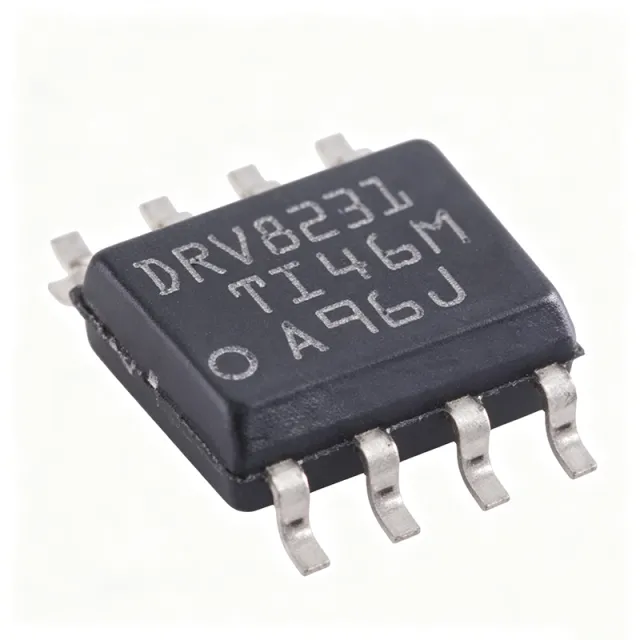
DRV8231 - 35V 3.7A H-Bridge Motor Driver | Texas Instruments
The Texas Instruments DRV8231 is a 35-V, 3.7-A brushed DC motor driver with integrated current regulation, supplied in a compact 8-pin WSON (DSG, 2x2 mm) package. It operates from a 4.5-V to 33-V supply rail and integrates four N-channel MOSFETs forming an H-bridge with a typical RDS(on) of 600 mOhm (including one high-side and one low-side FET). A brushed DC motor driver is a type of motor controller IC that switches power to a DC motor using an H-bridge of transistors, enabling forward, reverse, brake, and coast control. Within the power management IC hierarchy, motor drivers sit between logic-level microcontroller outputs and the power stage, and integrated H-bridge drivers like the DRV8231 combine gate drive, power FETs, charge pump, and protection in a single device. Key features include integrated current regulation with programmable current limit via the ILIM pin, a charge pump that supports 100% duty cycle operation and full N-channel H-bridge efficiency, and low-voltage logic inputs compatible with 3.3-V and 5-V controllers. Two logic inputs (PWM interface on the DRV8231D variant, PH/EN interface on the DRV8231A variant) control the bridge states, minimizing MCU pin usage and firmware complexity. Technically, the DRV8231 family offers pin-to-pin scalable RDS(on) and supply voltage options, allowing designers to support various loads and rails with minimal PCB changes. Integrated protection includes undervoltage lockout, overcurrent protection, and thermal shutdown, reducing external component count and board area compared to discrete MOSFET bridge solutions. Typical applications include brushed DC motor control in printers, small appliances, actuators, robotics, factory automation systems, and consumer electronics, where the compact 2x2 mm WSON-8 package fits space-constrained designs and integrated current regulation protects the motor and PCB traces without an external sense resistor network. When designing with the DRV8231, set the current limit using the ILIM pin resistor per the datasheet equation and provide a solid power ground plane under the exposed pad, since bridge conduction losses scale with the 600 mOhm typical RDS(on) at higher load currents.
DRV8242SQRHLRQ1 - 40V 6A Automotive H-Bridge Driver | Texas Instruments
The Texas Instruments DRV8242SQRHLRQ1 is an automotive-qualified 40V, 6A H-bridge motor driver with integrated high-side current sensing and feedback, housed in a 20-pin VQFN (RHL) package measuring 3.5 x 4.5 x 0.9 mm and rated for operation from -40C to +125C. An H-bridge motor driver is a power management IC that controls the direction, speed, and braking of a DC motor by switching four internal power transistors in complementary pairs. H-bridge drivers sit within the motor driver family of the broader power management IC hierarchy, bridging the gap between low-voltage logic controllers and the inductive loads of brushed DC motors, stepper motors, and actuators used across automotive and industrial systems. Key features include the integrated 40V-rated N-channel H-bridge, an integrated charge pump regulator for high-side gate drive, and on-chip current sensing with regulation that eliminates the need for external sense resistors. Control is provided through PWM or SPI interfaces, and a low-power sleep mode minimizes quiescent current for always-on automotive modules. The DRV8242-Q1 family shares an identical pin function across variants with scalable RON (on-resistance) to match different load currents, allowing designers to scale power capability without PCB redesign. Integrated protection circuitry covers overcurrent, thermal, and supply fault conditions, and the current-proportional output feeds motor current data back to the microcontroller for closed-loop control and diagnostics. Typical applications include automotive brushed DC motor modules such as pumps, fans, actuators, HVAC dampers, seat adjusters, and door latches, as well as industrial motion control where a compact 4.5V to 35V supply range and 6A continuous current are required. When designing with this device, exploit the integrated current-sense regulation to remove external shunt resistors, but ensure the VQFN exposed pad is soldered to an adequate PCB thermal plane to dissipate conduction losses at full 6A load. Verify that the supply path tolerates inductive kick-back beyond the 40V rating during aggressive PWM braking. This page synthesizes verified distributor pricing, drop-in same-family alternatives, and practical design notes not found in the manufacturer datasheet, giving engineers a complete sourcing and design reference for the DRV8242SQRHLRQ1.
DRV8243SQRHLRQ1 - 40V, 12A Automotive H-Bridge Driver | TI
The Texas Instruments DRV8243SQRHLRQ1 is an automotive-grade 40-V, 12-A H-bridge motor driver with integrated current sensing, integrated N-channel power FETs, and SPI-based configurable control, housed in a thermally enhanced VQFN-HR (RHL) power package and qualified to AEC-Q100 for automotive deployment. An H-bridge driver is a power management IC that controls the direction, speed, and braking of DC motors and other inductive loads by switching four bridge arms in controlled combinations. Within the power electronics hierarchy, the DRV8243-Q1 belongs to the integrated motor driver family: a monolithic device combining gate drive, power stage, current sensing, diagnostics, and protection in a single package, eliminating the need for discrete MOSFETs and gate drivers. Key features include a 40 V absolute maximum supply rating supporting 12-V automotive battery systems with load-dump headroom, up to 12 A of current capability from an integrated N-channel H-bridge on a BiCMOS high-power process, and high-side current sensing with regulation plus a current-proportional analog feedback output. The SPI (SQ) control interface allows configuration of off-state diagnostics, current regulation thresholds, slew-rate control, and detailed fault reporting, enabling predictive maintenance and functional-safety architectures. The DRV824x-Q1 family is fabricated on a monolithic BiCMOS high-power process that delivers excellent power handling and thermal performance. The family shares an identical pin function across members with scalable RON, so designers can trade current capability against cost without a PCB respin. A low-power sleep mode minimizes quiescent battery drain, and an integrated charge pump guarantees full enhancement of the high-side N-channel FETs across the supply range. Typical applications include automotive body and comfort functions such as power liftgates, power seats, window lifters, sunroof and pump actuators, as well as industrial 12-V brushed-DC motor drives requiring rich diagnostics. The integrated current-sense amplifier with proportional output removes the external sense resistor in many designs, saving board area and improving efficiency. Design consideration: because the bridge power FETs are integrated, thermal design centers on PCB copper area under the power pad; estimate conduction losses as I^2 x RON per arm and verify junction temperature against the AEC-Q100 Grade 1 ambient range. This page synthesizes distributor pricing, drop-in family alternatives, comparison tables, and practical design notes not found in the manufacturer datasheet.