센서
하위 카테고리
제품 (525)

TMP411 - ±1°C Remote & Local Temp Sensor | Texas Instruments
The Texas Instruments TMP411 is a dual-channel digital temperature sensor that combines a local die-temperature measurement channel with a remote temperature sensing channel in a single VSSOP-8, SOIC-8, or SOT23-8 package. It is two-wire and SMBus interface-compatible and is specified over a temperature range of -40°C to 125°C. The remote temperature sensor uses diode-connected transistors, typically low-cost NPN- or PNP-type transistors or diodes that are an integral part of microcontrollers, microprocessors, or FPGAs. Remote accuracy is ±1°C for multiple device manufacturers, with no calibration needed. A temperature sensor is a device that measures temperature and converts it into an electrical signal. The TMP411 is a digital temperature sensor, which means it outputs temperature readings in a digital format over a serial interface, making it easy to interface with microcontrollers and digital systems. It falls under the category of temperature sensors, which are part of the broader sensor family used in various electronic systems for monitoring and control. Key features of the TMP411 include N-factor and series resistance correction, which improve remote sensing accuracy by compensating for non-idealities in the remote diode. It also features programmable temperature limits and an SMBus-compatible interface. The device operates from a supply voltage of 2.7V to 5.5V and has a resolution of 11 bits for both local and remote channels. The TMP411 uses a delta-sigma ADC to convert the analog temperature signals to digital. It includes multiple registers for configuration and temperature data storage. The N-factor correction allows the device to be used with a wide variety of remote diodes, while series resistance correction compensates for resistance in the PCB traces, ensuring accurate readings even with long traces. Typical applications include system thermal management in computers, servers, and industrial equipment, as well as environmental monitoring and battery management. The TMP411 is ideal for applications where accurate remote temperature sensing is required, such as monitoring the temperature of CPUs, GPUs, or other hot components. When designing with the TMP411, ensure proper PCB layout to minimize noise on the remote sensing lines. Use a filter capacitor on the D+ and D- lines to reduce noise. Also, consider the supply voltage and ensure it is within the specified range for reliable operation.
TMP411-Q1 - ±1°C Remote/Local Temp Sensor | Texas Instruments
The Texas Instruments TMP411-Q1 is an automotive-grade dual-channel digital temperature sensor combining a local die-temperature channel and a remote junction-temperature channel in a single 8-pin VSSOP (DGK) package. It operates from a 2.7V to 5.5V supply over an ambient range of -40°C to +125°C, with remote measurement up to 150°C and ±1°C remote accuracy. A temperature sensor converts thermal energy into an electrical signal for monitoring and control. The TMP411-Q1 belongs to the digital temperature sensor class, outputting 12-bit readings over an I2C/SMBus two-wire interface instead of an analog voltage. Within the thermal-management hierarchy it sits as a remote/local digital sensor monitor within the broader sensor and power-management families used across automotive, industrial, and computing platforms. Key features include programmable non-ideality (N) factor and series-resistance cancellation, which compensate for external transistor non-idealities and PCB trace resistance to preserve accuracy across the full range. Programmable resolution and threshold limits, minimum/maximum temperature monitors, diode fault detection, and a temperature alert function complete the feature set. Technically, the TMP411-Q1 uses an internal ADC to measure the voltage across a diode-connected remote transistor, typically NPN/PNP devices embedded in MCUs, MPUs, or FPGAs. N-factor correction adjusts for the ideality factor of the external transistor, while series-resistance correction cancels line-resistance error. SMBus timeout and alert-response support improve bus robustness, and low shutdown quiescent current (approximately 8 uA) suits always-on automotive nodes. Typical applications include automotive battery management systems, engine control units, infotainment processors, and CPU/GPU thermal monitoring in embedded and data-center systems, where accurate remote junction sensing directly protects performance and reliability. Design tip: keep remote-sense traces short and routed as a differential pair away from noise, configure the N-factor and series-resistance registers to match the external transistor, and use pull-ups on the open-drain I2C and alert lines. Prices shown are as of 2026-08-29.

TMP411ADGKR - ±1°C Remote/Local Temp Sensor | TI | I2C/SMBus
The Texas Instruments TMP411ADGKR is a remote and local digital temperature sensor with ±1°C remote and local accuracy, an 11-bit digital output, and a wide -40°C to +125°C operating range, housed in an 8-pin VSSOP (DGK) surface-mount package with two-wire I2C/SMBus serial interface. A remote digital temperature sensor measures temperature by sensing the junction voltage of a diode-connected transistor that is often built into a microcontroller, microprocessor, or FPGA die. Because this sensing element sits directly on the hot silicon, remote sensors like the TMP411 report die temperature far more accurately than board-level thermistors or local-only sensors. The TMP411 belongs to the temperature sensor hierarchy: temperature sensor IC -> digital temperature sensor -> remote/local digital sensor -> thermal monitoring IC within a broader system-monitoring stack. Key features include programmable non-ideality (N) factor correction, which compensates for the manufacturing variation of the remote transistor, and series resistance cancellation that removes the error caused by PCB trace resistance between the sensor and remote diode. An ALERT output flags out-of-limit temperatures, while offset registers allow one-point system calibration for even tighter accuracy. The device is pin- and register-compatible with the Analog Devices ADT7461, giving designers a proven second source. The sensor digitizes both its own local die temperature and the remote diode temperature with 11-bit resolution (0.125°C steps in extended mode), and communicates over an industry-standard two-wire SMBus/I2C bus that supports multiple slave addresses selected by the ADD pin. Fault queueing and bus-timeout detection guard against bus lock-up in noisy environments. Typical applications include CPU, GPU, and FPGA die-temperature monitoring in servers and networking equipment, thermal supervision of power supplies and base stations, and industrial automation modules requiring two independent temperature zones from one IC. In layout, keep the DXP/DXN routing symmetric and short; the series-resistance cancellation handles a few ohms of trace resistance, but excessive capacitance or noise pickup on the differential pair degrades remote accuracy. This page adds value beyond the manufacturer datasheet by synthesizing distributor pricing as of 2026-09-02, drop-in alternatives (including the ADT7461 cross-brand equivalent), and practical PCB design notes into a single engineering reference.

TMP411ADR - ±1°C Remote/Local Temp Sensor | TI | SOIC-8
The Texas Instruments TMP411ADR is a ±1°C remote and local digital temperature sensor with N-factor and series-resistance correction, an 11-bit resolution output, and an I2C/SMBus serial interface, housed in an 8-pin SOIC (D) package. It measures its own die temperature (local channel) plus an external diode-connected transistor, typically integrated in a microcontroller, microprocessor, or FPGA die, over a -40°C to +125°C sensing range from a 2.7V to 5.5V supply. A remote/local temperature sensor is a monitoring IC within the broader power-management and thermal-management hierarchy of an electronic system. Unlike a standalone thermistor or analog-output sensor, it digitizes temperature internally and reports readings over a two-wire bus, allowing a host controller to poll multiple thermal zones, trigger alerts, and throttle clocks or fans before damage occurs. Remote-junction sensing is essential because the hottest point in modern electronics is usually the silicon die itself, not the PCB surface. Key features include ±1°C remote diode accuracy, programmable non-ideality (N-factor) correction that lets the device match different processor thermal diodes, and series-resistance cancellation that removes D+/D- PCB trace resistance error. An ALERT output flags out-of-limit readings while a THERM output provides a comparator-style hot-limit signal for direct fan or shutdown control. Architecturally, the TMP411 uses a delta-sigma ADC to convert the ratio of two diode forward currents into a digital temperature code with 0.0625°C LSB (11-bit), and applies digital correction factors for beta and series resistance. Typical applications include CPU/FPGA/GPU die temperature monitoring in servers and networking equipment, thermal supervision in industrial automation, and fan-speed control loops in power supplies and base stations. Design consideration: keep D+ and D- traces short, routed as a differential pair away from switching noise, since series resistance and coupled noise directly degrade remote accuracy. This page adds value beyond the datasheet by consolidating distributor pricing, drop-in alternatives, comparison tables, and practical design notes in one place.
TMP411AQDGKRQ1 - ±1°C Remote/Local Temp Sensor AEC-Q100 | TI
The Texas Instruments TMP411AQDGKRQ1 is an automotive-qualified (AEC-Q100) remote and local digital temperature sensor with N-factor and series-resistance correction, offering ±1°C remote accuracy across a -40°C to +125°C sensing range in an 8-pin VSSOP (DGK) package with a 2-wire SMBus interface and 11-bit output resolution. A remote temperature sensor is a power-management IC that measures die temperature of external devices such as CPUs, GPUs, FPGAs, and microcontrollers by sensing the base-emitter voltage of a diode-connected transistor integrated in those chips. Remote sensors sit within the broader hierarchy of temperature sensors, digital temperature sensor ICs, and thermal monitoring subsystems, and are a core element of system-level thermal management in electronics. Key features include ±1°C remote accuracy for multiple IC manufacturers' on-chip transistors, remote and local temperature channels, programmable N-factor correction, and series-resistance correction that cancels PCB trace resistance errors. The TMP411-Q1 supports programmable high- and low-temperature limits with ALERT and THERM outputs for fault and overtemperature indication, all monitored over a 2-wire SMBus serial interface. The device operates from a 2.7V to 5.5V supply and digitizes temperature with 11-bit resolution, giving 0.125°C steps. The N-factor correction register allows adaptation to different transistor ideality factors, while series resistance correction compensates up to a specified ohmic value on the D+/D- lines, eliminating the largest systematic remote-sensing error source without external calibration. Typical applications include automotive ECU and infotainment thermal monitoring, CPU/FPGA die-temperature supervision in industrial and telecom equipment, and overtemperature protection in power supplies and base stations. Design tip: minimize and match the D+/D- trace lengths and use the series-resistance correction register to cancel residual board resistance; place the local sensor away from high-dissipation components to keep local readings representative. This page adds distributor-sourced pricing, drop-in alternatives within the TMP411-Q1 family, and practical design notes that go beyond the manufacturer datasheet.
TMP411BDGKR - ±1°C Remote/Local Temp Sensor | Texas Instruments
The Texas Instruments TMP411BDGKR is a ±1°C remote and local temperature sensor with N-factor and series-resistance correction, featuring an 11-bit digital output and -40°C to +125°C operating range, housed in an 8-pin VSSOP (MSOP-8, DGK) package. A remote/local digital temperature sensor is a monitoring IC that measures temperature both at its own silicon (local channel) and at a remote diode-connected transistor (remote channel), typically a low-cost NPN or PNP device integrated into a microcontroller, CPU, GPU, or FPGA die. These sensors form part of the thermal management hierarchy — sensor, monitor, supervisor, power-management IC — and communicate measurements to a host controller over a serial bus such as I2C or SMBus so that fan speed, clock throttling, or system shutdown can be managed automatically. Key features include ±1°C maximum accuracy on both local and remote channels, 11-bit resolution (0.125°C per LSB) on the remote channel, support for a 2.7V to 5.5V supply range, and programmable N-factor correction that accommodates different transistor beta characteristics. The built-in series-resistance correction cancels the error introduced by PCB trace resistance in the remote diode loop, eliminating a common source of measurement error without precision layout constraints. Architecturally, the TMP411 uses a delta-sigma style remote diode measurement with automatic averaging, beta compensation, and programmable offset registers. Its ALERT/THERM output supports interrupt and thermostat-style behavior with programmable high/low limits, and the ADD pin provides three selectable SMBus addresses for multi-device bus sharing. Pin and register compatibility with Analog Devices ADT7461 and ADM1032 simplifies migration between vendors. Typical applications include CPU/FPGA/GPU die temperature monitoring in servers and networking equipment, thermal supervision in industrial controls and base stations, and power-supply over-temperature protection where the remote diode monitors a hotspot the local sensor cannot reach. Design consideration: place the TMP411 thermally close to the local hotspot and route the D+/D- differential pair tightly, though series-resistance correction relaxes trace-resistance limits substantially. This page synthesizes distributor pricing, pin-compatible drop-in alternatives, design notes, and an AEO-optimized FAQ not found on the manufacturer datasheet alone.
TMP411CDGKT - ±1°C Remote/Local Temp Sensor MSOP-8 | TI
The Texas Instruments TMP411CDGKT is a ±1°C remote and local digital temperature sensor with N-factor and series-resistance correction, offering 11-bit (0.0625°C) resolution, a -40°C to +125°C sensing range, and a 2.7 V to 5.5 V supply, housed in an 8-pin VSSOP/MSOP (DGK) package. A remote digital temperature sensor is a monitoring IC that measures the junction temperature of a distant diode-connected transistor - typically an on-chip sensing diode built into a CPU, GPU, FPGA, or ASIC - in addition to its own local die temperature. These sensors form the monitoring layer of the power-management hierarchy, feeding a host controller over a two-wire SMBus/I2C-style interface so that fans, clock throttling, and shutdown protection can react to real silicon temperatures. Key features of the TMP411C include ±1°C remote diode sensing accuracy, ±1°C local accuracy across the operating range, programmable non-ideality (N-factor) correction to compensate for different process transistors, and automatic series-resistance cancellation that removes the error caused by PCB trace resistance of up to several hundred ohms in the D+/D- loop. Architecturally, the device excites the remote diode with two different currents and measures the resulting delta-VBE, converting it through an on-chip 11-bit ADC into a two-wire digital code. Register-based high and low limits drive the ALERT and THERM outputs, allowing both interrupt-driven and hardware-throttle fault responses without host intervention. Typical applications include CPU/FPGA/ASIC junction monitoring in servers, telecom line cards, and industrial control systems, where the N-factor and series-resistance corrections let one PCB footprint support many silicon vendors. Design consideration: place the sensor close to the heat source and use a diode-connected NPN with a recommended operating range; route D+/D- as a closely coupled pair to minimize noise pickup. This page synthesizes distributor pricing, drop-in alternatives, pinout data, and practical design notes not found in the manufacturer datasheet.
TMP411CDR - ±1°C Remote/Local Temp Sensor | TI | SOIC-8
The Texas Instruments TMP411CDR is a ±1°C remote and local digital temperature sensor with N-factor and series-resistance correction, a 2.7 V to 5.5 V supply range, and an SMBus/I2C-compatible digital output, housed in an 8-pin SOIC (D) package. A remote and local temperature sensor is a class of digital temperature monitor IC within the broader hierarchy of temperature sensors -> thermal management ICs -> system monitoring. These devices measure the temperature of a remote diode-connected transistor - typically a low-cost NPN or PNP transistor integrated into a microcontroller, microprocessor, or FPGA die - while also measuring ambient temperature at the sensor's own die with an internal local channel. Key features of the TMP411 include ±1°C remote temperature accuracy and ±1°C local accuracy, a sensing range of -40°C to +125°C, 11-bit resolution, and two unique correction mechanisms: N-factor correction (which compensates for the beta/N-factor of the specific remote transistor) and series-resistance correction (which cancels PCB-trace resistance errors in the D+/D- remote loop). An SMBus ALERT/THERM output supports interrupt-driven thermal fault handling. Technically, the remote channel uses a two-current-ratio delta-VBE measurement technique; the series-resistance correction cancels up to approximately 100 ohms of parasitic resistance, enabling long or lossy PCB traces to the remote junction. The digital interface operates over SMBus with 2.7 V to 5.5 V logic compatibility, and the temperature data register is read as two bytes for the 11-bit result. Typical applications include CPU/GPU/FPGA die-temperature monitoring in servers and networking equipment, thermal supervision in industrial automation controllers, and power-supply or power-module temperature reporting where the remote diode sits on a hot component. Design consideration: place the 0.1 uF input decoupling capacitor close to the V+ pin, and route the D+/D- traces as a twisted or closely coupled pair away from high-dv/dt switching nodes to preserve the ±1°C accuracy specification. This page synthesizes verified distributor data, drop-in alternatives, and practical design notes not found in the manufacturer datasheet.

TMP411CQDGKRQ1 - ±1C Remote/Local Temp Sensor AEC-Q100 | TI
The Texas Instruments TMP411CQDGKRQ1 is an automotive-grade AEC-Q100 qualified remote and local digital temperature sensor with ±1°C remote accuracy, 11-bit resolution, and N-factor and series-resistance correction, housed in an 8-pin VSSOP (DGK) package operating from -40°C to +125°C. A remote/local temperature sensor is a digital IC in the temperature sensor family of semiconductor devices that monitors two thermal points simultaneously: an on-chip local sensor and a remote sensing transistor. The remote element is typically a diode-connected NPN or PNP transistor that is built into microcontrollers, microprocessors, FPGAs, or ASICs. These sensors digitize the remote junction temperature and communicate it over a 2-wire serial interface (I2C/SMBus), sitting at the top of the monitoring hierarchy in thermal management systems. Key features of the TMP411CQDGKRQ1 include remote accuracy of ±1°C for multiple IC manufacturers' on-chip transistors, 11-bit digital output resolution, N-factor correction that allows beta compensation for different process transistors, and series resistance correction that cancels the error caused by PCB trace resistance in the D+/D- loop. The device integrates alert and THERM outputs for over-temperature interrupt and throttling control, supporting both hardware and software thermal management schemes. The TMP411 architecture uses a band-gap-based local sensor and a delta-VBE remote measurement core. Successive-approximation conversion delivers the 11-bit result, while programmable registers set conversion rate, high/low temperature limits, and hysteresis. The 2-wire serial interface (I2C-compatible, SMBus) supports multiple devices on one bus, and the ALERT output supports SMBus protocol actions. Typical applications include FPGA and microprocessor die-temperature monitoring in networking and telecom equipment, automotive ECUs and infotainment thermal supervision, and server/datacenter board-level thermal management where remote diode sensing is required. Design tip: keep the D+ and D- traces matched and short; the series-resistance correction handles residual trace resistance, but noise pickup on long runs still degrades accuracy - filter and guard these lines. This page adds value beyond the manufacturer datasheet by compiling distributor pricing tiers, drop-in same-family alternatives, design notes, and an AEO-optimized FAQ for engineering and sourcing teams.
TMP411EDGKR - ±1°C Remote/Local Temp Sensor | Texas Instruments
The Texas Instruments TMP411EDGKR is a ±1°C remote and local digital temperature sensor with N-factor and series-resistance correction, a 12-bit output resolution, and an operating range of -55°C to +150°C, housed in an 8-pin VSSOP (DGK) package. A remote digital temperature sensor measures the junction temperature of an external diode-connected transistor - typically a low-cost NPN or PNP device that is already integrated inside a microcontroller, microprocessor, or FPGA. Together with its built-in local channel, the device forms a complete thermal-monitoring subsystem within the broader hierarchy of board-mount temperature sensors and system-management ICs, communicating results over an SMBus/I2C two-wire interface. Key features include ±1°C remote channel accuracy and ±1°C local channel accuracy for multiple device temperatures, a wide supply range of 2.7V to 5.5V, programmable N-factor correction that accommodates different transistor process characteristics, and series-resistance cancellation that removes the error introduced by PCB trace resistance in the D+/D- path. The 12-bit conversion result gives approximately 0.0625°C resolution on the remote channel. Architecture-wise, the TMP411 uses two modulated bias currents through the external sensing diode; the delta-VBE voltage is digitized by an internal ADC, and the N-factor correction register lets the device match the ideality factor of the specific processor die being monitored. The register map and pin arrangement are compatible with the Analog Devices ADT7461 and ADM1032, easing migration in existing server and networking thermal designs. Typical applications include CPU/FPGA/GPU junction-temperature monitoring in servers, base-station and networking switch thermal supervision, and industrial systems requiring both ambient (local) and hotspot (remote) sensing. For design, keep the D+/D- traces twisted and away from switching nodes; series-resistance correction tolerates up to a few ohms of trace resistance, but excessive capacitance on D+ slows or stops valid conversions. This page synthesizes distributor pricing, pin-compatible alternatives including the ADT7461 and ADM1032, and practical design notes not found in the manufacturer datasheet.

TMP421AQDCNTQ1 - ±1°C Remote/Local Temp Sensor, AEC-Q100 | TI
The Texas Instruments TMP421AQDCNTQ1 is an AEC-Q100 qualified ±1°C remote and local digital temperature sensor in an 8-pin SOT-23 package. It monitors a local on-die sensor plus one external diode-connected transistor (typically the substrate transistor of a microcontroller, CPU, or FPGA), reports results as 12-bit two's-complement codes, and supports a remote measurement range of -40°C to +150°C with a local range of -40°C to +127°C. Communication is via a two-wire SMBus/I2C-compatible serial interface with up to nine user-selectable addresses. The TMP421AQDCNTQ1 is the automotive-grade version of the TMP421, delivering ±1°C remote accuracy (versus ±2.5°C for the industrial TMP421AIDCNR), making it well suited to under-hood and cabin thermal management. A remote-junction digital temperature sensor is an integrated transducer that converts a diode-connected transistor's forward-voltage drop into a digital temperature code. Unlike analog thermistors, it applies series-resistance cancellation and a programmable non-ideality factor so that layout series resistance and discrete-transistor beta variation do not degrade accuracy. Within the broader system hierarchy this places the TMP421AQDCNTQ1 at the Sensors > Temperature Sensors layer, used alongside power management ICs, supervisors, and fan controllers. Key features include a 2.7V to 5.5V supply range, diode-fault detection for open/short conditions, configurable conversion rate, and a high-impedance analog input that ignores parallel paths. The SOT-23-8 footprint integrates into tight PCBs such as M.2 modules, server DIMMs, and battery-pack monitors where board area is constrained. Typical applications include automotive infotainment SoC thermal monitoring, server/SSD controller die-temperature reading, and battery-pack MOSFET thermistor replacement. When designing, place the TMP421AQDCNTQ1 within 10 cm of the remote diode and route the D+/D- traces as a matched differential pair to preserve ±1°C accuracy; this is the same layout rule TI recommends in the TMP42x-Q1 datasheet. When designing with this device, ensure the external NPN/PNP is the substrate-diode of the monitored device when possible, since that path has the lowest series resistance and the best matched ideality factor. The remote D+/D- traces should be routed symmetrically, not over a split plane, to avoid leakage-induced offset.

VCNL36821S - 940nm IR Proximity Sensor, I2C, 300mm | Vishay
The Vishay VCNL36821S is a fully integrated proximity sensor (PS) that combines an infrared emitter (IRED), photodiode, signal processing IC, and 12-bit ADC into a single compact 8-pin SMD package. It operates from 1.7 V to 3.6 V supply voltage, drives the internal IRED at up to 156 mA pulsed current, and detects reflected 940 nm infrared light up to 300 mm distance through an I2C bus. The CMOS monolithic integration provides excellent ambient light rejection and low power consumption suitable for battery-powered devices. A proximity sensor is a non-contact optoelectronic device that emits infrared light and measures the intensity of light reflected back from a nearby object to estimate distance. The VCNL36821S belongs to the broader category of optical/photoelectric sensors, which sit within the sensor hierarchy: proximity sensor -> optical sensor -> environmental sensor -> semiconductor IC. This category enables touchless user interfaces in handheld, wearable, and consumer electronics by replacing mechanical buttons and capacitive touch panels. Key features include 12-bit proximity resolution, programmable IRED current up to 156 mA for adjustable range, individual high/low interrupt thresholds for power-saving wake-up, and a fixed I2C address interface with standard (100 kHz) and fast (400 kHz) modes. The integrated 940 nm IRED is invisible to the human eye and immune to sunlight interference when paired with the on-die-band optical filter. The 8-pin SMD module package is reflow-solderable per JEDEC J-STD-020 and rated MSL 3. The architecture uses a CMOS process with on-chip photodiodes, transimpedance amplifiers, and a 12-bit successive-approximation ADC. Programmable IRED drive current allows designers to trade off range versus power consumption: lower current for short-range ear-detection in earbuds, higher current for longer-range presence detection in laptops. The interrupt engine runs autonomously in the background, allowing the host MCU to sleep until an object crosses the threshold. Typical applications include smartphone and tablet touchless gesture control, true wireless stereo (TWS) earbud in-ear detection, laptop/lid-close detection, smart speaker user-presence wake-up, and industrial proximity sensing. The compact 8-SMD footprint fits inside space-constrained enclosures where discrete photodiodes plus analog front-end ICs would not fit. When designing with this device, keep the IRED drive current within the 156 mA pulsed maximum and place a 1 uF decoupling capacitor within 3 mm of the VDD pin to suppress switching transients. Use the interrupt pin rather than polling to maximize battery life. This page synthesizes Vishay datasheet parameters, distributor pricing tiers, drop-in alternatives, and practical application notes not found in the standalone manufacturer datasheet, giving engineers a single-page reference for design and sourcing decisions.

VCNL36821S-SB - VCNL36821S Proximity/ALS SensorXplorer™ Board | Vishay
The Vishay VCNL36821S-SB is a SensorXplorer™ demonstration board designed to evaluate the capabilities of the VCNL36821S proximity sensor and ambient light sensor (ALS) in a plug-and-play hardware platform. The board integrates the VCNL36821S sensor module and provides a 1.7 V to 3.6 V operating voltage range with 940 nm IR LED emitter and 156 mA peak drive capability, intended for handheld device and consumer product prototyping. What is a SensorXplorer™ demonstration board? A sensor evaluation board is a reference design platform provided by a sensor manufacturer to let engineers quickly characterize optical, motion, or environmental sensors without designing custom PCB hardware. The SensorXplorer™ family from Vishay is a USB-driven ecosystem where the daughter sensor board (such as VCNL36821S-SB) plugs onto a main controller board to provide I2C connectivity, power, and on-screen plotting of proximity counts and lux readings. Key features of the VCNL36821S-SB include a small SOT-23 footprint through the daughter-card VCNL36821S sensor module, integrated photodiodes, transimpedance amplifiers, and analog-to-digital converters realized on a single CMOS die. The proximity channel supports up to 300 mm detection range with programmable IRED current and individual high/low interrupt thresholds, while the ambient light channel delivers linear output over a wide dynamic range. I2C interface (up to 1 MHz) and a dedicated interrupt pin simplify integration with low-power microcontrollers. The board reflects the underlying VCNL36821S architecture, which combines a silicon photodiode, IRED, and digital signal processing in a single 8-pin SMD module. The CMOS process technology enables low standby current suitable for battery-powered always-on applications. Proximity programmable interrupt features of individual high and low thresholds offer the best utilization of resource and power saving on the microcontroller. Typical applications for the VCNL36821S-SB include smartphone proximity sensing for touch-screen lock, laptop/lid-close detection, smart speaker wake-on-approach, wearable tap/wear detection, and IoT presence detection in smart home hubs. Automotive cabin gesture detection is also feasible when paired with a qualified host MCU. When designing with this board, ensure the host controller can supply 1.7 V to 3.6 V to the sensor VDD and provides an I2C bus with proper pull-ups. The interrupt pin (pin 2 on the sensor) must be connected to a dedicated GPIO with the required pull-up resistor. This page synthesizes distributor stock levels, SensorXplorer™ ecosystem alternatives, and practical evaluation guidance not found in the standalone datasheet.

VCNL4040M3OE-H3 - 200mm I2C Proximity/ALS Sensor | Vishay Semiconductor
The Vishay Semiconductor VCNL4040M3OE-H3 is a fully integrated proximity sensor (PS), ambient light sensor (ALS), and high-power infrared emitter (IRED) housed in a single 8-pin SMD module with 200 mm (7.874 in) detection range, 16-bit I2C digital output, and 2.5 V to 3.6 V supply operation. It also operates as 3.3 V typical supply and includes an interrupt (INT) pin for threshold-based event signaling without continuous host polling. According to the Vishay datasheet for the VCNL4040 family, the device combines photodiodes, amplifiers, and analog-to-digital conversion circuits in a single CMOS die, allowing designers to replace a discrete photodiode-plus-ADC chain with one surface-mount module. Operating between 2.5 V and 3.6 V, the VCNL4040M3OE-H3 interfaces to any microcontroller over the standard I2C bus (up to 400 kHz fast mode) using a 7-bit slave address. A proximity sensor is an electronic module that emits infrared light and measures the intensity of the return signal to estimate the distance to a nearby surface. The SHIM (smart-LED-like) integration found in the VCNL4040 places the IRED driver, photo detection, ADC, and digital signal conditioning inside one package, and ambient light sensors share the same optical window to convert lux measurements into 16-bit digital counts via the same I2C bus. This category hierarchy maps to: proximity/ALS module -> optical sensor -> sensor IC -> semiconductor. The VCNL4040 occupies the position of a mid-range, fully integrated multi-function optical sensor in Vishay's VCNL product family, sitting between simpler PS-only modules and more expensive ToF (time-of-flight) alternatives. Key features include 16-bit effective resolution for both the ALS and PS channels, programmable IRED drive current with up to 200 mA peak pulse, integrated 940 nm IRED with factory-calibrated spectrum matching, and selectable integration times that allow designers to trade measurement noise against power consumption. The device integrates a low-noise photodiode, transimpedance amplifier, 16-bit sigma-delta ADC per channel, IRED driver with programmable current, I2C slave interface, and an interrupt output. A built-in temperature compensation mechanism mitigates IRED output drift across -40 °C to +85 °C. Eight selectable IRED modulation frequencies allow multi-device co-existence on the same PCB without cross- interference. Typical applications include display backlight dimming in smartphones and tablets, proximity detection for ear-detection in wearables, paper/hand presence detection in printers and copiers, automatic faucet and soap dispenser actuation, and industrial human-machine interface (HMI) touchless controls. Its compact 4.0 mm x 2.36 mm x 1.05 mm SMD footprint makes it well suited for space-constrained designs. When designing with this device, place a 100 nF bypass capacitor close to VDD and a 4.7 µF reservoir capacitor to handle IRED pulse transients. Keep the optical window free of opaque overmold and protect the front face with a transmissive IR cover that does not attenuate the 940 nm wavelength. Always honor the maximum IRED on-time duty cycle of 1% to avoid thermal damage. This page synthesizes distributor pricing, drop-in alternatives, and practical design notes not found in the manufacturer datasheet.

VEMD4210FX02 - AEC-Q102 530nm Ambient Light Photodiode | Vishay
The Vishay VEMD4210FX02 is an AEC-Q102 qualified high-speed, high-sensitivity PIN photodiode ambient light sensor in a compact surface-mount 0805 (2012 metric) package with a photosensitive area of 0.42 mm2. Its spectral sensitivity is matched to the human eye with a peak wavelength of 530 nm and no infrared bump, delivering a typical reverse light current of 0.014 uA under standard illumination conditions. A PIN photodiode is a semiconductor light detector whose intrinsic (I) layer between the P and N regions widens the depletion region, producing high quantum efficiency and fast response. Within the sensor hierarchy it belongs to photodiodes -> optical sensors -> ambient light sensors -> photodetectors, converting incident light into a photocurrent that downstream electronics amplify and digitize for backlight control or automatic light control (ALC). Key features include human-eye-matched 530 nm spectral response that rejects invisible IR contributions, AEC-Q102 automotive qualification for harsh optoelectronic environments, an operating temperature range of -40 C to +110 C, and a miniature 0805 footprint that supports standard SMT assembly on compact PCBs. Because it is a raw photodiode rather than an integrated IC, the VEMD4210FX02 offers design freedom: the transimpedance gain, filtering, and ADC scaling are chosen by the engineer, enabling custom dynamic ranges for dashboard backlight dimming, display ALC, and headlamp-independent light detection in vehicles. Typical applications include automotive LCD dashboard backlight dimming, automatic interior/headlamp light control, and light-based presence or dimming functions in industrial and consumer displays. Design consideration: because the spectral response already matches the human eye, an additional IR-cut filter is usually unnecessary, but the transimpedance amplifier feedback network must be shielded from leakage currents to preserve microamp-level photocurrent accuracy. This page synthesizes distributor listings, cross-reference research, and design guidance not found in the manufacturer datasheet; the VEMD5525FX02 top-view QFN sibling is also compared.
VL53L0CXV0DH/1 - Time-of-Flight Ranging Sensor | STMicroelectronics
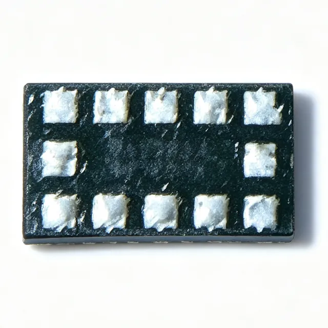
The VL53L0CXV0DH/1 is a Time-of-Flight (ToF) laser-ranging sensor module from STMicroelectronics, designed for accurate distance measurement up to 2 meters. It integrates a 940nm VCSEL (Vertical-Cavity Surface-Emitting Laser), a single-photon avalanche diode (SPAD) array, and a microcontroller in a compact optical module. The device communicates via I2C interface and operates from a 2.8V supply, making it ideal for battery-powered applications. A Time-of-Flight sensor measures distance by emitting a light pulse and measuring the time it takes for the reflected light to return. The VL53L0C uses a VCSEL to emit infrared light and a SPAD array to detect the reflection, calculating distance with millimeter-level accuracy. This technology is superior to infrared proximity sensors because it provides absolute distance measurement rather than just presence detection, and it is less affected by ambient light and target color. Key features include a measurement range of 30mm to 2000mm, an accuracy of ±3% at typical conditions, and a fast measurement time of less than 30ms. The module operates from a 2.8V supply with a typical power consumption of 20mW during active ranging. It includes an I2C interface with a configurable address, an interrupt output for ranging completion, and a built-in VCSEL driver. The device is housed in a 4.4mm x 2.4mm x 1.0mm optical module with an integrated lens, providing a field of view of 25 degrees. The VL53L0C uses STMicroelectronics' FlightSense technology, which combines a VCSEL, SPAD array, and advanced algorithms to achieve high accuracy and robustness. The module includes an on-chip microcontroller that handles ranging calculations, calibration, and ambient light rejection. The I2C interface supports standard and fast modes up to 400kHz, and the device can be programmed for different ranging modes, including single-shot and continuous. Typical applications include smartphone proximity detection, robotics obstacle avoidance, drone landing assistance, and consumer electronics such as automatic faucets and vacuum cleaners. The compact size and low power consumption make it suitable for portable and battery-operated devices. When designing with the VL53L0C, ensure a clean power supply with adequate decoupling, and place the module with a clear field of view. The device requires a cover glass with high infrared transmittance, and the I2C lines should be pulled up with appropriate resistors. Calibration is performed at the factory, but additional calibration may be needed for specific cover glass or system integration.
VL53L1CBV0FY/1 - Long Range Time-of-Flight Sensor | STMicroelectronics
The VL53L1CBV0FY/1 is a state-of-the-art Time-of-Flight (ToF) ranging sensor with enhanced performance, manufactured by STMicroelectronics. It integrates a complete ToF system in a compact optical module, enabling accurate distance measurement up to 4 meters. The sensor operates at a supply voltage of 2.8V and communicates via I2C interface, making it ideal for a wide range of proximity and ranging applications. A Time-of-Flight (ToF) sensor measures distance by emitting a light signal and calculating the time it takes for the light to reflect back from an object. This technology is distinct from infrared (IR) proximity sensors, which only detect presence, and from ultrasonic sensors, which use sound waves. ToF sensors are part of the broader category of optical sensors and are widely used in robotics, consumer electronics, and industrial automation for precise distance measurement. Key features of the VL53L1CBV0FY/1 include a long ranging distance of up to 4 meters, a fast ranging frequency of up to 50 Hz, and a field of view (FOV) of 27 degrees. The sensor is housed in an optical module package, which integrates the emitter, receiver, and optics in a single component. It operates over a temperature range of -30°C to +85°C, ensuring reliable performance in various environments. The VL53L1CBV0FY/1 uses STMicroelectronics' patented ToF technology, which employs single-photon avalanche diodes (SPADs) to detect reflected light. This architecture enables high accuracy and immunity to ambient light, making it suitable for outdoor applications. The sensor also features a programmable region of interest (ROI), allowing users to optimize the field of view for specific applications. Typical applications include smartphone proximity detection, robotics obstacle avoidance, drone landing assistance, and industrial safety systems. The sensor's long range and fast ranging frequency make it ideal for applications requiring real-time distance measurement, such as autonomous navigation and collision avoidance. When designing with the VL53L1CBV0FY/1, it is important to consider the optical interface. The sensor requires a clear line of sight to the target, and the cover glass or window must be transparent to infrared light. Additionally, proper power supply decoupling and PCB layout are critical to minimize noise and ensure accurate measurements.
VL53L3CXV0DH/1 - Time-of-Flight Ranging Sensor | STMicroelectronics
The VL53L3CXV0DH/1 is a Time-of-Flight (ToF) ranging sensor from STMicroelectronics, designed for high-accuracy distance measurement in a compact optical module. It integrates a single-photon avalanche diode (SPAD) array, a VCSEL light source, and a low-power microcontroller in a 4.4 x 2.4 x 1.0 mm optical LGA package. The sensor provides absolute distance measurement up to 300 cm with millimeter-level accuracy, making it suitable for a wide range of proximity, gesture, and ranging applications. A Time-of-Flight (ToF) sensor measures distance by emitting a light pulse and calculating the time it takes for the reflected light to return. The VL53L3CXV0DH/1 uses a VCSEL (Vertical-Cavity Surface-Emitting Laser) to emit infrared light and a SPAD array to detect the reflected photons. This technology enables fast, accurate, and reliable distance measurement even in challenging lighting conditions. ToF sensors are part of the broader category of optical sensors, which also includes ambient light sensors, proximity sensors, and image sensors. In a system hierarchy, the VL53L3CXV0DH/1 sits at the sensor layer, providing raw distance data to a host processor via an I2C interface. Key features of the VL53L3CXV0DH/1 include a ranging distance of up to 300 cm, a fast ranging frequency of up to 50 Hz, and a field of view (FOV) of 27 degrees. The sensor operates from a 2.8V supply voltage and communicates via I2C, with an interrupt output for event-driven operation. It also features an on-chip histogram processing algorithm that improves robustness against ambient light and multi-object detection. The device is RoHS compliant and operates over a temperature range of -30°C to +85°C. The VL53L3CXV0DH/1 uses a histogram-based ranging architecture that enables multi-object detection and improved accuracy in cluttered environments. The integrated VCSEL emits at 940 nm, which is invisible to the human eye and safe for consumer applications. The sensor's low power consumption (typically 20 mA during ranging) and small form factor make it ideal for battery-powered devices. The I2C interface supports standard and fast modes, allowing easy integration with microcontrollers. Typical applications include smartphone camera autofocus, robotics obstacle avoidance, drone landing assistance, smart home presence detection, and industrial safety systems. The sensor's ability to measure absolute distance, rather than just proximity, enables advanced features such as gesture recognition and 3D mapping. In robotics, the VL53L3CXV0DH/1 can be used for collision avoidance and navigation, providing accurate distance data to the control system. When designing with the VL53L3CXV0DH/1, ensure proper optical alignment and a clear line of sight to the target. The sensor requires a small aperture in the enclosure to allow the VCSEL and SPAD to operate correctly. Additionally, the I2C address can be configured via a single pin, allowing multiple sensors to be used on the same bus. For optimal performance, place the sensor away from other infrared sources and avoid covering the optical window with materials that absorb infrared light.
VL53L5CXV0GC/1 - 8x8 Multi-Zone Time-of-Flight Sensor | STMicroelectronics
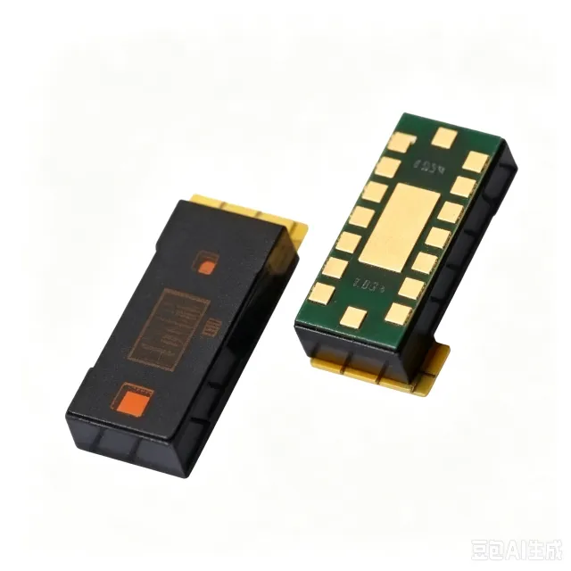
The STMicroelectronics VL53L5CXV0GC/1 is a state-of-the-art Time-of-Flight (ToF) ranging sensor with an 8x8 multi-zone capability, enabling simultaneous measurement of distances across 64 independent zones. It integrates a single-photon avalanche diode (SPAD) array, a low-power infrared laser, and advanced optics in a compact, reflowable module. The sensor operates at 940 nm wavelength, providing accurate ranging from 1 cm to 400 cm in typical conditions, with a field of view (FoV) of 61 degrees diagonal. It communicates via I2C (up to 1 MHz) or SPI interfaces, and includes an interrupt output for event-driven host communication. A Time-of-Flight (ToF) sensor is a type of optical sensor that measures distance by calculating the time it takes for emitted light to reflect off an object and return to the sensor. Unlike infrared proximity sensors that only detect presence, ToF sensors provide absolute distance measurements, making them essential for applications requiring precise depth sensing. In the broader system hierarchy, a ToF sensor is a type of optical sensor, which falls under the category of sensors, which are components of electronic systems that perceive the physical world. The VL53L5CXV0GC/1 is a direct ToF sensor, meaning it measures the round-trip time of light pulses directly, as opposed to indirect ToF methods that use phase-shift measurements. Key features of the VL53L5CXV0GC/1 include its 8x8 multi-zone ranging, which allows for depth mapping and object detection across a wide area. It offers a maximum ranging frequency of 60 Hz, enabling real-time depth sensing for gesture recognition and SLAM applications. The sensor has a low power consumption of 1.5 mA in continuous operation, making it suitable for battery-powered devices. It also features an on-chip microcontroller that handles ranging algorithms, reducing host processing load. The module is housed in a 6.4 mm x 3.0 mm x 1.5 mm optical module package, which is reflowable and compatible with standard SMT assembly. Technically, the VL53L5CXV0GC/1 uses a SPAD array to detect individual photons, achieving high sensitivity even in low-light conditions. The integrated laser driver emits short infrared pulses, and the time-of-flight is measured with picosecond resolution. The sensor includes a histogram-based algorithm that distinguishes multiple targets and suppresses crosstalk, improving accuracy in complex scenes. The device operates from a 2.8 V supply voltage, with I2C and SPI interfaces for flexible integration. It also includes a programmable GPIO for interrupt generation, which can be configured for various events such as new data ready or threshold crossing. Typical applications include robotics for obstacle avoidance and navigation, smart home devices for presence detection and gesture control, and consumer electronics for camera autofocus assistance. In robotics, the multi-zone capability allows the sensor to map the environment in real-time, enabling collision avoidance. In smart home devices, it can detect human presence for energy-saving automation. In camera systems, it provides fast and accurate autofocus even in low-light conditions. When designing with this sensor, ensure proper optical alignment and avoid covering the module with materials that are opaque to 940 nm light. The sensor requires a clean power supply with adequate decoupling, and the I2C address can be configured via a pin. For best performance, calibrate the sensor in the final product environment to account for cover glass and other optical elements.

W83960G - PC Hardware Monitor IC 64-LQFP | Winbond/Nuvoton
The Winbond W83960G (listed by Nuvoton Technology Corporation as W83960G REV. B) is a dedicated hardware monitoring IC designed for PC motherboard and embedded system health management, supplied in a 64-pin LQFP (low-profile quad flat package) surface-mount package. It integrates the core functions of a hardware monitor: multi-channel voltage sensing, temperature monitoring via thermistor and thermal-diode inputs, fan-speed (tachometer) measurement, and chassis-intrusion detection, communicating with the host over an ISA/LPC-style host interface typical of the W83xxx family. A hardware monitor IC (also called a hardware monitoring controller, H/W monitor, or environmental supervisor) is a mixed-signal power-management IC that sits low in the system hierarchy of supervisory devices: sensor -> hardware monitor -> embedded controller -> Super I/O -> power management subsystem. Its role is to continuously convert analog health signals - supply-rail voltages, processor and ambient temperatures, and fan rotation pulses - into digital register values that BIOS, SMM handlers, or OS-level utilities such as lm-sensors can read and act upon. Key functional blocks of the W83960G include an analog-to-digital conversion front end for voltage and temperature channels, fan tachometer counters with programmable limits, and limit-comparison logic that can assert interrupt or alarm outputs when measured values exceed programmed thresholds. According to distributor listings (DigiKey, Jotrin), the part is categorized under Thermal Management / Sensor Output and identified as an IC H/W MONITOR in 64-LQFP. Technically, devices of this class use on-chip ADCs with input multiplexers shared between voltage-divider-based rail monitoring (Vcore, Vcc, +3.3V, +5V, +12V, battery) and negative-temperature-coefficient thermistor inputs, plus a dedicated two-terminal thermal-diode input for CPU on-die temperature. Reading resolution and conversion rates are register-configurable, allowing trade-offs between polling latency and bus traffic. Typical applications include desktop and server motherboard monitoring, industrial PC and embedded x86 platforms, storage enclosures requiring fan-speed supervision, and test/burn-in stations that log environmental data. The 64-LQFP package suits high-pin-density motherboard designs. A key design consideration is board-level sensor wiring: thermistor and thermal-diode traces should be routed away from switching-regulator noise, and voltage sense dividers must match the datasheet ratio to preserve measurement accuracy. This page synthesizes distributor sourcing data, package information, and practical design guidance not found in any single distributor listing, providing engineers with a consolidated reference for the W83960G.
XMLP025BC11F - 25 bar Pressure Sensor, 0.5-4.5V, G1/4 | Schneider
The Schneider Electric XMLP025BC11F is a 25 bar electronic pressure transmitter from the OsiSense XM family, providing a 0.5 V to 4.5 V ratiometric analogue output over a G1/4 A male process connection conforming to DIN 3852-E. It operates from a 5 VDC SELV supply, draws 7 mA, and integrates a 3-wire EN 175301-803-A (ex DIN 43650) connector for plug-and-play hydraulic and pneumatic installations. The device uses a strain-gauge thin-film sensing cell with FPM (Viton) sealing for media compatibility from -30 °C to +135 °C. A pressure sensor is a transducer that converts an applied fluid pressure into a proportional electrical signal, and within the broader sensor taxonomy it belongs to the measurement-sensor family alongside temperature, flow, and level sensors. In an industrial control hierarchy, the XMLP pressure transmitter typically feeds an analogue input module of a PLC, a SCADA remote terminal unit, or a microcontroller-based data-acquisition front end, providing real-time hydraulic or pneumatic pressure data for closed-loop control and condition monitoring. Key differentiating features of the XMLP025BC11F include a wide 0 bar to 25 bar operating range with proof pressure of 75 bar and burst pressure of 150 bar, ±0.1 % repeatability per IEC 61298-2, ±1 % linearity (typical), and ratiometric 0.5-4.5 V output that cancels 5 V supply drift. The compact stainless-steel body with FPM seal supports air, fresh water, hydraulic oil, gas, and refrigeration fluids, eliminating the need for separate sensor SKUs per media type. The robust EN 175301-803-A connector supports field replacement without rewiring. At the silicon level the XMLP series relies on a piezoresistive Wheatstone bridge diffused into a stainless-steel diaphragm, laser-trimmed for offset and span, then conditioned by an Application-Specific Integrated Circuit (ASIC) providing ratiometric output, reverse-polarity protection, and short-circuit safeguards. The amplifier stage is calibrated so that 0.5 V corresponds to 0 bar and 4.5 V corresponds to 25 bar with a typical linearity of ±0.5 % of the full scale. The device is supplied with a traceability code per Schneider lot conventions and conforms to CE, UL, and CCC features. Typical applications include hydraulic-press pressure verification on machine tools, HVAC chilled-water and refrigerant line monitoring, compressed-air system pressure trending, injection-moulding clamp force feedback, and pump-discharge pressure supervision. In each case the 0.5-4.5 V ratiometric signal interfaces directly with industrial analogue inputs that expect a 0-5 V or 0-10 V proportional reading. When designing with the XMLP025BC11F, observe the 75 bar proof-pressure limit during transients such as water-hammer events, ensure the 5 V supply regulation stays within ±0.25 V to preserve ratiometric accuracy, and torque the G1/4 male fitting to 25-30 N·m using a thread sealant compatible with FPM/Viton. This part is now in end-of-commercialization status as of May 31, 2023, so design-in for new projects should target the active XMLP platform variants such as XMLP025BC71F. This page synthesizes distributor stock, end-of-life status from the Telemecanique Sensors product page, application guidance, and drop-in alternative constraints not found in the manufacturer datasheet alone.