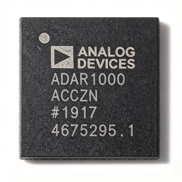
ADAR1000ACCZN - 8-16GHz 4-Ch X/Ku Beamformer | Analog Devices
부품 번호: ADAR1000ACCZN ✓ 활성| 수량 | 단가 | 합계 |
|---|---|---|
| 1 | $1848.4848 | $1,848.48 |
| 10 | $1794.697 | $17,946.97 |
| 50 | $1716.6667 | $85,833.34 |
| 100 | $1638.6364 | $163,863.64 |
ADAR1000ACCZN 개요
A beamformer IC is the core signal-routing element of an electronically steered antenna array. In a phased array system, each radiating element is driven by a beamformer channel that applies a calculated phase shift and gain weighting; by varying these weights across the array, the antenna beam is steered electronically without any mechanical movement. The ADAR1000 belongs to the RF transceiver and beam-steering hierarchy of microwave integrated circuits, sitting between the antenna elements and the transceiver or waveform generator.
Key features of the ADAR1000 include four independent receive and transmit channels covering the full 8 GHz to 16 GHz band, digitally controlled phase shifting in 360-degree range with fine LSB resolution, per-channel gain control for amplitude tapering, and bidirectional operation through a common RF_IO pin that connects directly to the antenna element. The half-duplex TDD architecture simplifies the front-end by eliminating separate transmit and receive signal paths to the radiator.
Technically, in receive mode input signals from four antenna elements pass through the four receive channels, where phase and amplitude are adjusted, and are combined at the common RF_IO port. In transmit mode, the RF_IO input signal is split and passes through the four transmit channels to the radiating elements. Control of all gain, phase, and T/R state is performed through a serial peripheral interface (SPI), enabling rapid beam reconfiguration under FPGA or microprocessor control.
Typical applications include X band and Ku band phased array radar for defense and aerospace platforms, satellite communications terminals, and electronic warfare systems requiring high-resolution beam steering.
When designing with the ADAR1000, pay close attention to supply sequencing, RF board layout for the chip-scale package, and thermal management, since beamformer ICs in dense arrays operate in thermally constrained enclosures.
This page synthesizes distributor availability, datasheet references, and practical design guidance not found on any single manufacturer or distributor page.
드롭인 대체품: ADAR1000ACCZN — 동일 패키지, 핀 호환. PCB 재작업이 필요한 다른 패키지 부품은 제외됩니다.
빠른 비교 도구 — 나란히 비교할 대체 부품을 선택하십시오:
이 제품에는 사용 가능한 드롭인 대체품이 없습니다.
대체품 요청ADAR1000ACCZN 사양
| Product Type | 4-Channel X/Ku Band Beamforming Core Chip |
| Frequency Range | 8 GHz to 16 GHz |
| Frequency Bands | X Band and Ku Band |
| Number of Channels | 4 |
| Operating Mode | Half-duplex (TDD), receive and transmit |
| RF Port Architecture | Common bidirectional RF_IO pin |
| Receive Path | 4 channels combined at RF_IO |
| Transmit Path | RF_IO split to 4 transmit channels |
| Control Interface | SPI (serial peripheral interface) |
| 패키지 | CC-88-1 (88-connection chip-scale package) |
| Typical Applications | Phased array radar, satellite communications |
| 실장 유형 | Surface Mount |
ADAR1000ACCZN cc-88-1 (88-connection chip-scale package) 핀 구성 가이드
ADAR1000ACCZN(cc-88-1 (88-connection chip-scale package) 패키지)의 핀 구성입니다. 핀 번호, 기능, 연결 다이어그램은 제조사 데이터시트에 정의되어 있습니다. 정확한 풋프린트와 솔더링 지침은 해당 문서를 참조하십시오.

다음에 대한 상세 핀아웃 데이터 없음: ADAR1000ACCZN.
다음을 참조하십시오: 데이터시트 전체 핀 구성은 다음을 참조하십시오.
일반적인 애플리케이션
ADAR1000ACCZN 적합 용도: 6 애플리케이션s: X Band Phased Array Radar, Ku Band Satellite Communications Terminals, Electronic Warfare (EW) Systems, Defense and Aerospace Phased Arrays, Test and Measurement Beamforming Setups, Maritime and Airborne SATCOM-on-the-Move.
X Band Phased Array Radar
The ADAR1000ACCZN is purpose-built for X band phased array radar tiles. Its 8 GHz to 16 GHz coverage fully encompasses X band radar allocations, and the four-channel architecture matches the common 4-element subarray tile used in both ground-based and airborne radar apertures. Per-element digital phase and gain control lets the array processor steer the beam and apply amplitude tapering for sidelobe suppression, which directly improves detection performance in clutter. The half-duplex TDD operation through the common RF_IO pin aligns naturally with pulsed radar waveforms, where transmit and receive are time-separated. Because phase and gain are set via SPI, beam dwell times can be changed on a pulse-to-pulse basis for multifunction radar modes.
추천
Ku Band Satellite Communications Terminals
For Ku band SATCOM flat-panel terminals, the ADAR1000ACCZN provides electronic beam steering within its 8 GHz to 16 GHz span, enabling the terminal to track geostationary satellites or operate on the move without gimbals. The four channels per device scale cleanly: an N-element panel uses N/4 devices, all controllable from a shared SPI bus with per-device addressing. The compact CC-88-1 chip-scale package fits the sub-wavelength element spacing demanded at Ku frequencies, and integrated gain control supports amplitude weighting to shape the transmitted pattern and meet regulatory sidelobe masks. The half-duplex architecture also matches the TDD structure used by many modern satcom waveforms.
추천
Electronic Warfare (EW) Systems
In electronic warfare applications such as direction finding and responsive jamming, the ADAR1000ACCZN supplies the fast, digitally controlled beam steering needed to place nulls and probe beams across the 8 GHz to 16 GHz threat band. Because the phase and gain of every channel are register-programmable, the EW processor can reconfigure the array response in microseconds to adapt to changing emitters. The combined four-channel receive output improves sensitivity against low-power threats, while the transmit path supports directional jamming energy placement. The monolithic integration of switching, phase shifting, and attenuation per channel eliminates the calibration drift associated with discrete function chains in high-vibration EW platforms.
추천
Defense and Aerospace Phased Arrays
Defense and aerospace radar programs favor the ADAR1000ACCZN because it integrates the complete per-element control function - T/R switching, phase shifting, and gain tapering - into one qualified RFIC, reducing component count on thermally and spatially constrained array tiles. The 4-channel granularity suits subarray architectures used in airborne fighter radar, naval surveillance radar, and missile seeker apertures. Digital control through SPI integrates cleanly with the FPGA-based beamforming controllers typical of these platforms, and the device's 8 GHz to 16 GHz band coverage allows a single beamformer design to be reused across X band and Ku band variants of the same system, amortizing development cost.
추천
Test and Measurement Beamforming Setups
Array test benches and beamforming proof-of-concept rigs use the ADAR1000ACCZN to emulate and validate steering algorithms at X and Ku bands. Its SPI register interface allows automated test equipment to sweep phase and gain states and measure pattern reproducibility, calibration accuracy, and temperature drift of the complete array chain. Because the four channels are monolithically matched, the device also serves as a controlled reference for characterizing element-to-element mutual coupling effects in compact apertures. Engineering teams evaluating SATCOM or radar prototypes can build a 4-element demonstration tile around a single ADAR1000 plus a companion transceiver before committing to full-scale array production.
추천
Maritime and Airborne SATCOM-on-the-Move
Maritime VSAT terminals and airborne connectivity apertures require antennas that maintain pointing accuracy while the platform pitches, rolls, and yaws. The ADAR1000ACCZN provides the electronic steering element for such flat-panel solutions across X and Ku bands. Its fine per-channel phase resolution lets the beam controller compensate platform attitude dynamically at update rates set by the SPI bus rather than by mechanical servo bandwidth, and the integrated gain tapering helps the terminal meet ITU sidelobe emission masks while maximizing EIRP. The surface-mount CC-88-1 package supports automated assembly of the dense element grids these low-profile apertures demand.
추천
추천 제품 요약
엔지니어링 참조 데이터: ADAR1000ACCZN — 비교, 설계 지침 및 규정 준수 정보.
선택 가이드
대체품과의 비교
| 파라미터 | 이 제품 |
|---|---|
| Package | CC-88-1 |
| Brand | Analog Devices |
| Frequency Range | 8 GHz to 16 GHz |
| Channels | 4 |
| Operating Mode | Half-duplex TDD |
| Phase/Gain Control | Digital, per-channel, via SPI |
| RF Port Architecture | Common bidirectional RF_IO |
| Drop-in Alternatives Available | None identified in verified web data |
주요 차별점
- Single-chip 4-channel integration for X and Ku bands (vs Discrete phase shifter + attenuator + SPDT switch chain)
- Common bidirectional RF_IO port (vs Separate TX/RX feed architectures)
- Dual-band coverage in one device (vs Band-specific beamformer designs)
설계 노트
The ADAR1000ACCZN uses the CC-88-1 chip-scale package, which requires careful land-pattern design and controlled-impedance RF routing to each of the four channel ports and the common RF_IO. Keep RF traces at 50 ohms matched to the datasheet-recommended stackup, place the device on the component side with a continuous ground plane directly beneath, and follow the Analog Devices ADAR1000 evaluation board (ADAR1000-EVALZ) layout as a reference for via stitching and decoupling placement. Coplanar waveguide with ground vias is recommended for the RF transitions.
Beamformer ICs of this class use multiple supply domains (RF, digital, and interface) that should each be locally decoupled with low-ESR ceramic capacitors placed at the package pins. Follow the supply sequencing and ramp-rate requirements given in the Analog Devices ADAR1000 datasheet to avoid latch-up during power-up, and verify the maximum supply tolerance before connecting to a shared array-tile power rail. Exact supply voltage values should be taken from the datasheet, as they were not captured in the data verified for this page.
The ADAR1000 is a half-duplex device - simultaneous transmit and receive operation is not supported. System firmware must enforce TDD timing through the SPI mode control and guarantee that the device has fully switched modes before applying RF energy on RF_IO. A second common pitfall is omitting per-device SPI addressing in multi-device array tiles; plan the SPI bus topology and device-enable mapping early, since retrofitting isolation on a dense tile is difficult.
규정 준수 정보
Compliance status for ADAR1000ACCZN was not explicitly stated in the verified web data. Obtain RoHS/REACH declarations from the Analog Devices product page or XAIPART.