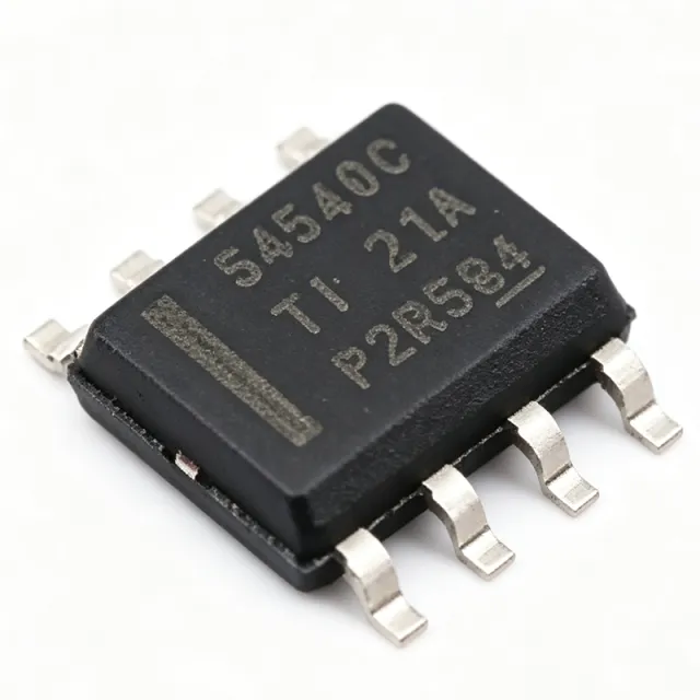
BQ24133QRGYRQ1 - 2.5A 1-3 Cell Buck Charger Q1 | TI
부품 번호: BQ24133QRGYR ✓ 활성| 수량 | 단가 | 합계 |
|---|---|---|
| 1 | $3.95 | $3.95 |
| 10 | $3.55 | $35.50 |
| 100 | $3.16 | $316.00 |
| 500 | $2.84 | $1,420.00 |
| 1,000 | $2.53 | $2,530.00 |
BQ24133QRGYR 개요
A switched-mode battery charger is a DC-DC converter-based power management IC that regulates charge current and battery voltage with far higher efficiency than linear chargers. Within the power-management IC hierarchy, the BQ24133 family sits between a generic buck regulator and a full battery management IC, adding charge termination, thermal regulation, and adapter-to-battery power path selection.
Key features include a 1.6-MHz constant-frequency synchronous PWM controller delivering up to 92% efficiency, a 30-V input rating with adjustable input overvoltage protection, a 4.5-V to 17-V operating input range, and an automatic power path selector between the adapter and battery. High-accuracy regulation of input current, charge current, and charge voltage enables the device to safely work with limited-adapter-power systems, while dynamic power management protects overloaded sources.
The device closely monitors battery pack temperature (TS pin with NTC) and permits charging only within a preset temperature window, an essential safety behavior for automotive and industrial lithium batteries. Integrated MOSFETs eliminate external discrete transistors, shrinking the solution footprint and reducing BOM count.
Typical applications include automotive infotainment and telematics backup batteries, industrial handheld instruments, portable medical devices, and battery-backed servers or gateways requiring seamless adapter-to-battery transition. The power path feature keeps the system alive even with a deeply discharged battery.
Design consideration: the 1.6-MHz switching frequency permits small inductors, but PCB layout of the power loop must be tight; place the inductor, input capacitor, and PGND connections per the datasheet layout guidelines to minimize EMI.
드롭인 대체품: BQ24133QRGYR — 동일 패키지, 핀 호환. PCB 재작업이 필요한 다른 패키지 부품은 제외됩니다.
이 시리즈의 변형
다음과 드롭인 호환되는 동일 시리즈 모델: BQ24133QRGYR (동일 폼 팩터 및 풋프린트) — 차이점: Battery Temperature Monitoring, Cell Count.
빠른 비교 도구 — 나란히 비교할 대체 부품을 선택하십시오:
BQ24133RGYR
✓ 재고 있음
$1.69 / 개
데이터시트 보기 →BQ24133RGYT
📋 참조 대체품 (카탈로그에 없음)
BQ24133QRGYTQ1
📋 참조 대체품 (카탈로그에 없음)
BQ24133RGER
📋 참조 대체품 (카탈로그에 없음)
BQ24179RGYR
📋 참조 대체품 (카탈로그에 없음)
BQ24133QRGYR 사양
| Battery Chemistry | Li-Ion / Li-Polymer |
| Cell Count | 1, 2, or 3 cells (4.2 V/cell) |
| Maximum Charge Current | 2.5 A |
| 토폴로지 | Synchronous buck (switched-mode) |
| 스위칭 주파수 | 1.6 MHz |
| Peak Efficiency | Up to 92% |
| Input Operating Voltage | 4.5 V to 17 V |
| Input Absolute Maximum Rating | 30 V with adjustable overvoltage protection |
| Integrated MOSFETs | Two N-channel power MOSFETs |
| Power Path | Automatic adapter/battery selector with dynamic power management |
| Battery Temperature Monitoring | TS pin NTC window monitoring |
| Control Type | Stand-alone (no host processor required) |
| 패키지 | VQFN-24 (RGY) 5.5 x 3.5 mm |
| 실장 유형 | Surface Mount |
| Automotive Qualification | AEC-Q100 qualified (Q1) |
| RoHS 상태 | Compliant |
BQ24133QRGYR 핀 구성
| 핀 1 | ACN — Input current sense negative |
| 핀 2 | ACP — Input current sense positive / adapter power |
| 핀 3 | VAC — Adapter voltage detect input |
| 핀 4 | OVPSET — Input overvoltage protection threshold set |
| 핀 5 | BTST — High-side gate driver bootstrap |
| 핀 6 | SW — Switching node (inductor connection) |
| 핀 7 | PGND — Power ground |
| 핀 8 | CSN — Charge current sense negative |
| 핀 9 | CSP — Charge current sense positive / battery sense |
| 핀 10 | TS — Battery temperature NTC monitor |
| 핀 11 | VREF — Reference output |
| 핀 12 | TERM — Termination threshold program |
| 핀 13 | ISET2 — Input current limit program |
| 핀 14 | ISET1 — Charge current program |
| 핀 15 | CELL — Cell count selection (1/2/3) |
| 핀 16 | CE — Chip enable |
| 핀 17 | PGATE — Power path selector gate drive |
| 핀 18 | AGND — Analog ground |
| 핀 19 | STAT — Charge status output |
| 핀 20 | PGOOD — Power good indicator |
| 핀 21 | REGN — LDO bias supply output |
| 핀 22 | DPM — Dynamic power management sense |
| 핀 23 | SYS — System power path output sense |
| 핀 24 | BOTFET — Battery disconnect FET drive |
일반적인 애플리케이션
BQ24133QRGYR 적합 용도: 6 애플리케이션s: Automotive Telematics and Infotainment Backup, Industrial Handheld Instruments, Portable Medical Devices, Battery-Backed Servers and Gateways, POS Terminals and Rugged Handhelds, IoT and Smart-Home Backup Power.
Automotive Telematics and Infotainment Backup
The BQ24133QRGYRQ1 is AEC-Q100 qualified and tolerates a 30-V input with adjustable overvoltage protection, matching load-dump-protected automotive 12-V rails. Its 1.6-MHz synchronous buck charges 1-3 cell Li-Ion backup batteries at up to 2.5 A with 92% peak efficiency, minimizing heat in sealed modules. The automatic power path keeps telematics units alive during crank or adapter dropout by seamlessly switching between adapter and battery, while NTC-based temperature window monitoring enforces safe pack charging.
추천
Industrial Handheld Instruments
Battery-powered field instruments benefit from the stand-alone operation of the BQ24133: resistor-programmed charging with no host MCU reduces firmware complexity. The 4.5-V to 17-V input accepts universal wall adapters, and 2.5-A charging refills 2-cell or 3-cell packs quickly. Up to 92% efficiency and 1.6-MHz switching allow a small inductor, keeping handheld enclosures compact. Power path selection lets the tool run directly from the adapter even with a fully discharged battery.
추천
Portable Medical Devices
Portable diagnostic and monitoring devices require quiet, efficient, and safe battery charging. The BQ24133's high-accuracy regulation of charge current and voltage protects sensitive Li-Polymer packs, while the TS-pin NTC window prevents charging outside safe temperatures - a patient-safety concern. The synchronous 1.6-MHz buck avoids low-frequency ripple near signal bands, and power path management guarantees uninterrupted operation during battery exchange, critical for mobile medical instrumentation.
추천
Battery-Backed Servers and Gateways
Network gateways and server BMC subsystems use the BQ24133 to maintain UPS-style battery backup. The 17-V operating input supports common 12-V intermediate buses, and dynamic power management limits adapter current draw when the source is overloaded. Charging a 3-cell (12.6-V) battery at up to 2.5 A provides meaningful ride-through time, and automatic adapter-to-battery transition occurs without host intervention, ensuring network hardware stays online through power interruptions.
추천
POS Terminals and Rugged Handhelds
Payment terminals and rugged scanners demand fast recharge times between shifts. The BQ24133 charges 1-2 cell packs at up to 2.5 A - a typical 2000-mAh cell refills in roughly one hour. Adjustable input OVP (30-V rating) protects against miswired adapters, a real field hazard. The stand-alone architecture with thermal regulation and NTC battery monitoring delivers certified-safety charging behavior without adding a supervisory MCU, simplifying product certification.
추천
IoT and Smart-Home Backup Power
Smart hubs, door controllers, and security panels require seamless failover to battery during outages. The BQ24133's automatic power path selector maintains the system rail from the adapter while trickle-refilling the backup cell; on adapter loss, the battery takes over instantly with no brownout. The 4.2 V/cell precision keeps small 1-cell Li-Ion backup batteries healthy for years, and stand-alone operation removes firmware maintenance burden from cost-sensitive IoT products.
추천
추천 제품 요약
엔지니어링 참조 데이터: BQ24133QRGYR — 비교, 설계 지침 및 규정 준수 정보.
선택 가이드
대체품과의 비교
| 파라미터 | 이 제품 | BQ24133RGYR | BQ24133RGYT | BQ24133QRGYTQ1 | BQ24179RGYR |
|---|---|---|---|---|---|
| Package | VQFN-24 (RGY) 5.5x3.5 mm | VQFN-24 (RGY) - same | VQFN-24 (RGY) - same | VQFN-24 (RGY) - same | VQFN-24 (RGY) - same footprint, different pinout |
| Brand | Texas Instruments | Texas Instruments | Texas Instruments | Texas Instruments | Texas Instruments |
| Automotive Qualification | AEC-Q100 (Q1) | No | No | Yes (Q1) | No |
| Cell Count | 1-3 cells (4.2 V/cell) | 1-3 cells | 1-3 cells | 1-3 cells | 1-4 cells |
| Control Interface | Stand-alone (resistor programmed) | Stand-alone | Stand-alone | Stand-alone | I2C host controlled |
| Packaging | Tape & Reel (3000) | Tape & Reel | Tray | Tray | Tape & Reel |
주요 차별점
- AEC-Q100 automotive qualification (vs BQ24133RGYR)
- Fully integrated power stage (vs BQ24179RGYR)
- 30-V input tolerance with adjustable OVP (vs BQ24133RGYT)
설계 노트
Keep the synchronous buck power loop tight: place the input capacitor, integrated MOSFET SW node, inductor, and PGND as close as possible. Use a solid ground plane with multiple thermal vias under the VQFN-24 exposed pad (5.5x3.5 mm). At 2.5 A and 1.6 MHz, loop inductance drives switching spikes; follow the layout example in TI datasheet Rev. D Section on application/layout guidelines.
Size the inductor for 1.6-MHz operation and 2.5-A peak current with adequate saturation margin; verify ripple current against the datasheet design equations. Set the input current limit (ISET2) below the adapter rating so dynamic power management (DPM) throttles charge current before collapsing the source. Program the OVPSET divider so 30-V transient tolerance and adapter OVP align with your source spec.
Do not omit the TS NTC divider - the charger will not start without a valid temperature window, and an open TS pin halts charging. Confirm the CELL pin strapping matches the pack (4.2/8.4/12.6 V), as misprogramming overcharges the battery. Ensure CE pin control matches power sequencing intent, and verify STAT/PGOOD pull-up rails are alive during boot for correct host status readback.
규정 준수 정보
Q1 suffix indicates AEC-Q100 qualification per TI product page. RoHS/lead-free status per standard TI green packaging; verify REACH and halogen-free status on TI product page for latest declarations.







