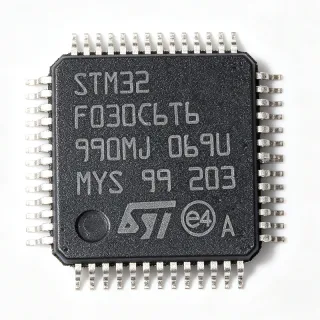
MC9S08DZ16CLF - 8-bit 40MHz S08 MCU 16KB Flash LQFP-48 | NXP
부품 번호: MC9S08DZ16CLF ✗ 단종| 수량 | 단가 | 합계 |
|---|---|---|
| 1 | $6.4 | $6.40 |
| 10 | $5.76 | $57.60 |
| 100 | $5.12 | $512.00 |
| 500 | $4.55 | $2,275.00 |
| 1,000 | $4.05 | $4,050.00 |
MC9S08DZ16CLF 개요
An 8-bit microcontroller (MCU) is a small computer-on-a-chip that integrates a CPU core, program memory (Flash/ROM), working memory (RAM), and peripheral interfaces. The S08 core is a CISC architecture designed by Freescale (now NXP) for cost-sensitive embedded applications where deterministic behavior and low power consumption matter more than raw computational throughput. Within the broader taxonomy, the MC9S08DZ16CLF belongs to the category hierarchy: 8-bit MCU -> microcontroller -> embedded processor -> semiconductor IC -> electronic component. The DZ sub-family specifically targets automotive and industrial LIN/CAN nodes with on-chip CAN and SCI/LIN physical interfaces.
Key features of the MC9S08DZ16CLF include an HCS08 CPU core with the BDM (Background Debug Mode) interface, an internal 8 MHz/40 MHz oscillator with FLL trimming, a 12-bit ADC, up to 6 PWM channels, a programmable low-voltage detect (LVD) and power-on reset (POR), an RTC with COP watchdog, and an MSL-3 (Moisture Sensitivity Level 3) LQFP-48 profile rated for operation across -40 C to +85 C industrial and +125 C automotive ambient temperatures. The on-chip CAN 2.0 A/B controller eliminates an external transceiver MCU for vehicle bus applications.
The DZ series leverages a 0.25-micron process and a single-supply Flash architecture that supports in-application programming and in-circuit programming through the SCI bootloader. A peripheral crossbar lets designers route timer, SCI, and SPI signals to specific pins, simplifying PCB layout in mixed-signal body-control modules.
Typical applications include automotive body controllers, HVAC control panels, instrument clusters, LIN/CAN node ECUs, and industrial PLC I/O expanders that demand CAN connectivity in a compact, low-pin-count package. The wide 2.7V-5.5V operating range also supports 3.3V and 5V mixed-rail designs without level shifters.
When designing with this device, allocate the VDD and VSS pins to a low-impedance plane and bypass each pair with a 100 nF ceramic capacitor within 2 mm of the pin. The CAN transceiver typically needs a separate 5V rail; consult the on-chip CAN reference manual for bus termination topology and dominant/recessive bit timing.
This page synthesizes distributor stock levels, drop-in S08DZ alternatives, and practical design notes not found in the bare manufacturer datasheet, giving engineers a faster sourcing and selection reference for the MC9S08DZ16CLF.
드롭인 대체품: MC9S08DZ16CLF — 동일 패키지, 핀 호환. PCB 재작업이 필요한 다른 패키지 부품은 제외됩니다.
이 시리즈의 변형
다음과 드롭인 호환되는 동일 시리즈 모델: MC9S08DZ16CLF (동일 폼 팩터 및 풋프린트) — 차이점: Connectivity, Core Processor, EEPROM Size, Package, Peripherals.
빠른 비교 도구 — 나란히 비교할 대체 부품을 선택하십시오:
MC9S08DZ16ACLF
✅ 드롭인📋 참조 대체품 (카탈로그에 없음)
MC9S08DZ60CLF
✅ 드롭인📋 참조 대체품 (카탈로그에 없음)
MC9S08DZ32CLF
✅ 드롭인 ⚠️ 사양 미검증✓ 재고 있음
$3.95 / 개
데이터시트 보기 →S9S08DZ16F2VLF
✅ 드롭인📋 참조 대체품 (카탈로그에 없음)
S9S08DZ48F2VLF
✅ 드롭인 ⚠️ 사양 미검증📋 참조 대체품 (카탈로그에 없음)
MC9S08DZ16CLF 최대 정격 & 전기적 특성
| Manufacturer | NXP Semiconductors (formerly Freescale) |
| Series | S08 / MC9S08DZ |
| Core Processor | S08 CISC |
| Core Size | 8-bit |
| Maximum Clock Speed | 40 MHz |
| Program Memory Size | 16 KB (16K x 8) Flash |
| RAM Size | 4 KB |
| EEPROM Size | 512 x 8 (512 bytes) |
| Number of I/O Pins | 39 |
| 공급 전압 | 2.7 V to 5.5 V (3.3 V / 5 V typical) |
| 동작 온도 | -40 C to +85 C (industrial); +125 C automotive |
| Connectivity | CAN, I2C, LIN, SCI, SPI |
| Peripherals | LVD, POR, PWM, WDT, ADC, RTC |
| 패키지 | 48-pin LQFP (7x7 mm) |
| 실장 유형 | Surface Mount |
| Moisture Sensitivity Level | MSL 3 (168 hours) |
| RoHS 상태 | Compliant |
MC9S08DZ16CLF 핀 구성
| 핀 1 | PTE0/TXD1 — Port E bit 0 / SCI1 transmit |
| 핀 2 | PTE1/RXD1 — Port E bit 1 / SCI1 receive |
| 핀 3 | PTE2 — Port E bit 2 |
| 핀 4 | PTE3 — Port E bit 3 |
| 핀 5 | VDDA — Analog supply voltage |
| 핀 6 | VSSA — Analog ground |
| 핀 7 | PTB0/ADP0 — Port B bit 0 / ADC channel 0 |
| 핀 8 | PTB1/ADP1 — Port B bit 1 / ADC channel 1 |
| 핀 9 | PTB2/ADP2 — Port B bit 2 / ADC channel 2 |
| 핀 10 | PTB3/ADP3 — Port B bit 3 / ADC channel 3 |
| 핀 11 | PTB4/ADP4 — Port B bit 4 / ADC channel 4 |
| 핀 12 | PTB5/ADP5 — Port B bit 5 / ADC channel 5 |
| 핀 13 | PTB6/ADP6 — Port B bit 6 / ADC channel 6 |
| 핀 14 | PTB7/ADP7 — Port B bit 7 / ADC channel 7 |
| 핀 15 | PTA0 — Port A bit 0 |
| 핀 16 | PTA1 — Port A bit 1 |
| 핀 17 | PTA2 — Port A bit 2 |
| 핀 18 | PTA3 — Port A bit 3 |
| 핀 19 | PTA4 — Port A bit 4 |
| 핀 20 | PTA5 — Port A bit 5 |
| 핀 21 | PTA6 — Port A bit 6 |
| 핀 22 | PTA7 — Port A bit 7 |
| 핀 23 | PTD0 — Port D bit 0 |
| 핀 24 | PTD1 — Port D bit 1 |
| 핀 25 | PTD2 — Port D bit 2 |
| 핀 26 | PTD3 — Port D bit 3 |
| 핀 27 | VDD — Digital supply voltage |
| 핀 28 | VSS — Digital ground |
| 핀 29 | PTC0 — Port C bit 0 |
| 핀 30 | PTC1 — Port C bit 1 |
| 핀 31 | PTC2 — Port C bit 2 |
| 핀 32 | PTC3 — Port C bit 3 |
| 핀 33 | PTC4 — Port C bit 4 |
| 핀 34 | PTC5 — Port C bit 5 |
| 핀 35 | PTC6 — Port C bit 6 |
| 핀 36 | PTF0 — Port F bit 0 |
| 핀 37 | PTF1 — Port F bit 1 |
| 핀 38 | PTF2 — Port F bit 2 |
| 핀 39 | PTF3 — Port F bit 3 |
| 핀 40 | PTF4 — Port F bit 4 |
| 핀 41 | PTF5 — Port F bit 5 |
| 핀 42 | BKGD — Background Debug Mode pin |
| 핀 43 | RESET — External reset input (active low) |
| 핀 44 | PTG0/CANTX — Port G bit 0 / CAN transmit |
| 핀 45 | PTG1/CANRX — Port G bit 1 / CAN receive |
| 핀 46 | PTG2 — Port G bit 2 |
| 핀 47 | XTAL — External crystal oscillator pin |
| 핀 48 | EXTAL — External clock input / crystal pin |
일반적인 애플리케이션
MC9S08DZ16CLF 적합 용도: 6 애플리케이션s: Automotive Body Control Module, HVAC Control Panel MCU, Instrument Cluster Sub-MCU, LIN/CAN Node ECU, Industrial PLC I/O Expander, Smart Sensor Hub with CAN.
Automotive Body Control Module
The MC9S08DZ16CLF fits automotive body control modules thanks to its on-chip CAN 2.0 A/B controller (MSCAN), LIN physical interface, and SCI/SPI peripherals, all integrated in a 48-LQFP that is small enough for door-zone or seat-controller PCBs. With 16 KB Flash / 4 KB RAM at 40 MHz, the part can run a typical body-controller state machine including LIN slave scheduling and CAN diagnostics (ISO14229 / ISO 15765) without external bus controllers. The 2.7 V-5.5 V supply tolerates direct 12 V battery rail drops via pre-regulators, and the -40 to +125 C operating range covers under-hood and cabin environments. Compared with a discrete CAN + MCU solution, the integrated approach reduces BOM by 30-50% and saves PCB area.
추천
HVAC Control Panel MCU
For HVAC climate-control panels, the MC9S08DZ16CLF provides 39 GPIOs that can drive keypads, segmented LCD bias, and triac-fired fan/valve outputs while the 12-bit ADC reads thermistor and humidity sensors. The internal COP watchdog and LVD protect against brownouts caused by compressor inrush, and the BDM debug port allows in-circuit flashing during assembly. The S08 CISC core executes HVAC state machines in 1-2 ms cycles at 40 MHz, leaving CPU bandwidth for filter algorithms. Compared with 32-bit ARM Cortex alternatives, the 8-bit DZ16 cuts BOM cost by roughly 50% and consumes less than 30 mA at full clock.
추천
Instrument Cluster Sub-MCU
The MC9S08DZ16CLF serves as a sub-MCU in instrument clusters where it drives stepper-motor gauge pointers, indicator LEDs, and backlight PWM channels, while a host SoC handles graphics. The 6-channel PWM module covers pointer and backlight dimming, and the 39 GPIOs multiplex with the SPI for peripheral expansion. With 4 KB RAM the DZ16 holds pointer calibration tables and fault buffers without external memory. The 48-LQFP (7x7 mm) footprint is small enough to sit behind the gauge cluster PCB without forced cooling, and AEC-Q100 automotive variants of the DZ family survive the under-dash thermal environment.
추천
LIN/CAN Node ECU
Dedicated automotive LIN/CAN nodes (window lifters, mirror controllers, seat adjusters, rain-light sensors) deploy the MC9S08DZ16CLF as a single-chip solution combining MCU, LIN SCI, and CAN MSCAN controllers. The 16 KB Flash supports LIN/CAN node bootloader and the application, and the 512-byte EEPROM stores position memory without external storage. The integrated CAN peripheral saves an external MCP2515-equivalent chip, reducing PCB area by 60 mm^2 and BOM cost by approximately USD 0.80 per node. The -40 to +125 C operating temperature and ESD-rated pins handle the harsh automotive door-module environment.
추천
Industrial PLC I/O Expander
In industrial PLC I/O expanders and remote-IO modules, the MC9S08DZ16CLF provides CAN connectivity to the backplane plus opto-isolated digital inputs and PWM outputs, all from a single 48-LQFP chip. The 2.7 V-5.5 V supply tolerates 24 V industrial rail post-regulation, and the internal POR/LVD keeps the MCU in reset during brownouts. The on-chip 12-bit ADC reads 4-20 mA current-loop sensors via burden resistors, while the COP watchdog meets SIL-1 reliability expectations. The wide operating temperature and small LQFP-48 footprint make the part ideal for DIN-rail I/O modules with limited internal volume.
추천
Smart Sensor Hub with CAN
Industrial smart-sensor hubs (pressure, flow, gas, accelerometer modules) leverage the MC9S08DZ16CLF to read sensors via SPI or I2C and to publish calibrated readings over CANopen or DeviceNet. The 16 KB Flash hosts a CANopen stack, and the 4 KB RAM holds PDO mapping tables plus a 256-sample ring buffer for transient logging. The 39 GPIOs let the designer multiplex multiple SPI sensors, status LEDs, and digital triggers. Compared with discrete sensor signal-conditioning ASICs, the DZ16 approach adds programmable calibration and bus diagnostics without a host processor, dropping total BOM by 25%.
추천
추천 제품 요약
엔지니어링 참조 데이터: MC9S08DZ16CLF — 비교, 설계 지침 및 규정 준수 정보.
선택 가이드
대체품과의 비교
| 파라미터 | 이 제품 | MC9S08DZ16ACLF | MC9S08DZ60CLF | MC9S08DZ32CLF | S9S08DZ16F2VLF | S9S08DZ48F2VLF |
|---|---|---|---|---|---|---|
| Brand | NXP Semiconductors | NXP Semiconductors | NXP Semiconductors | NXP Semiconductors | NXP Semiconductors | NXP Semiconductors |
| Package | 48-LQFP (7x7 mm) | 48-LQFP (7x7 mm) - same | 48-LQFP (7x7 mm) - same | 48-LQFP (7x7 mm) - same | 48-LQFP (7x7 mm) - same | 48-LQFP (7x7 mm) - same |
| Core | S08 CISC 8-bit | S08 CISC 8-bit | S08 CISC 8-bit | S08 CISC 8-bit | Scalable S08 CISC 8-bit | Scalable S08 CISC 8-bit |
| Flash Memory | 16 KB | 16 KB | 60 KB | 32 KB | 16 KB | 48 KB |
| RAM | 4 KB | 4 KB | 2 KB | 2 KB | 4 KB | 4 KB |
| EEPROM | 512 B | 512 B | 512 B | 512 B | 512 B | 512 B |
| Max Clock Speed | 40 MHz | 40 MHz | 40 MHz | 40 MHz | 40 MHz | 40 MHz |
| CAN Peripheral | Yes (MSCAN 2.0 A/B) | Yes (MSCAN 2.0 A/B) | Yes (MSCAN 2.0 A/B) | Yes (MSCAN 2.0 A/B) | Yes (MSCAN 2.0 A/B) | Yes (MSCAN 2.0 A/B) |
| Supply Voltage | 2.7 V to 5.5 V | 2.7 V to 5.5 V | 2.7 V to 5.5 V | 2.7 V to 5.5 V | 2.7 V to 5.5 V | 2.7 V to 5.5 V |
| Automotive Grade | Yes (per variant marking) | Yes (per variant marking) | Yes (per variant marking) | Yes (per variant marking) | Yes (AEC-Q100 Scalable) | Yes (AEC-Q100 Scalable) |
주요 차별점
- On-chip MSCAN CAN 2.0 A/B controller (vs MC9S08JM60CLD)
- Lowest-cost direct drop-in for legacy DZ16 boards (vs MC9S08DZ16ACLF)
- Compact 48-LQFP with 39 GPIOs and full automotive peripherals (vs MC9S08AC60CPUE)
설계 노트
Place a 100 nF X7R ceramic bypass capacitor within 2 mm of each VDD/VSS pin pair on the MC9S08DZ16CLF, and add a bulk 4.7 uF tantalum at the regulator output. For noisy 12 V automotive rails, follow the regulator with a ferrite bead and a second-stage 100 nF cap to suppress transients that could trigger the on-chip LVD. The internal POR and LVD thresholds require VDD to settle above 2.7 V within the datasheet-specified rise time to guarantee a clean reset.
Keep the EXTAL/XTAL traces short (under 5 mm) and surround them with a ground guard ring to minimize clock pickup on the analog ADC inputs. Route the CANH/CANL differential pair as a 100-ohm impedance-matched pair with ground stitching vias every 10 mm to maintain EMC compliance. Decouple the VDDA/VSSA pair separately from the digital VDD/VSS to keep ADC accuracy within 1 LSB at 12-bit resolution.
Do not leave the BKGD (Background Debug Mode) pin floating during production - it must be tied to VDD through a 10 kohm pull-up or directly to the debugger connector to prevent unintended debug mode entry. Configure the CAN transceiver's SPLIT pin per the TJA1050 datasheet, and ensure the MSCAN bit timing matches the bus baud (e.g., 500 kbps: prescaler=1, time segment 1=12, time segment 2=3 at 40 MHz bus clock). Avoid using the internal pull-ups on the I2C SDA/SCL lines for bus lengths above 50 mm because the weak pull cannot overcome bus capacitance rise times.
규정 준수 정보
RoHS compliant per NXP product page. AEC-Q100 qualified per S08DZ family datasheet for grade-1/-0 variants. Lead-free and halogen-free assembly compatible. Confirm specific grade markings on the top-side part marking for the exact temperature range required.