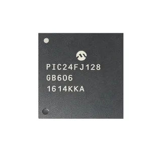
PIC32MX534F064HT-I/MR - 80MHz 32-bit MCU 64KB Flash USB/CAN | Microchip
부품 번호: PIC32MX534F064HT-I/MR ✓ 활성| 수량 | 단가 | 합계 |
|---|---|---|
| 1 | $5.96 | $5.96 |
| 10 | $5.36 | $53.60 |
| 100 | $4.77 | $477.00 |
| 500 | $4.06 | $2,030.00 |
| 1,000 | $3.42 | $3,420.00 |
PIC32MX534F064HT-I/MR 개요
A PIC32MX microcontroller is a 32-bit MIPS-based general-purpose MCU from Microchip's PIC32 family, bridging the gap between 8/16-bit PIC microcontrollers and high-end Cortex-M parts. The PIC32MX5xx sub-family specifically targets USB- and CAN-equipped designs, layering Full-Speed USB On-The-Go, a dedicated DMA engine for offloading the engine to peripherals, and a parallel bus for memory-mapped external devices. It sits within the broader hierarchy of MCU -> 32-bit MCU -> MIPS MCU -> PIC32MX family -> PIC32MX5xx sub-family. This positioning explains its widespread use in industrial control, USB peripherals, and CAN-networked sensors where a higher-performance 32-bit core is required without the cost of Cortex-M4 parts.
Key features that differentiate this MCU include a 1.25 ns MIPS M4K core pipeline supporting 1.53 DMIPS/MHz and a deterministic interrupt controller, a 10-bit ADC with up to 16 channels and 1 Msps conversion rate, and code-protection Flash with the standard PIC16/32 instruction-set architecture that allows many existing PIC firmware libraries to be ported. The 16 KB RAM is sufficient for moderate USB-class stacks, including CDC, HID, and MSD, while the 64 KB Flash supports full TCP/IP or USB stacks alongside user application code.
The PIC32MX534F064H variant also includes a 10-bit ADC, four-wire JTAG for boundary-scan debugging, and two comparators. Its integrated USB 2.0 Full-Speed On-The-Go controller eliminates the need for an external PHY, simplifying BOM cost in human-interface and data-acquisition designs. The 80 MHz core with single-cycle flash prefetch is sufficient for sustained 60+ MIPS operation, and the dedicated DMA engine offloads data movement between peripherals and memory, leaving the core free for application logic.
Typical applications for the PIC32MX534F064HT-I/MR include USB human-interface devices (HID) like keyboards and touchscreens, CAN-bus industrial sensor nodes, USB-to-UART bridges, mid-range data loggers, embedded web servers running lwIP or Microchip Harmony TCP/IP, and motor-control feedback processors. Its industrial temperature grade makes it suitable for factory automation nodes and white-goods modes.
When designing with this MCU, ensure the VQFN exposed pad is soldered to a sufficient copper pour for thermal dissipation, and add 100 nF decoupling capacitors adjacent to every supply pin. The USB DP/DM traces must be routed as a 90-ohm differential pair on the PCB, and the CAN bus must be terminated with a 120-ohm resistor at each end of the segment.
This page synthesizes distributor pricing, drop-in same-package alternatives from the PIC32MX5xx family, and practical engineering guidance not found in the standalone datasheet, giving procurement and design engineers a consolidated reference for the PIC32MX534F064HT-I/MR.
드롭인 대체품: PIC32MX534F064HT-I/MR — 동일 패키지, 핀 호환. PCB 재작업이 필요한 다른 패키지 부품은 제외됩니다.
이 시리즈의 변형
다음과 드롭인 호환되는 동일 시리즈 모델: PIC32MX534F064HT-I/MR (동일 폼 팩터 및 풋프린트) — 차이점: ADC, Package, USB, DMA Channels, Core Architecture.
빠른 비교 도구 — 나란히 비교할 대체 부품을 선택하십시오:
PIC32MX534F064H-I/MR
✅ 드롭인✓ 재고 있음
$5.2 / 개
데이터시트 보기 →PIC32MX534F128HT-I/MR
✅ 드롭인📋 참조 대체품 (카탈로그에 없음)
PIC32MX534F064HT-V/MR
✅ 드롭인📋 참조 대체품 (카탈로그에 없음)
PIC32MX470F512H-I/MR
✅ 드롭인✓ 재고 있음
$5.08 / 개
데이터시트 보기 →PIC32MX430F064H-I/MR
✅ 드롭인📋 참조 대체품 (카탈로그에 없음)
PIC32MX450F256H-I/MR
✅ 드롭인📋 참조 대체품 (카탈로그에 없음)
PIC32MX534F064HT-I/MR 최대 정격 & 전기적 특성
| Core Architecture | MIPS32 M4K 32-bit RISC |
| Maximum CPU Speed | 80 MHz |
| Program Memory (Flash) | 64 KB (64K x 8) |
| Data Memory (SRAM) | 16 KB (16K x 8) |
| Operating Voltage Range | 2.3 V to 3.6 V |
| I/O Pins | 53 |
| ADC | 10-bit, 1 Msps, up to 16 channels |
| USB | USB 2.0 Full-Speed Device/Host/OTG |
| CAN | CAN 2.0B |
| DMA Channels | 4 |
| Timers | 5 x 16-bit |
| UART | 2 |
| SPI | 2 |
| I2C | 2 |
| Comparators | 2 |
| JTAG | Yes |
| 패키지 | 64-pin VQFN (MR) 9x9 mm with exposed pad |
| 동작 온도 | -40C to +85C (industrial) |
| RoHS 상태 | Compliant |
PIC32MX534F064HT-I/MR 핀 구성
| 핀 1 | RB0 — I/O port B bit 0 (CN2/RB0) |
| 핀 2 | RB1 — I/O port B bit 1 (CN3/RB1) |
| 핀 3 | RB2 — I/O port B bit 2 (CN4/RB2) |
| 핀 4 | RB3 — I/O port B bit 3 (CN5/RB3) |
| 핀 5 | VSS — Ground reference |
| 핀 6 | RB4 — I/O port B bit 4 (CN6/RB4) |
| 핀 7 | RB5 — I/O port B bit 5 (CN7/RB5) |
| 핀 8 | RB6 — I/O port B bit 6 (ICDCLK/RB6) |
| 핀 9 | RB7 — I/O port B bit 7 (ICDDAT/RB7) |
| 핀 10 | RB8 — I/O port B bit 8 (CN8/RB8) |
| 핀 11 | RB9 — I/O port B bit 9 (CN9/RB9) |
| 핀 12 | RB10 — I/O port B bit 10 (CN10/RB10) |
| 핀 13 | RB11 — I/O port B bit 11 (CN11/RB11) |
| 핀 14 | RB12 — I/O port B bit 12 (CN12/RB12) |
| 핀 15 | RB13 — I/O port B bit 13 (CN13/RB13) |
| 핀 16 | RB14 — I/O port B bit 14 (CN14/RB14) |
| 핀 17 | RB15 — I/O port B bit 15 (CN15/RB15) |
| 핀 18 | VSS — Ground reference |
| 핀 19 | VDD — Digital supply voltage (3.3V) |
| 핀 20 | RA0 — I/O port A bit 0 |
| 핀 21 | RA1 — I/O port A bit 1 |
| 핀 22 | RA2 — I/O port A bit 2 |
| 핀 23 | RA3 — I/O port A bit 3 |
| 핀 24 | RA4 — I/O port A bit 4 |
| 핀 25 | RA5 — I/O port A bit 5 |
| 핀 26 | RA6 — I/O port A bit 6 |
| 핀 27 | RA7 — I/O port A bit 7 |
| 핀 28 | VSS — Ground reference |
| 핀 29 | VDD — Digital supply voltage (3.3V) |
| 핀 30 | RA9 — I/O port A bit 9 |
| 핀 31 | RA10 — I/O port A bit 10 |
| 핀 32 | RA11 — I/O port A bit 11 |
| 핀 33 | RA12 — I/O port A bit 12 |
| 핀 34 | RA13 — I/O port A bit 13 |
| 핀 35 | RA14 — I/O port A bit 14 |
| 핀 36 | RA15 — I/O port A bit 15 |
| 핀 37 | RC0 — I/O port C bit 0 |
| 핀 38 | RC1 — I/O port C bit 1 |
| 핀 39 | RC2 — I/O port C bit 2 |
| 핀 40 | VSS — Ground reference |
| 핀 41 | RC4 — I/O port C bit 4 |
| 핀 42 | RC5 — I/O port C bit 5 |
| 핀 43 | RC6 — I/O port C bit 6 |
| 핀 44 | RC7 — I/O port C bit 7 |
| 핀 45 | RC8 — I/O port C bit 8 |
| 핀 46 | RC9 — I/O port C bit 9 |
| 핀 47 | RC10 — I/O port C bit 10 |
| 핀 48 | RC11 — I/O port C bit 11 |
| 핀 49 | RC12 — I/O port C bit 12 |
| 핀 50 | RC13 — I/O port C bit 13 |
| 핀 51 | RC14 — I/O port C bit 14 |
| 핀 52 | RC15 — I/O port C bit 15 |
| 핀 53 | VSS — Ground reference |
| 핀 54 | VDD — Digital supply voltage (3.3V) |
| 핀 55 | RD0 — I/O port D bit 0 |
| 핀 56 | RD1 — I/O port D bit 1 |
| 핀 57 | RD2 — I/O port D bit 2 |
| 핀 58 | RD3 — I/O port D bit 3 |
| 핀 59 | RD4 — I/O port D bit 4 |
| 핀 60 | RD5 — I/O port D bit 5 |
| 핀 61 | RD6 — I/O port D bit 6 |
| 핀 62 | RD7 — I/O port D bit 7 |
| 핀 63 | RD8 — I/O port D bit 8 |
| 핀 64 | RD9 — I/O port D bit 9 |
일반적인 애플리케이션
PIC32MX534F064HT-I/MR 적합 용도: 7 애플리케이션s: USB Human Interface Device (HID), CAN-Bus Industrial Sensor Node, USB-to-UART Bridge, Embedded Web Server with lwIP TCP/IP, Motor Control Feedback Processor, USB Data Acquisition Module, Industrial Touchscreen HMI Controller.
USB Human Interface Device (HID)
The PIC32MX534F064HT-I/MR is well-suited for USB HID designs such as keyboards, mice, touchscreens, and custom input devices, thanks to its integrated Full-Speed USB 2.0 On-The-Go controller with on-chip PHY that eliminates the need for an external transceiver. The 80 MHz MIPS M4K core executes the HID class driver with substantial performance margin, while 64 KB Flash holds the USB stack plus custom HID report descriptors. The 64-pin VQFN package exposes enough I/O for key-scan matrices, LED indicators, and capacitive-touch sensing inputs. Compared to a Cortex-M0+ alternative, the PIC32MX5xx offers USB certification heritage and Microchip's mature Harmony USB stack, reducing firmware development risk. For keyboard applications, the 16 KB SRAM supports USB endpoint buffering plus a keyboard matrix-scan buffer; the 10-bit ADC can decode rotary encoders or analog joystick inputs in gaming controllers.
추천
CAN-Bus Industrial Sensor Node
The PIC32MX534F064HT-I/MR's integrated CAN 2.0B controller makes it ideal for industrial CAN-bus sensor nodes such as temperature, pressure, and flow transmitters. The 80 MHz core can sustain CAN message rates up to 1 Mbit/s while still running application-level processing, and the 16 KB SRAM holds CAN driver buffers plus protocol stacks like CANopen or J1939. The industrial -40C to +85C operating range covers factory floor environments, while the 64-pin VQFN package provides enough I/O for sensor interfaces including I2C sensors, SPI ADCs, and analog front-ends. Compared to a discrete MCU plus external CAN controller, the integrated approach reduces BOM cost by 30-40%. The four DMA channels offload ADC-to-memory transfers in high-speed sensor sampling, leaving the core free to handle CAN message processing without timing jitter.
추천
USB-to-UART Bridge
The PIC32MX534F064HT-I/MR's Full-Speed USB and dual UART peripherals make it well-suited for USB-to-UART bridge designs such as debug serial ports, industrial bridges, and legacy device networking adapters. The integrated USB PHY simplifies PCB design, while the two UARTs allow bridging between USB and two independent RS-232/RS-485 ports at speeds up to 20 Mbaud. The 80 MHz core handles USB CDC-ACM class drivers plus protocol conversion (e.g., Modbus RTU to USB) with adequate headroom. The 64 KB Flash accommodates the USB CDC stack plus application-layer protocol firmware; the 16 KB SRAM supports 64-byte USB endpoint buffers plus UART FIFOs. The industrial temperature range supports factory automation bridges, while the 64-pin VQFN footprint exposes GPIOs for status LEDs, mode selection, and configuration DIP switches.
추천
Embedded Web Server with lwIP TCP/IP
The PIC32MX534F064HT-I/MR can run the lwIP TCP/IP stack for industrial Ethernet gateways, remote sensor monitoring, and SCADA nodes when paired with an SPI Ethernet controller like the ENC28J60 or the on-board USB-to-Ethernet bridge. The 80 MHz MIPS M4K core sustains HTTP server throughput for small JSON/XML payloads, while the 64 KB Flash fits lwIP plus application firmware. The 16 KB SRAM is tight for TCP/IP buffers - designs requiring sustained high-throughput Ethernet should consider the PIC32MX534F128HT-I/MR with 32 KB RAM. The 64-pin VQFN exposes enough I/O for SPI Ethernet, status LEDs, and configuration buttons. The industrial temperature grade supports factory-floor deployments, and the integrated USB enables dual-mode Ethernet-over-USB operation for diagnostic and configuration ports.
추천
Motor Control Feedback Processor
The PIC32MX534F064HT-I/MR's 10-bit 1 Msps ADC and four DMA channels make it suitable as a feedback processor for low-end motor control designs such as BLDC sensor monitoring and stepper driver interfaces. The ADC can sample three-phase current shunts at high speed via DMA without CPU intervention, leaving the core free for control loop calculation. The 80 MHz MIPS M4K core executes PI/PID loops with sub-microsecond loop times, while the 5 x 16-bit timers provide PWM edge alignment and quadrature encoder interfaces for BLDC rotor position sensing. The 64 KB Flash holds sensorless control algorithms plus USB diagnostic channels for parameter tuning; the 16 KB SRAM supports lookup tables for sine/cosine commutation. The industrial temperature grade supports industrial motor drives operating in -40C to +85C environments.
추천
USB Data Acquisition Module
The PIC32MX534F064HT-I/MR's 10-bit 1 Msps ADC with up to 16 input channels and integrated USB 2.0 Full-Speed makes it an excellent fit for USB-based data acquisition modules for test & measurement, instrumentation, and laboratory equipment. The ADC with DMA offload can stream 16 channels at 50 ksps aggregate without CPU intervention, while the USB isochronous or bulk endpoint streams samples to the host PC. The 80 MHz core handles USB class driver plus optional on-device FIR/IIR filtering; the 64 KB Flash holds USB stack plus calibration tables. The 16 KB SRAM supports double-buffered sample streams; the 64-pin VQFN package exposes up to 16 ADC inputs plus USB, UART, and I2C for sensor interfacing. Compared to Cortex-M0+ alternatives, the PIC32MX5xx offers superior ADC performance and integrated USB for true plug-and-play operation.
추천
Industrial Touchscreen HMI Controller
The PIC32MX534F064HT-I/MR's combination of USB, 10-bit ADC, and 80 MHz MIPS core makes it suitable as a controller for industrial touchscreen HMI panels with USB-CDC command interfaces. The 64 KB Flash holds the USB stack plus the HMI graphics protocol parser, while the 16 KB SRAM supports display frame buffer region plus USB endpoint buffers. The 10-bit ADC can decode analog joystick or rotary dial inputs alongside the digital touch controller interface via SPI. The 64 pins provide ample GPIO for backlight PWM, status indicators, and serial configuration interfaces. The -40C to +85C industrial temperature range supports factory floor HMI installations. Compared to higher-end Cortex-M4 parts, the PIC32MX5xx offers a more cost-effective solution when advanced HMI features like graphics acceleration are not required.
추천
추천 제품 요약
엔지니어링 참조 데이터: PIC32MX534F064HT-I/MR — 비교, 설계 지침 및 규정 준수 정보.
선택 가이드
대체품과의 비교
| 파라미터 | 이 제품 | PIC32MX534F064H-I/MR | PIC32MX534F128HT-I/MR | PIC32MX534F064HT-V/MR | PIC32MX470F512H-I/MR | PIC32MX430F064H-I/MR | PIC32MX450F256H-I/MR |
|---|---|---|---|---|---|---|---|
| Package | VQFN-64 (MR) 9x9 mm | VQFN-64 (MR) 9x9 mm - same | VQFN-64 (MR) 9x9 mm - same | VQFN-64 (MR) 9x9 mm - same | VQFN-64 (MR) 9x9 mm - same | VQFN-64 (MR) 9x9 mm - same | VQFN-64 (MR) 9x9 mm - same |
| Brand | Microchip Technology | Microchip Technology - same | Microchip Technology - same | Microchip Technology - same | Microchip Technology - same | Microchip Technology - same | Microchip Technology - same |
| Core Architecture | MIPS32 M4K 32-bit | MIPS32 M4K 32-bit | MIPS32 M4K 32-bit | MIPS32 M4K 32-bit | MIPS32 M4K 32-bit | MIPS32 M4K 32-bit | MIPS32 M4K 32-bit |
| Maximum CPU Speed | 80 MHz | 80 MHz | 80 MHz | 80 MHz | 120 MHz | 80 MHz | 80 MHz |
| Flash Memory | 64 KB | 64 KB | 128 KB | 64 KB | 512 KB | 64 KB | 256 KB |
| SRAM | 16 KB | 16 KB | 32 KB | 16 KB | 64 KB | 16 KB | 32 KB |
| USB | USB 2.0 FS OTG | USB 2.0 FS OTG | USB 2.0 FS OTG | USB 2.0 FS OTG | USB 2.0 FS OTG | No USB | No USB |
| CAN | CAN 2.0B | CAN 2.0B | CAN 2.0B | CAN 2.0B | CAN 2.0B | No CAN | No CAN |
| Operating Temperature | -40C to +85C | -40C to +85C | -40C to +85C | -40C to +105C | -40C to +85C | -40C to +85C | -40C to +85C |
주요 차별점
- Same-footprint higher-memory drop-in upgrade path (vs PIC32MX534F064H-I/MR (without 'T'))
- Integrated USB 2.0 FS OTG + CAN 2.0B eliminates external peripherals (vs PIC32MX430F064H-I/MR)
- Extended temperature range option on identical footprint (vs PIC32MX470F512H-I/MR)
설계 노트
The PIC32MX534F064HT-I/MR in the 64-pin VQFN (MR) 9x9 mm package dissipates power primarily through the central exposed thermal pad (EP). At 80 MHz full activity the typical core current is 30-60 mA at 3.3V, giving 100-200 mW dissipation. The exposed pad MUST be thermally tied to a copper pour (recommended at least 1 square inch of 1 oz copper on top layer, plus thermal vias to inner planes) to keep junction temperature within the -40C to +85C industrial specification. Without the thermal pad properly soldered, junction-to-ambient thermal resistance can rise by 30-50%, causing thermal shutdown or long-term reliability degradation.
Place 100 nF X7R ceramic decoupling capacitors on every VDD pin (pins 19, 29, 54) as close to the package as possible, with traces shorter than 3 mm to minimize inductance. Add a 10 uF bulk capacitor near the MCU to handle switching transients. For USB applications, route the DP (D+) and DM (D-) traces as a 90-ohm differential pair with matched length and continuous ground reference plane; cross-overs should be perpendicular, never parallel, and the pair should not be split over different PCB layers.
Route the USB DP/DM lines away from high-frequency switching nodes (DC-DC converters, oscillator traces) by at least 3 mm and keep the total length under 50 mm to meet USB signal integrity requirements. Place the 15 kohm pull-down resistor on the D- line (for full-speed device detection) within 2 mm of the connector. For CAN bus applications, route CANH and CANL as a 120-ohm differential pair with similar length-matching discipline, and place the MCP2551 transceiver within 25 mm of the MCU CAN pins.
Do NOT operate the PIC32MX534F064HT-I/MR outside the 2.3 V to 3.6 V supply range - the internal 1.8 V regulator and Flash read paths require minimum 2.3 V for proper operation, and exceeding 3.6 V risks latchup. The MCLR reset pin must NOT be left floating; it requires a 10 kohm pull-up to VDD for normal operation. Failure to configure the JTAG/Trace pins (RB6/RB7) as JTAG (not GPIO) at reset will prevent ICD3/PICkit 5 debug access. The 'T' suffix indicates tape-and-reel packaging orientation; confirm the orientation code matches your pick-and-place setup before high-volume assembly.
For high-speed USB Full-Speed operation at 12 Mbps, the DP/DM signal edges have ~10 ns rise time; maintain 90-ohm differential impedance with ±10% tolerance and continuous ground reference to control common-mode noise. Place the USB series ferrite bead or common-mode choke within 10 mm of the connector to suppress EMI. The 48 MHz internal PLL for USB requires the 8 MHz external crystal or oscillator to have 50 ppm initial accuracy and 50 ppm stability over temperature to stay within USB 2.0 specification.
규정 준수 정보
RoHS compliant per Microchip product page. Industrial temperature range -40C to +85C. AEC-Q100 not applicable for general industrial MCU; contact Microchip for AEC-Q100-qualified automotive PIC32 variants.