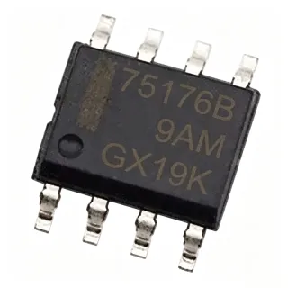
SP720ABTG-L - 14-Input ESD TVS Array | Littelfuse
부품 번호: SP720ABTG-L ✗ 단종| 수량 | 단가 | 합계 |
|---|---|---|
| 1 | $1.2947 | $1.29 |
| 10 | $1.2993 | $12.99 |
| 100 | $0 | $0.00 |
| 500 | $0 | $0.00 |
| 1,000 | $0 | $0.00 |
SP720ABTG-L 개요
What is a TVS diode array? A TVS diode array is a semiconductor protection component placed between an external signal or bus line and sensitive circuitry. It diverts transient current away from the protected device while allowing normal low-voltage logic signals to pass. The SP720 family uses SCR/diode bipolar protection structures, with two structures associated with each input according to the Littelfuse datasheet.
The verified product information identifies 14 available input-protection channels, surface mounting, and a 16-SOIC package. A distributor listing describes the related SP720ABTG variant as a mixed-technology TVS device with 14 circuits and a 16-SOIC package. The SP720ABTG-L ordering suffix is treated as the specified Littelfuse variant; electrical details beyond the supplied verified values are not independently expanded here.
SP720 protection is appropriate for general-purpose logic protection, data buses, communication interfaces, and other exposed external lines where ESD transients can enter through connectors or cables. The array format provides centralized protection in one package, reducing the number of individual discrete protection devices required when several lines need protection.
Placement close to the board entry point or connector is important because the protective device must intercept the transient before it propagates into the protected logic. Trace geometry, return paths, grounding, and the choice between the array and a discrete low-capacitance solution should be checked against the signal speed and operating requirements.
This page combines the verified Littelfuse and distributor information with practical placement guidance and clearly marks unavailable specifications. Review the manufacturer datasheet and application note AN9734 before production release, especially for system-level ESD validation, signal integrity, and the exact electrical limits of the ordered suffix.
드롭인 대체품: SP720ABTG-L — 동일 패키지, 핀 호환. PCB 재작업이 필요한 다른 패키지 부품은 제외됩니다.
이 시리즈의 변형
다음과 드롭인 호환되는 동일 시리즈 모델: SP720ABTG-L (동일 폼 팩터 및 풋프린트).
빠른 비교 도구 — 나란히 비교할 대체 부품을 선택하십시오:
SP720ABTG
✅ 드롭인✓ 재고 있음
$1.2947 / 개
데이터시트 보기 →SP720ABT
✅ 드롭인📋 참조 대체품 (카탈로그에 없음)
SP720AP
✅ 드롭인📋 참조 대체품 (카탈로그에 없음)
SP720ABG
✅ 드롭인📋 참조 대체품 (카탈로그에 없음)
SP720AB
✅ 드롭인📋 참조 대체품 (카탈로그에 없음)
SP720ABTG-L 사양
| Product Type | TVS diode array |
| Protection Function | ESD and over-voltage protection |
| Available Inputs | 14 inputs |
| Protection Structures | 2 SCR/diode bipolar structures per input |
| Input Pins | Pins 1-7 and 9-15 |
| Reference Pins | V+ and V- |
| Protection Path | IN to V+ or V- |
| 패키지 | 16-SOIC |
| 실장 유형 | Surface mount |
| Related SP720ABTG Voltage | 30 V |
| Related SP720ABTG Current | 1 A |
| Related SP720ABTG Capacitance | 3 pF |
| Related SP720ABTG Input Count | 14 inputs |
| Related SP720ABTG-L Suppression Voltage | 35 V (SUP) |
| Related SP720ABTG-L Input Current | 2 A (I (IN)) |
| Related SP720ABTG-L Thermal Resistance | 130THRM RES |
| Series | SP720 Lead-Free/Green Series |
SP720ABTG-L 핀 구성
| 핀 1 | IN — Protected input according to Littelfuse datasheet |
| 핀 2 | IN — Protected input according to Littelfuse datasheet |
| 핀 3 | IN — Protected input according to Littelfuse datasheet |
| 핀 4 | IN — Protected input according to Littelfuse datasheet |
| 핀 5 | IN — Protected input according to Littelfuse datasheet |
| 핀 6 | IN — Protected input according to Littelfuse datasheet |
| 핀 7 | IN — Protected input according to Littelfuse datasheet |
| 핀 8 | V- — Negative protection reference according to manufacturer description; exact pin label confirmation required |
| 핀 9 | IN — Protected input according to Littelfuse datasheet |
| 핀 10 | IN — Protected input according to Littelfuse datasheet |
| 핀 11 | IN — Protected input according to Littelfuse datasheet |
| 핀 12 | IN — Protected input according to Littelfuse datasheet |
| 핀 13 | IN — Protected input according to Littelfuse datasheet |
| 핀 14 | IN — Protected input according to Littelfuse datasheet |
| 핀 15 | IN — Protected input according to Littelfuse datasheet |
| 핀 16 | V+ — Positive protection reference according to manufacturer description; exact pin label confirmation required |
일반적인 애플리케이션
SP720ABTG-L 적합 용도: 6 애플리케이션s: General-Purpose Logic Protection, Data-Bus Input Protection, Communication Interface Protection, Connector-Based ESD Protection, Low-Voltage Control-System Inputs, Embedded System Bus Protection.
General-Purpose Logic Protection
The Littelfuse SP720ABTG-L is a 14-input TVS diode array designed to protect sensitive logic lines from ESD and over-voltage transients. Its array construction allows several external digital inputs to share one protection package, which can simplify board protection planning compared with many discrete devices. Littelfuse identifies two SCR/diode bipolar structures per input and protection from the IN pins to V+ or V-. Place the array near connector or board-entry points so the transient is intercepted before it reaches the protected logic. The verified package is 16-SOIC, and the exact suffix ratings should be confirmed against the Littelfuse datasheet before production release.
추천
Data-Bus Input Protection
SP720ABTG-L can protect multiple data-bus inputs when the system needs centralized transient suppression. The verified Littelfuse description identifies 14 available inputs and identifies pins 1-7 and 9-15 as the protected IN connections, with V+ and V- providing the protection references. This arrangement is useful where a connector exposes multiple low-voltage digital lines to user contact or cable-borne ESD. The designer must still verify signal voltage, capacitance, and timing because the supplied data does not establish every electrical limit for the -L suffix. Route the protected traces directly to the array and keep the surge-current loop compact.
추천
Communication Interface Protection
The Littelfuse SP720ABTG-L is applicable to communication interfaces whose external conductors can receive ESD transients. Its 14-channel array format can protect multiple input conductors at a connector boundary while leaving the protected circuitry referenced to V+ and V-. The array is especially appropriate for low-voltage, multi-line interfaces where a centralized package is easier to route than many individual protection components. The selected device's capacitance and clamp behavior must be checked against the interface bandwidth; the verified supplier snippet for related SP720ABTG lists 3 pF, while exact -L values remain to be confirmed from the manufacturer datasheet.
추천
Connector-Based ESD Protection
Use SP720ABTG-L at a board connector boundary to intercept ESD before it reaches sensitive logic. The verified manufacturer description states that protection is directed from the IN pins to V+ or V-, and the component is available in a surface-mount 16-SOIC package. This makes it a practical centralized protection choice when a connector exposes many input lines. Correct placement is essential: the array should be close to the connector, with short protection paths and a low-inductance return to the board reference. Validate the assembled design against the intended ESD system-level test and the Littelfuse application note AN9734.
추천
Low-Voltage Control-System Inputs
The SP720ABTG-L can serve as an input-protection network for industrial or embedded control boards that receive external control or status signals. Fourteen inputs allow several separate lines to be grouped in one 16-SOIC footprint while maintaining individual transient paths to V+ and V-. The part is intended for ESD and over-voltage protection rather than power conversion or signal conditioning. Confirm that every external signal remains below the verified working-voltage limits and that the protection reference pins are connected according to the manufacturer diagram. The supplied data does not provide a full temperature range or complete electrical table for the exact -L suffix.
추천
Embedded System Bus Protection
SP720ABTG-L can be placed at the entry point of an embedded-system bus when multiple microcontroller or peripheral lines leave a board through an exposed connector. The 14-input structure provides a single package for protecting the external side of the bus, while the protected circuitry remains isolated by correct routing and reference connections. This arrangement helps prevent an ESD event from propagating into processor pins or peripheral interfaces. Because the verified results do not provide the complete -L pin table, capacitance, or dynamic-resistance values, engineers should use the official SP720 datasheet and compare those parameters with the bus edge rate before finalizing the layout.
추천
추천 제품 요약
엔지니어링 참조 데이터: SP720ABTG-L — 비교, 설계 지침 및 규정 준수 정보.
선택 가이드
대체품과의 비교
| 파라미터 | 이 제품 | SP720ABTG | SP720ABT | SP720AP | SP720ABG | SP720AB |
|---|---|---|---|---|---|---|
| Brand | Littelfuse | Littelfuse | Littelfuse | Littelfuse | Littelfuse | Littelfuse |
주요 차별점
- 14-input protection density (vs NUP4301MR6T1G)
- Centralized 16-SOIC footprint (vs SP720ABTG)
- Dedicated SCR/diode structures (vs Generic discrete TVS diode)
- Related -L listing voltage distinction (vs SP720ABTG)
설계 노트
Place the SP720ABTG-L at the connector or board-entry boundary, with the IN traces reaching the protection pins before any sensitive circuitry. Keep the protection path short and route the transient return toward V+ and V- through low-inductance connections. The manufacturer states that protection is from the IN pins, pins 1-7 and 9-15, to V+ or V-, so the PCB layout should preserve that topology rather than treating the array as a generic two-terminal TVS.
Review the exact capacitance and dynamic resistance from the official SP720ABTG-L datasheet before using the array on high-speed lines. A related SP720ABTG distributor snippet lists 3 pF, but that value was not confirmed for the -L suffix and may be unsuitable for a given edge rate. Compare the protection-device capacitance with the receiver, connector, and trace capacitance, then validate the completed board with the intended signaling standard.
Do not assume that SP720ABTG and SP720ABTG-L are electrically identical. The supplied listings associate the non-L part with 30 V and 1 A, while the -L listing reports 35 V (SUP) and 2 A (I (IN)). Confirm the exact suffix, package, pinout, working voltage, clamp behavior, and environmental ratings in the Littelfuse datasheet before substituting parts or releasing a production BOM.
Use the Littelfuse application note AN9734 and system-level ESD guidance to select the protection reference connection and verify the complete transient path. ESD protection effectiveness depends not only on the diode array but also on connector return continuity, chassis or board grounding, trace geometry, and the speed of the protected interface. Validate with the actual cable, enclosure, and system-level ESD test configuration.
규정 준수 정보
Littelfuse identifies the SP720 family as Lead-Free/Green Series. RoHS and REACH status for the exact SP720ABTG-L suffix were not explicitly provided; a separate related-part result states ROHS3 compliant for SP720ABTG, but this is not treated as proof for the -L suffix.