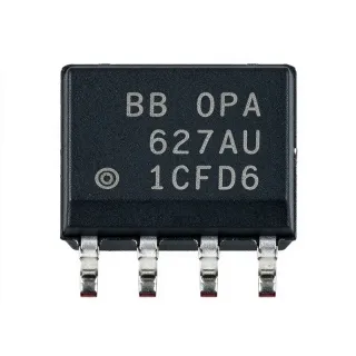
LM2903VQDR - Dual Differential Comparator | Texas Instruments
MPN: LM2903VQDR ✓ AktifLM2903VQDR Ringkasan
A differential comparator is an analog integrated circuit that compares two input voltages and produces a digital logic state indicating which input is higher. The LM2903V belongs to the comparator hierarchy: differential comparator, voltage comparator, analog comparator, and ultimately semiconductor. Its two channels allow one packaged device to perform two independent threshold decisions, reducing component count when a system requires multiple sensing or control functions.
The device operates from a 2 V minimum supply to a 36 V maximum supply, giving it broad compatibility with industrial control voltages. The distributor specifications identify an input bias current of 0.5 nA and a supply current of 0.8 mA. Its open-collector outputs can sink output current from external pull-up circuitry, and the 8-pin SOIC package supports conventional surface-mount assembly and automated inspection.
The enhanced-voltage LM2903V family is intended for applications that benefit from wide supply-voltage operation and low input bias current. A high-impedance input stage can limit loading on slow sensor signals, while the open-collector output provides flexibility in voltage-domain interfacing. Because the output transistor is open, the external pull-up voltage can be selected independently within the design's logic constraints.
Typical uses include industrial process-limit detection, automotive and battery-powered control systems, motor and relay interfaces, window-comparator circuits, and low-frequency sensor conditioning. In a threshold circuit, one input can receive the sensed voltage and the other can receive a reference. The output changes state when their relationship crosses the configured threshold, allowing the result to drive another logic stage or an external transistor.
Design the pull-up network carefully because it determines output voltage, rise time, and available sink current. Place the pull-up resistor close to the open-collector output, keep comparator inputs away from switching-current paths, and provide a stable reference with low noise when threshold accuracy matters. The open-collector pins can also be tied together for wired-AND behavior when the circuit requires multiple fault signals to share one node.
This product page combines device specifications, application guidance, drop-in replacement options, and parameter-by-parameter comparison information. It helps engineers determine whether the LM2903VQDR's voltage range, low input bias current, open-collector interface, and extended temperature coverage match the mechanical and electrical requirements of a specific PCB design.
Pilihan pengganti yang segera untuk LM2903VQDR — sama paket, pin-pin kompatibel. Bahagian paket yang berbeza memerlukan kerja ulang PCB diasingkan.
Varietas dalam siri ini
Model serupa yang kompatibel dengan pengganti yang segera LM2903VQDR (sama faktor bentuk dan kaki) — berbeza dalam Input Bias Current, Supply Current, Number of Channels, Output Type, Operating Temperature Range.
LM2903QDRQ1
✅ Masuk Drop-InHubungi untuk harga
Lihat Datasheet →LM2903BIDR
✅ Masuk Drop-InHubungi untuk harga
Lihat Datasheet →LM2903VQDR
✅ Masuk Drop-InHubungi untuk harga
Lihat Datasheet →LM2903DT
✅ Masuk Drop-In📋 Alternatif rujukan (tidak dalam katalog)
LM2903DQ
✅ Masuk Drop-In📋 Alternatif rujukan (tidak dalam katalog)
LM2903VQDR Penilaian maksimum & Ciri-ciri Elektrik
| Comparator Type | Dual differential comparator |
| Number of Channels | 2 channels |
| Supply Voltage Range | 2 V to 36 V |
| Jenis Output | Open-collector |
| Input Bias Current | 0.5 nA |
| Arus Pemberi Arus | 0.8 mA |
| Offset Voltage | 370 uV |
| Gambaran Suhu Operasi | -40°C to +125°C |
| Package Type | SOIC (D), 8 pins |
| Package Pin Count | 8 pins |
| Jenis Pemasangan | Surface mount |
| Comparator Class | Enhanced voltage |
| Output Wiring | Open-collector wired-logic output |
Konfigurasi Pin LM2903VQDR
| Pin 1 | OUT1 — Open-collector output for comparator channel 1 |
| Pin 2 | IN1- — Inverting input for comparator channel 1 |
| Pin 3 | IN1+ — Non-inverting input for comparator channel 1 |
| Pin 4 | V- — Ground or negative supply connection |
| Pin 5 | IN2+ — Non-inverting input for comparator channel 2 |
| Pin 6 | IN2- — Inverting input for comparator channel 2 |
| Pin 7 | OUT2 — Open-collector output for comparator channel 2 |
| Pin 8 | V+ — Positive supply connection |
Aplikasi Biasa
LM2903VQDR patut untuk 6 aplikasis: Industrial Sensor Threshold Detection, Automotive Control and Logic Interface, Relay and Actuator Interfacing, Battery-Powered Monitoring, Power-Supply Window Monitoring, Zero-Cross and Level Detection.
Industrial Sensor Threshold Detection
The LM2903VQDR is well suited to comparing a low-current sensor signal with a reference voltage because each channel provides 0.5 nA input bias current and operates from 2 V to 36 V. Place the sensed voltage on one input and the threshold reference on the other, then use the open-collector output to alert a controller or request a relay action. The low bias current limits input loading, while the wide supply range supports industrial control voltages. The main design consideration is input common-mode range: both inputs must remain within the comparator's permitted operating region at every supply voltage and temperature.
Disebarkan
Automotive Control and Logic Interface
The LM2903VQDR's -40°C to +125°C operating range makes it applicable to automotive control, battery monitoring, and actuator-logic circuits where temperature variation is significant. Its dual-channel arrangement can independently monitor a system signal and a safety threshold, reducing board area. The open-collector output can pull up to the logic rail through a resistor or drive a suitable transistor. Designers should confirm common-mode limits, output current, ESD requirements, and automotive qualification requirements for the complete assembly rather than relying only on the temperature rating.
Disebarkan
Relay and Actuator Interfacing
The LM2903VQDR can generate a low-side control signal for relay, solenoid, or motor-driver circuitry through its open-collector output. Place a pull-up resistor on the output so the comparator can sink the logic current, then connect the collector to an N-channel MOSFET or NPN transistor gate or base. This arrangement keeps the inductive load away from the comparator and permits the pull-up voltage to match the controller logic domain. Add a flyback diode across the coil and verify the output sink-current and voltage ratings in the manufacturer datasheet.
Disebarkan
Battery-Powered Monitoring
The LM2903VQDR is useful for battery-powered monitoring because it accepts a 2 V minimum supply and has a stated 0.8 mA supply current for the dual device. Two channels can monitor pack voltage and a secondary threshold, helping implement simple overvoltage, undervoltage, or state-of-charge decisions. The open-collector output can remain unpowered or be pulled to a low-power logic rail, depending on the system architecture. Ensure that the comparator's quiescent current, input leakage, and reference circuit consumption are acceptable for the target standby-time budget.
Disebarkan
Power-Supply Window Monitoring
The two LM2903VQDR channels can implement upper and lower thresholds for a monitored power rail. One comparator channel detects the rail crossing above the upper limit, while the other detects operation below the lower limit. Using the open-collector outputs with pull-up resistors allows the resulting states to be combined for fault signaling. The 2 V to 36 V device supply range supports monitoring of widely distributed voltage rails, but the monitored input must stay within the comparator's common-mode limits. Account for input offset when defining guard bands around critical thresholds.
Disebarkan
Zero-Cross and Level Detection
The LM2903VQDR can detect when a bipolar or offset signal crosses a configurable reference level. Use the appropriate input polarity so the output state identifies whether the signal is above or below the threshold, and add positive feedback or hysteresis when noise near the transition could otherwise cause repeated switching. Its 0.5 nA input bias current is helpful for high-impedance signal sources, while the open-collector output supports flexible pull-up arrangements. Check input common-mode voltage, output timing, and the pull-up resistor's effect on rise time.
Disebarkan
Ringkasan Produk Disebarkan
Data referensi kejuruteraan untuk LM2903VQDR — perbandingan, panduan rancangan, dan maklumat kesediaan
Panduan Pilihan
Perbandingan dengan Gantian
| Parametr | Produk Ini | LM2903QDR | LM2903BIDR | LM2903VQDR | LM2903DT | LM2903DQ |
|---|---|---|---|---|---|---|
| Brand | Texas Instruments | Texas Instruments | Texas Instruments | ROHM Semiconductor | STMicroelectronics | 3PEAK |
| Package | SOIC-8 | SOIC-8 | SOIC-8 | SOIC-8 | SOIC-8 | SOIC-8 |
| Number of Channels | 2 channels | 2 channels | 2 channels | 2 channels | 2 channels | 2 channels |
Penyeberangsung Jelas
- Wide 36 V maximum supply rating (vsLM2903DT)
- Low 0.5 nA input bias current (vsLM2903BIDR)
- Dual channels in an 8-pin SOIC footprint (vsLM2903DQ)
- Wide-temperature operation (vsLM2903QDR)
Catatan Desain
Do not treat the open-collector outputs as push-pull logic outputs. Each OUT pin requires a pull-up resistor to the intended logic rail unless it drives a transistor input. Confirm that the available sink current is sufficient and that the pull-up value produces the required output rise time. Also verify that both comparator inputs remain inside the allowable common-mode range at the lowest and highest supply voltages.
Place the output pull-up resistor close to OUT1 or OUT2 to minimize trace capacitance and keep the switching return current short. Route the two input pairs away from relay-coil wiring, switching-power nodes, and high-current return paths. If a precision reference is used, keep its ground connection compact and use a low-value bypass capacitor where compatible with the reference circuit.
Add hysteresis with positive feedback when a slow or noisy signal can cross the threshold repeatedly. The hysteresis voltage adds directly to the switching point, so select the resistor values from the intended noise margin rather than using a generic value. Also account for comparator offset and input error when setting upper and lower detection limits.
The dual device is specified at 0.8 mA supply current, but total system consumption also includes the pull-up network, reference circuit, and external driver. Use the lowest pull-up resistance that still satisfies output sink-current and timing requirements. For battery-powered operation, calculate standby current at the highest anticipated temperature because device consumption can vary with supply voltage and temperature.
Maklumat Kesediaan
No explicit compliance declaration for LM2903VQDR was identified. Confirm current material and environmental compliance documentation with the manufacturer before production release.