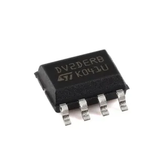
ATR4253-EK - FM Antenna Amplifier Eval Kit | Microchip
MPN: ATR4253-EK ✓ Active| Qty | Unit Price | Extended |
|---|---|---|
| 1 | $0 | $0.00 |
| 10 | $0 | $0.00 |
| 100 | $0 | $0.00 |
| 500 | $0 | $0.00 |
| 1,000 | $0 | $0.00 |
ATR4253-EK Overview
An RF evaluation board is a hardware development platform that lets designers characterize an RF/antenna IC's performance without designing a custom PCB first. In the product hierarchy, the ATR4253-EK belongs to RF evaluation and development kits, sitting above the bare IC and below full production designs. Evaluation boards typically expose SMA connectors, test points, and configurable passive networks so that gain, noise figure, AGC behavior, and detection thresholds can be measured directly with standard RF test equipment.
Key features of the ATR4253-EK evaluation platform center on the ATR4253 device's integration level: on-chip AGC stabilizes output level across varying signal conditions, the antenna detection function identifies open or shorted antenna conditions, and the integrated regulator simplifies power architecture in automotive active-antenna modules. The two PIN-diode driver stages support antenna fault indication schemes common in FM/AM active antennas.
Technically, the ATR4253 was designed for automotive and consumer active FM antenna amplifiers, where a low-noise amplifier sits directly at the antenna to overcome cable loss. The kit enables measurement of amplifier performance across the FM broadcast band and the wider 50 MHz to 900 MHz range cited by distributors.
Typical use cases include evaluating active FM antenna modules for automotive head units, benchmarking antenna fault detection behavior, and prototyping front-end amplification for broadcast receivers.
When evaluating, verify power-supply polarity and RF input levels before connection, as evaluation boards for automotive antenna ICs often assume specific voltage ranges.
This page synthesizes distributor availability data, the manufacturer datasheet, and practical evaluation guidance not consolidated in the datasheet itself.
Drop-in alternatives for ATR4253-EK — same package, pin-to-pin compatible. Different-package parts requiring PCB rework are excluded.
Quick Comparison Tool — Select alternative parts for side-by-side comparison:
No drop-in alternatives available for this product.
Request AlternativesATR4253-EK Specifications (manufacturer-published)
| Product Type | Evaluation Kit (RF Evaluation and Development Kits, Boards) |
| Associated Device | ATR4253 |
| Function | FM Antenna Amplifier Evaluation |
| Frequency Range | 50 MHz to 900 MHz |
| Amplifier Features | Built-in AGC, antenna detection, power supply regulator, two PIN diode driver stages |
| Part Status | Active |
| Factory Lead Time | 9 Weeks |
| Packaging | Bulk |
| RoHS Status | RoHS Compliant |
| Lead Free Status | Lead Free |
ATR4253-EK Interfaces & Connectors
No manufacturer-published interface list is available for ATR4253-EK. Refer to the manufacturer documentation for connector and header details.
Refer to the manufacturer documentation for the full expansion header pinout and connector pin numbering.
Typical Applications
ATR4253-EK is suitable for 6 applications: Automotive Active FM Antenna Development, Broadcast Receiver Front-End Prototyping, RF Test and Measurement Bench Characterization, Antenna Fault Detection Scheme Evaluation, Educational and Training RF Labs, IoT and Telematics Tuner Integration.
Automotive Active FM Antenna Development
The ATR4253-EK directly supports development of automotive active FM antenna modules, the primary use case for the ATR4253 IC. The device's integrated antenna detection and two PIN-diode driver stages implement the open/short fault indication demanded by automotive head-unit diagnostics, while the built-in power supply regulator conditions vehicle supply rails. Engineers use the kit to measure amplifier gain across the FM band (87.5-108 MHz) within the wider 50 MHz to 900 MHz coverage, characterize AGC settling under varying signal conditions, and validate fault-flag thresholds before committing to a production PCB. Because the evaluation board presents standard RF interfaces, gain and noise measurements can be made with a vector network analyzer or spectrum analyzer without custom fixtures, shortening the path from evaluation to design-in for antenna amplifier modules in vehicles.
Recommended
Broadcast Receiver Front-End Prototyping
For consumer radio, set-top, and tuner designers, the ATR4253-EK serves as a rapid front-end prototyping platform. Placing a low-noise active amplifier at the antenna overcomes downstream coaxial cable loss, which can reach several dB in typical installations and directly degrades SNR. The kit lets designers measure gain flatness across the FM broadcast band and confirm that the ATR4253's AGC keeps output level stable under strong local stations while weak-signal sensitivity is preserved. The 50 MHz to 900 MHz operating range also leaves headroom for evaluating weather-band or adjacent VHF services on the same hardware. By tuning external matching networks on the evaluation board, engineers can quantify how source impedance affects gain and noise figure prior to final layout.
Recommended
RF Test and Measurement Bench Characterization
Test benches benefit from the ATR4253-EK as a known-good reference for characterizing active antenna chains. The board's standard RF connectors allow direct cascading with signal generators, noise figure meters, and spectrum analyzers across the 50 MHz to 900 MHz span. Engineers can use it to benchmark the ATR4253's AGC transfer characteristic by sweeping input level and recording output regulation, and to exercise antenna detection logic by deliberately opening or shorting the antenna port to observe fault behavior. Because the kit is RoHS compliant, lead free, and actively manufactured (9-week factory lead time, Active status), labs can standardize on it for repeatability. Documented results from the kit then serve as acceptance criteria for custom PCB spins of the same amplifier circuit.
Recommended
Antenna Fault Detection Scheme Evaluation
A distinctive capability of the ATR4253-EK is evaluating antenna fault detection schemes before production. The ATR4253 integrates antenna detection plus two driver stages for external PIN diodes - a topology used to signal antenna open-circuit or short-circuit conditions to the host system, a requirement in automotive antenna diagnostics. Using the evaluation board, engineers can inject fault conditions (disconnected antenna, shorted feedline) and measure detection response time and flag thresholds. The PIN-diode driver outputs can be probed to verify they switch correctly under DC fault current levels. This characterization establishes the external component values (diode choice, bias resistors) that will carry into the production design, de-risking the diagnostic feature that end customers perceive as antenna quality.
Recommended
Educational and Training RF Labs
The ATR4253-EK fits university and corporate training labs teaching RF front-end concepts. Because the board integrates AGC, detection, regulation, and driver stages on one platform, students can observe multiple RF system behaviors - automatic gain control, active antenna noise trade-offs, fault signaling - on a single evaluation kit spanning 50 MHz to 900 MHz. Standard RF test equipment interfaces mean exercises run on generic lab instruments without custom fixtures. The kit's Active lifecycle status and RoHS compliance keep it procutable through normal university purchasing channels, though the 9-week factory lead time and quote-based secondary distribution mean courses should order material a semester ahead. Measurement results from the board map directly onto lecture topics such as noise figure, gain compression, and AGC loop dynamics.
Recommended
IoT and Telematics Tuner Integration
Telematics units, fleet trackers, and connected-car gateways increasingly include FM/broadcast reception for emergency channels and infotainment. The ATR4253-EK lets designers of such IoT devices validate that an active antenna front-end based on the ATR4253 meets receiver sensitivity targets despite compact, lossy antenna placements. Measurements on the kit quantify gain added at the antenna and confirm AGC stability when the vehicle transitions between strong urban signals and rural weak-signal zones. Antenna detection output can be wired to the host MCU as a diagnostic input, so the platform's fault signaling integrates with telematics health monitoring. Evaluating on the kit across 50 MHz to 900 MHz also verifies out-of-band behavior relevant to coexisting cellular or GNSS antennas in dense vehicle installations.
Recommended
Recommended Products Summary
Engineering reference data for ATR4253-EK — comparison, design guidance, and compliance information.
Selection Guide
Comparison with Alternatives
| Parameter | This Product |
|---|---|
| Product Type | Evaluation kit for ATR4253 |
| Brand | Microchip Technology |
| Frequency Range | 50 MHz to 900 MHz |
| Associated IC | ATR4253 |
| Package | Evaluation board (no IC package) |
| Part Status | Active |
| RoHS | Compliant |
| Lead Time | 9 weeks factory; distributor stock at DigiKey |
Key Differentiators
- High integration on a single evaluation platform (vs Custom ATR4253 breadboard circuit)
- Wide 50 MHz to 900 MHz evaluation coverage (vs FM-band-only evaluation modules)
- Actively manufactured and compliant (vs Legacy discontinued antenna-amplifier evaluation boards)
Design Notes
The ATR4253-EK is a development tool, not a production component. Do not place the -EK part number in a production BOM; design in the ATR4253 IC itself and replicate the datasheet reference circuit. During evaluation, verify supply polarity and RF input drive level before connection - antenna amplifier evaluation boards can be damaged by ESD at the antenna port or by overdriving the input beyond the AGC control range, which masks the very AGC and detection behaviors the kit is meant to characterize.
When translating evaluation results to your own PCB, reproduce the kit's RF layout practices: short, controlled-impedance 50-ohm traces from the antenna connector to the ATR4253 input, solid ground plane, and input matching components placed at the IC pin. Gain flatness measured on the evaluation board between 50 MHz and 900 MHz will only transfer to your layout if trace inductance at the amplifier input and PIN-diode driver routing are kept comparable to the reference design.
Characterize AGC and antenna-detection behavior with controlled input sweeps. Drive the kit from a calibrated signal generator, sweep input level over the expected FM antenna signal range, and log output level plus detection flag state. Because the ATR4253 integrates two PIN-diode driver stages for fault signaling, verify flag thresholds under realistic DC bias rather than ideal lab conditions, so the production diagnostic firmware is calibrated against measured, not assumed, thresholds.
Compliance Information
RoHS Compliant and Lead Free per DigChip datasheet summary. REACH, halogen-free, and conflict-minerals status not stated in retrieved data.