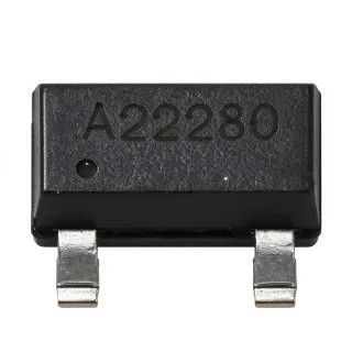
CDSOT23-T24CAN-Q - 24V CAN Bus TVS, 40V Clamp, AEC-Q101 | Bourns
MPN: CDSOT23-T24CAN-Q ✓ Active| Qty | Unit Price | Extended |
|---|---|---|
| 1 | $0.62 | $0.62 |
| 10 | $0.48 | $4.80 |
| 100 | $0.31 | $31.00 |
| 500 | $0.24 | $120.00 |
| 1,000 | $0.19 | $190.00 |
CDSOT23-T24CAN-Q Overview
A TVS (Transient Voltage Suppressor) diode is a circuit-protection semiconductor that clamps transient overvoltage events, such as electrostatic discharge (ESD) and surge transients, by avalanche breakdown before they can damage sensitive transceiver circuitry. Within the protection hierarchy, TVS diode arrays sit at the board level of a layered protection strategy, complementing chip-level protection integrated inside the CAN transceiver itself. Arrays like this one integrate two TVS elements in a single package so that both lines of a differential bus are protected by one component.
Key features include the dual bidirectional topology purpose-built for CANH and CANL differential lines, a minimum breakdown voltage of 26.2 V that guarantees the device will not conduct during a 24 VDC power-cross miswiring event, and a 40 V clamping voltage at the 8 A (8/20 us) surge level. The AEC-Q101 qualification ensures reliability under automotive stress conditions.
The device uses avalanche breakdown diode technology with a low-clamping, fast-response characteristic. Because the protection elements are bidirectional, they clamp negative transients symmetrically on both CAN lines, protecting the transceiver differential I/O against ISO 7637-style and IEC 61000-4-5 style surge events referenced in Bourns CANbus application notes.
Typical applications include automotive CAN bus nodes, body control modules, industrial CANopen and DeviceNet networks, and 24V truck and off-highway vehicle bus systems where 24 V power miswiring tolerance is mandatory.
Design consideration: place the TVS array as close as possible to the connector with short, wide low-inductance traces to ground so the clamping path stays effective at fast transient edge rates.
This page synthesizes distributor availability, verified drop-in alternatives, and practical CAN protection design guidance not found in the manufacturer datasheet.
Drop-in alternatives for CDSOT23-T24CAN-Q — same package, pin-to-pin compatible. Different-package parts requiring PCB rework are excluded.
Variants in this series
Same-series models that are drop-in compatible with CDSOT23-T24CAN-Q (same form factor and footprint) — differing in Number of Protected Lines, Clamping Voltage, Mounting Type, Package, Peak Pulse Current (Ipp).
Quick Comparison Tool — Select alternative parts for side-by-side comparison:
CDSOT23-T24CAN
✅ Drop-In📋 Reference alternative (not in catalog)
CDSOT23-T24CAN-Q-ES
✅ Drop-In📋 Reference alternative (not in catalog)
PESD2CAN,215
✅ Drop-In✓ In Stock
$0.09 / Unit
View Datasheet →PESD2CAN
✅ Drop-In✓ In Stock
$0.05 / Unit
View Datasheet →CDSOT23-T24CAN-Q Specifications
| Product Type | Dual bidirectional TVS diode array (CANbus protector) |
| Peak Pulse Current (Ipp) | 8 A (8/20 us) |
| Clamping Voltage | 40 V |
| Minimum Breakdown Voltage (VBR) | 26.2 V |
| Application | 24V CANbus protection |
| Number of Protected Lines | 2 (CANH and CANL) |
| Direction Type | Bidirectional |
| Package | SOT-23-3 |
| Mounting Type | Surface Mount |
| Automotive Qualification | AEC-Q101 qualified |
| RoHS Status | RoHS Compliant |
CDSOT23-T24CAN-Q Pin Configuration
| Pin 1 | CANH I/O — Bidirectional TVS anode/cathode terminal connected to CANH line |
| Pin 2 | GND — Common cathode ground terminal |
| Pin 3 | CANL I/O — Bidirectional TVS anode/cathode terminal connected to CANL line |
Safe Operating Area
Typical Applications
CDSOT23-T24CAN-Q is suitable for 6 applications: Automotive CAN Bus Node Protection, 24V Truck and Off-Highway Vehicle J1939 Networks, Industrial CANopen and DeviceNet Equipment, CAN Gateway and Body Control Modules, ESD and Surge Protection Test Reference Design, Building Automation and Elevator Control CAN Buses.
Automotive CAN Bus Node Protection
The CDSOT23-T24CAN-Q fits automotive CAN nodes directly because it is AEC-Q101 qualified and purpose-built for the CANH/CANL differential pair, with a 40 V clamp at 8 A (8/20 us) absorbing load-dump and switching transients defined in Bourns CANbus application notes. It is placed between the connector and the transceiver differential I/O, ahead of the 120 ohm termination network, so surge energy is diverted before reaching the transceiver. Because both TVS elements share one SOT-23-3 footprint, the board area penalty is a single 3-pad land pattern. Design trade-off: the 26.2 V minimum breakdown means the device never conducts during normal 12V or 24V bus signaling, but designers must still verify that the transceiver absolute maximum ratings exceed the 40 V clamp level.
Recommended
24V Truck and Off-Highway Vehicle J1939 Networks
SAE J1939 heavy-duty truck and off-highway systems run on 24V supplies where miswiring to the 24 V rail is a realistic fault. The CDSOT23-T24CAN-Q addresses this exactly: per the Bourns datasheet, its minimum breakdown voltage of 26.2 V ensures the TVS will not conduct during a 24 VDC power-cross event, so it survives miswiring that would destroy lower-voltage CAN protectors. The 40 V clamping voltage then limits residual transient voltage to a level that 24V-rated transceivers with internal miswiring circuitry tolerate. Use one package per CAN interface to protect both lines symmetrically. The trade-off is that its higher breakdown makes it unsuitable for low-voltage single-ended buses, so keep it dedicated to differential CAN/CAN-FD style interfaces at 24V systems.
Recommended
Industrial CANopen and DeviceNet Equipment
Industrial CAN networks in factories suffer cable-induced ESD and coupled surges from adjacent motor drives. The CDSOT23-T24CAN-Q protects the differential CANH/CANL lines with its 8 A (8/20 us) Ipp rating and 40 V clamp, absorbing the transient before it reaches the transceiver die. Although the -Q part is automotive-screened, that extra robustness is a benefit in harsh industrial environments; the non-Q CDSOT23-T24CAN offers the same electrical performance at lower cost when automotive qualification is not required. Mount the array at the connector, with a solid chassis-referenced ground, and keep the stub between connector and TVS under a few millimeters so inductance does not degrade clamping. Bourns CANbus application notes provide reference protection topologies for exactly this use case.
Recommended
CAN Gateway and Body Control Modules
Gateway modules bridge multiple CAN channels, multiplying exposure to transients on external connectors. Each CAN channel of a gateway or body control module can be protected by one CDSOT23-T24CAN-Q package, whose dual bidirectional array covers both lines of that channel with a single SOT-23-3 footprint, minimizing board area in dense multi-channel designs. The AEC-Q101 qualification simplifies automotive quality sign-off for tier-one customers. Place each TVS at its own connector, not at the MCU, because clamping effectiveness falls with trace inductance. The 26.2 V minimum breakdown also protects against 24 V jump-start miswiring on 12V passenger-vehicle harnesses, one of the most common field failures in body electronics. Verify transceiver clamp ratings versus the 40 V maximum clamping voltage during design.
Recommended
ESD and Surge Protection Test Reference Design
The Bourns datasheet includes a surge test setup showing the differential input/output of a typical CAN transceiver with its termination network protected by the CDSOT23-T24CAN-Q, making this part a natural fit for qualification test boards and reference designs. Engineers validating against system-level transient requirements can reproduce the documented topology: transceiver I/O to termination network, TVS array at the connector side, and an 8/20 us surge generator applied differentially. The measured residual voltage should remain below the 40 V clamp rating while the 8 A peak pulse current flows through the device. Using the exact datasheet-recommended part removes a validation variable, and the same footprint accommodates the non-Q variant for cost-reduction studies after qualification is complete.
Recommended
Building Automation and Elevator Control CAN Buses
Elevator controllers, HVAC rooftop units, and building automation backbones frequently use CAN or CAN-derived buses with long cable runs through electrically noisy shafts and plant rooms. The CDSOT23-T24CAN-Q's 8 A (8/20 us) surge capability and 40 V clamp give these long, exposed runs robust protection, while the 26.2 V minimum breakdown keeps the TVS transparent to normal differential signaling around 2-5 V amplitude. Because industrial buildings can also see 24V control-wiring miswiring, the power-cross immunity is a practical benefit, not just an automotive nicety. One SOT-23-3 package per bus protects both conductors, and the array's bidirectional clamping handles both positive and negative transient polarities encountered from inductive loads sharing cable trays.
Recommended
Recommended Products Summary
Engineering reference data for CDSOT23-T24CAN-Q — comparison, design guidance, and compliance information.
Selection Guide
Comparison with Alternatives
| Parameter | This Product | CDSOT23-T24CAN | CDSOT23-T24CAN-Q-ES | PESD2CAN,215 | PESD2CAN |
|---|---|---|---|---|---|
| Package | SOT-23-3 | SOT-23-3 - same | SOT-23 - same | SOT-23 - same footprint | SOT-23 - same footprint |
| Brand | Bourns | Bourns | Bourns | Nexperia | Nexperia |
| Application | 24V CANbus protection | 24V CANbus protection | 24V CANbus protection | CAN bus ESD protection | CAN bus ESD protection |
| RoHS Compliance | Compliant | Compliant | Compliant | Compliant | Compliant |
Key Differentiators
- Guaranteed 24 VDC power-cross immunity (vs Generic 24V CAN TVS parts)
- AEC-Q101 automotive qualification (vs CDSOT23-T24CAN (non-Q))
- Dual array in single SOT-23-3 footprint (vs PESD2CAN,215 (Nexperia))
Design Notes
Place the CDSOT23-T24CAN-Q as close to the CAN connector as possible, ahead of the 120 ohm termination network shown in the Bourns datasheet surge test setup. Total trace length between connector and TVS should be only a few millimeters with wide traces, because each nanohenry of series inductance adds L*di/dt overshoot on top of the 40 V clamp during the 8 A (8/20 us) surge. Use a solid, low-impedance ground connection at pin 2; do not route the TVS ground through a thin signal trace.
The 26.2 V minimum breakdown is intentional: the device must not conduct during a 24 VDC power-cross event per the Bourns datasheet. Do not substitute a lower-breakdown generic 24V TVS, as it will latch into conduction and may be destroyed by sustained miswiring current. Conversely, verify that the CAN transceiver absolute maximum pin voltage exceeds the 40 V clamping voltage, otherwise residual clamp voltage can still damage the transceiver during a full 8 A surge.
Surge energy handling depends on pulse duration: the 8 A Ipp rating is specified for the 8/20 us waveform. For longer-duration surges such as those described in Bourns CANbus application notes or IEC 61000-4-5 style tests, derate the allowable current - the allowable surge current scales down roughly with the square root of the pulse-width ratio. For systems requiring higher energy absorption, add a series PTC or common-mode choke upstream of the TVS to limit sustained fault current into the array.
Compliance Information
RoHS compliant per DigiKey listing. AEC-Q101 qualified (discrete semiconductor automotive standard, per Mouser and Bourns AEC-Q101 product directory). REACH and halogen-free declarations not stated in retrieved data - consult Bourns product page for full material declarations.