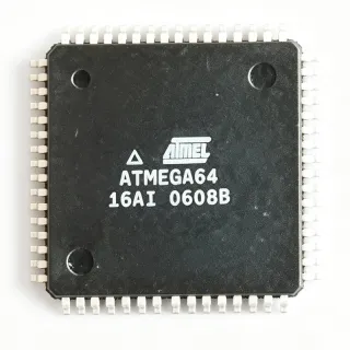
DSPIC33EP256GM604-H/PT - 70 MIPS 256KB DSC | Microchip Technology
MPN: DSPIC33EP256GM604-H/PT ✓ Active| Qty | Unit Price | Extended |
|---|---|---|
| 1 | $6.42 | $6.42 |
| 10 | $5.78 | $57.80 |
| 100 | $5.14 | $514.00 |
| 500 | $4.62 | $2,310.00 |
| 1,000 | $4.16 | $4,160.00 |
DSPIC33EP256GM604-H/PT Overview
A digital signal controller combines the computational architecture of a microcontroller with the DSP engine of a digital signal processor. Built on a Harvard architecture, the dsPIC33E core executes instructions and data fetches in parallel, making it well suited to real-time control loops where deterministic interrupt latency matters. In the system hierarchy it sits between general-purpose MCUs and dedicated DSPs, targeting precision embedded control.
Key features include the 70 MIPS dsPIC DSC core with integrated DSP multiply-accumulate instructions, dual on-chip operational amplifiers, CAN peripheral support for automotive and industrial networking, and a dual-channel 12-bit ADC family architecture that feeds sensor data directly into control loops. These peripherals reduce external component count in motor-drive and power-conversion designs.
Technically, the 85.5K x 24 instruction-word Flash organization reflects the 24-bit instruction width of the dsPIC core. On-chip DSP resources and hardware multiply/divide support fast digital filtering, transforms, and field-oriented control mathematics without burdening the CPU. Enhanced peripherals offload timing-critical tasks such as PWM generation for three-phase inverters.
Typical applications include precision sensorless and sensored motor control (BLDC, PMSM, stepper), digital power supplies and solar inverters, and automotive body or powertrain subsystems that leverage the AEC-Q100 qualification and CAN bus.
Design consideration: as a 3.3V-only device, level shifting is required when interfacing with 5V logic, and all VDD/VSS pairs must be decoupled and the ICSP pair (PGECx/PGEDx) kept consistent for programming.
This page synthesizes distributor pricing context, drop-in same-family alternatives, and practical design notes not found in a single manufacturer datasheet.
Drop-in alternatives for DSPIC33EP256GM604-H/PT — same package, pin-to-pin compatible. Different-package parts requiring PCB rework are excluded.
Variants in this series
Same-series models that are drop-in compatible with DSPIC33EP256GM604-H/PT (same form factor and footprint) — differing in Package, Supply Voltage, Core Architecture, Flash Program Memory, Operating Temperature.
Quick Comparison Tool — Select alternative parts for side-by-side comparison:
DSPIC33EP256GM604-I/PT
✅ Drop-In ⚠️ Specs Unverified✓ In Stock
$3.86 / Unit
View Datasheet →DSPIC33EP128GM304-H/PT
✅ Drop-In ⚠️ Specs Unverified📋 Reference alternative (not in catalog)
DSPIC33EP64GM304-H/PT
✅ Drop-In ⚠️ Specs Unverified📋 Reference alternative (not in catalog)
DSPIC33EP256GP604-H/PT
✅ Drop-In ⚠️ Specs Unverified📋 Reference alternative (not in catalog)
DSPIC33EP128MU504-H/PT
✅ Drop-In ⚠️ Specs Unverified✓ In Stock
$4.48 / Unit
View Datasheet →DSPIC33EP256GM604-H/PT Maximum Ratings & Electrical Characteristics
| Core Architecture | 16-bit dsPIC33E DSC, Harvard |
| Maximum CPU Speed | 70 MIPS |
| Flash Program Memory | 256KB (85.5K x 24) |
| Supply Voltage | 3.3 V |
| Series | dsPIC 33EP (dsPIC33EP256GM604) |
| Qualification | Automotive, AEC-Q100 |
| Package | 44-TQFP (10 x 10 mm) |
| Pin Count | 44 |
| Mounting Type | Surface Mount |
| Packaging | Tray |
| Peripherals | On-chip OpAmps, CAN, DSP engine |
| ADC | Dual-channel 12-bit (family architecture) |
| Typical Application Domain | Motor control, digital power, automotive |
| On-Chip Operational Amplifiers | Yes (integrated) |
| CAN Interface | Yes |
DSPIC33EP256GM604-H/PT 44-tqfp (10 x 10 mm) Pin Configuration Guide
Pin configuration for DSPIC33EP256GM604-H/PT (44-tqfp (10 x 10 mm) package). This digital IC includes GPIO, communication interfaces (UART, SPI, I2C), and power pins. Refer to the manufacturer datasheet for alternate pin functions and configuration options. Essential for embedded system design and PCB layout.

No detailed pinout data available for DSPIC33EP256GM604-H/PT.
Refer to the datasheet for full pin configuration.
Typical Applications
DSPIC33EP256GM604-H/PT is suitable for 6 applications: Precision Motor Control (BLDC/PMSM), Automotive Electronic Control Units, Digital Power Supplies and Solar Inverters, Industrial Automation and Robotics, Sensor Signal Acquisition and DSP Data Logging, Embedded Control Prototyping and OEM Products.
Precision Motor Control (BLDC/PMSM)
The DSPIC33EP256GM604-H/PT fits precision motor control because its 70 MIPS 16-bit DSP core executes field-oriented control (FOC) algorithms with deterministic latency, while the dual-channel 12-bit ADC samples phase currents at control-loop rates and the on-chip operational amplifiers condition shunt-resistor signals without external op-amps. In a typical PMSM drive, the DSC runs the current loop at 10-20 kHz, generating complementary PWM outputs from the enhanced PWM module with dead-time insertion in hardware. The 256KB Flash accommodates sensorless estimators, communication stacks, and fault logging simultaneously. Using this controller in a single-chip inverter reduces BOM cost and board area versus discrete signal-chain solutions, and AEC-Q100 qualification covers automotive traction and pump applications.
Recommended
Automotive Electronic Control Units
The DSPIC33EP256GM604-H/PT is AEC-Q100 qualified, making it appropriate for automotive ECUs such as body controllers, HVAC blowers, fuel-pump drivers, and throttle actuators. The integrated CAN peripheral connects the node to the vehicle network while the 70 MIPS core runs local closed-loop control with the dual-channel 12-bit ADC acquiring sensor feedback. On-chip operational amplifiers reduce external analog component count, a reliability benefit in vibration-prone automotive environments. The -H temperature grade targets the extended ambient ranges found under-hood and near power modules. Designers should budget CAN transceiver supply sequencing and use the 256KB Flash for OEM diagnostic stacks (UDS/OBD), keeping headroom for firmware field updates across the vehicle lifecycle.
Recommended
Digital Power Supplies and Solar Inverters
In digital power conversion, the DSPIC33EP256GM604-H/PT closes voltage and current loops for LLC converters, PFC stages, and solar micro-inverters. The 70 MIPS core executes compensator math each switching cycle, and the enhanced PWM module provides phase-shifted and complementary outputs with cycle-by-cycle current limiting. The dual-channel 12-bit ADC synchronizes sampling to PWM events, minimizing switching-noise corruption of feedback measurements. The 256KB Flash stores multiple operating profiles, instrumentation routines, and safety state machines required by grid-tie standards. Because the DSC is software-defined, one PCB supports multiple power ratings through firmware, reducing SKU proliferation. Pair with an isolated gate driver for the power stage and a precision voltage reference for feedback accuracy.
Recommended
Industrial Automation and Robotics
For industrial automation, the DSPIC33EP256GM604-H/PT serves as a real-time motion and process controller. Its 70 MIPS DSP engine handles multi-axis stepper and servo coordination, encoder decoding, and trajectory interpolation, while the CAN interface links to PLC networks and industrial gateways. The on-chip operational amplifiers amplify low-level sensor signals such as load-cell and thermistor outputs directly into the 12-bit ADC, trimming component count in dense control cabinets. The 256KB Flash supports protocol stacks, HMI handling, and OTA-capable firmware loaders in one image. Deterministic interrupt behavior at 3.3V keeps step-pulse jitter low for CNC-class motion. Ruggedized firmware should use the device's watchdog and brown-out supervision features for unattended factory-floor reliability.
Recommended
Sensor Signal Acquisition and DSP Data Logging
The DSPIC33EP256GM604-H/PT performs embedded digital signal processing on sensor streams: the dual-channel 12-bit ADC digitizes inputs, on-chip op-amps provide gain staging, and the DSP multiply-accumulate engine runs FIR/IIR filters, FFTs, and RMS computations at 70 MIPS without floating-point overhead when using fractional fixed-point math. The 256KB Flash buffers calibration tables and long logging programs, while the 16-bit core manages UI, storage, and communication concurrently. Typical deployments include vibration monitoring, acoustic analysis, and industrial condition-monitoring nodes where an AEC-Q100 rating adds margin. Time-stamp events via a companion RTCC and stream results over CAN or UART. Careful PCB grounding of the analog domain is essential to exploit the ADC's full dynamic range.
Recommended
Embedded Control Prototyping and OEM Products
As a general embedded controller, the DSPIC33EP256GM604-H/PT in 44-TQFP provides a balanced mix of compute, memory, and analog integration for OEM products such as charge controllers, test instruments, and professional appliances. The 3.3V supply simplifies integration with modern peripherals, and multiple PGECx/PGEDx pairs allow in-circuit programming through a PICkit or ICD tool without removing the board. The TQFP package is prototype-friendly: leads are inspectable and reworkable with standard soldering equipment, unlike QFN alternatives. The 256KB Flash removes the need for external code storage in most designs. Teams benefit from Microchip's MPLAB X IDE, XC16 compiler, and the dsPIC33E ecosystem of motor-control and digital-power libraries, shortening time from schematic to certified product.
Recommended
Recommended Products Summary
Engineering reference data for DSPIC33EP256GM604-H/PT — comparison, design guidance, and compliance information.
Selection Guide
Comparison with Alternatives
| Parameter | This Product | DSPIC33EP256GM604-I/PT | DSPIC33EP128GM304-H/PT | DSPIC33EP64GM304-H/PT | DSPIC33EP256GP604-H/PT | DSPIC33EP128MU504-H/PT |
|---|---|---|---|---|---|---|
| Package | 44-TQFP (10x10) | 44-TQFP (10x10) - same | 44-TQFP (10x10) - same | 44-TQFP (10x10) - same | 44-TQFP (10x10) - same | 44-TQFP (10x10) - same |
| Brand | Microchip Technology | Microchip Technology | Microchip Technology | Microchip Technology | Microchip Technology | Microchip Technology |
| CPU Speed | 70 MIPS | 70 MIPS | 70 MIPS | 70 MIPS | 70 MIPS | 70 MIPS |
| Flash Memory | 256KB (85.5K x 24) | 256KB | 128KB | 64KB | 256KB | 128KB |
| Supply Voltage | 3.3 V | 3.3 V | 3.3 V | 3.3 V | 3.3 V | 3.3 V |
| On-Chip OpAmps / Motor-Control Peripherals | Yes (GM motor-control set) | Yes (GM set) | Yes (GM set) | Yes (GM set) | No (GP general-purpose set) | No (MU USB set) |
| USB Peripheral | No | No | No | No | No | Yes |
| Relative Unit Price Tier | Baseline | ~equal to baseline | ~20-30% lower | ~30-40% lower | ~equal to baseline | ~10-20% higher |
Key Differentiators
- Full 256KB Flash in a 44-pin footprint (vs DSPIC33EP128GM304-H/PT)
- Motor-control peripheral set with on-chip OpAmps (vs DSPIC33EP256GP604-H/PT)
- AEC-Q100 automotive -H grade (vs DSPIC33EP256GM604-I/PT)
- Deterministic single-core control vs USB variant (vs DSPIC33EP128MU504-H/PT)
Design Notes
Decouple every VDD/VSS pair on the 44-TQFP with a 100nF ceramic capacitor placed within 2-3 mm of the pin, plus one bulk 4.7-10uF capacitor near the supply entry. The dsPIC33EP core draws transient currents at 70 MIPS that cause supply droop if decoupling is distant, which manifests as ADC noise and spurious resets. Connect all VSS pins to a solid ground plane; do not share a single trace among ground pins. Per Microchip programming documentation, connect ALL VDD and VSS pins even if a pair appears unused.
The dsPIC33EP256GM604 provides multiple PGECx/PGEDx ICSP pairs, and they must be used as matched pairs: if PGEC2 carries ICSPCLK, ICSPDAT must route to PGED2. Mixing pins from different pairs is a common bring-up failure that prevents device recognition in MPLAB ICD/PICkit tools. Reserve a 5-pin programming header on every production PCB, and avoid loading PGECx/PGEDx with pull-downs or LEDs that fight the programmer. Also remember the device is 3.3V-only - 5V logic on any I/O pin risks latch-up or damage.
Estimated: for a motor-control design running the core at 70 MIPS with I/O toggling, plan roughly 100-200 mA of 3.3V budget plus external driver loads; size the regulator with 50% margin and verify with MPLAB Power Tools or measured current. Separate the analog 3.3V rail (ADC and on-chip op-amps) from the digital rail with an LC filter or ferrite bead to preserve ADC dynamic range. The AVDD pin should get its own local 100nF plus 1uF decoupling, and VREF+ stability directly determines 12-bit accuracy.
For motor-drive applications, keep the PWM outputs to gate drivers as short as possible and route them away from the ADC feedback traces. The dual-channel 12-bit ADC should sample synchronized to PWM edges (trigger from the PWM module) so switching transients settle before conversion. On-chip op-amp outputs are internally routed to ADC channels - keep their source impedances low and add a small RC (for example 100 ohm / 1nF, estimated values) at the ADC pin as an anti-alias filter. Confirm filter sizing against your sampling rate in the datasheet ADC timing section.
Compliance Information
AEC-Q100 automotive qualification and RoHS compliance are stated by distributor listings (Hotenda, Jotrin: 'Automotive, AEC-Q100, dsPIC 33EP Series'). REACH, halogen-free, and conflict-minerals status were not stated in the provided data.