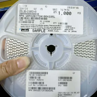
GRM155R71C104KA88D - 0.1uF 16V X7R 0402 MLCC | Murata
MPN: GRM155R71C104KA88D ✓ Active| Qty | Unit Price | Extended |
|---|---|---|
| 1 | $0.01 | $0.01 |
| 10 | $0.008 | $0.08 |
| 100 | $0.006 | $0.60 |
| 500 | $0.005 | $2.50 |
| 1,000 | $0.0042 | $4.20 |
GRM155R71C104KA88D Overview
An MLCC is a passive capacitor formed by interleaving layers of ceramic dielectric and metal electrodes, terminated at opposite ends for surface mounting. Within the component hierarchy, it belongs to the ceramic capacitor family under the broader capacitor category of passive components, and it serves as the workhorse decoupling and bypass element in modern electronics. Because MLCCs are non-polarized, they require no orientation on the PCB, simplifying assembly and enabling use in AC-coupled paths.
Key features of this part include the X7R dielectric, which holds capacitance within +/-15% across -55C to +125C, making it suitable for industrial and automotive-adjacent thermal environments. The K stepping code defines the +/-10% capacitance tolerance, tighter than the common +/-20% M-grade parts. The 16 VDC rating provides comfortable margin on 5 V, 3.3 V, and 1.8 V rails, and the small 1.0 x 0.5 mm footprint supports high-density layouts.
Technically, X7R is a ferroelectric barium-titanate-based dielectric: it offers far better temperature stability than Y5V/Z5U classes, at the cost of DC bias derating, meaning effective capacitance drops as applied DC voltage approaches the rated value. Designers should verify bias curves when tight capacitance budgets exist. The GRM15 series uses nickel inner electrodes with a lead-free outer termination for reflow soldering reliability.
Typical applications include decoupling of microcontrollers, FPGAs, and logic ICs, bypass filtering on power rails, AC coupling, and general-purpose filtering in portable devices, IoT modules, and industrial controls.
A key design consideration: keep at least 2:1 DC voltage margin (e.g., use this 16 V part on 8 V rails or lower) to limit X7R bias-induced capacitance loss, and follow IPC land-pattern recommendations for 0402 to minimize tombstoning during reflow.
This page adds information gain beyond the datasheet: verified distributor pricing tiers as of 2026-09-05, drop-in alternative analysis within the Murata GRM15 family, practical decoupling design notes, and an SEO/AEO-optimized FAQ for fast engineering lookup.
Drop-in alternatives for GRM155R71C104KA88D — same package, pin-to-pin compatible. Different-package parts requiring PCB rework are excluded.
Quick Comparison Tool — Select alternative parts for side-by-side comparison:
GRM155R71C104KA88W
✅ Drop-In📋 Reference alternative (not in catalog)
GRM155R71C104KA01D
✅ Drop-In ⚠️ 参数待验证📋 Reference alternative (not in catalog)
GRM155R71C104KE14D
✅ Drop-In ⚠️ 参数待验证📋 Reference alternative (not in catalog)
GRM155R60J104ME19D
✅ Drop-In ⚠️ 参数待验证📋 Reference alternative (not in catalog)
GRM155R71C104KA88D Maximum Ratings & Electrical Characteristics
| Capacitance | 0.1 uF (100 nF) |
| Tolerance | +/-10% (K) |
| Rated Voltage | 16 VDC |
| Dielectric | X7R (Class 2) |
| Temperature Characteristics | +/-15% from -55C to +125C |
| Case Size (Metric) | 1005 (1.0 x 0.5 mm) |
| Case Size (Imperial) | 0402 |
| Mounting Type | Surface Mount (SMD/SMT) |
| Polarization | Non-polarized |
| Termination | Nickel barrier / lead-free outer termination |
| Operating Temperature | -55C to +125C |
| Applications | General purpose, decoupling, bypass |
| RoHS Status | Compliant |
| Lead Free | Yes |
| Series | GRM15 |
| Packaging Code (D) | Paper taping, 7-inch reel variant per Murata packaging system |
GRM155R71C104KA88D 0402 Pin Configuration Guide
Pin configuration for GRM155R71C104KA88D (0402 package). Pin numbering, functions, and connection diagrams are defined in the manufacturer datasheet. Refer to it for the exact footprint and soldering guidelines.

No detailed pinout data available for GRM155R71C104KA88D.
Refer to the datasheet for full pin configuration.
Typical Applications
GRM155R71C104KA88D is suitable for 6 applications: MCU/FPGA Power Decoupling, Portable and Wearable Devices, Industrial Control and PLC Systems, IoT Modules and Wireless Nodes, Consumer Electronics BOM Cost Optimization, Test and Measurement Instrumentation.
MCU/FPGA Power Decoupling
The GRM155R71C104KA88D is the canonical local decoupling capacitor for microcontrollers, FPGAs, and digital logic ICs. Its 0.1 uF X7R capacitance with low 0402-equivalent ESL (typically well under 1 nH including mount inductance) provides a low-impedance path for switching transients in the 10-100 MHz range, keeping rail ripple within device specs. On a 3.3 V rail the 16 V rating leaves nearly 5x headroom, so DC-bias capacitance loss stays modest, preserving close to the nominal 100 nF in-circuit. Place one capacitor within 2-3 mm of each VDD pin with short, wide traces or direct via-to-plane connections; pair with a bulk 10 uF capacitor per power domain. For dense FPGA banks, the compact 1.0 x 0.5 mm footprint allows one decoupling capacitor per pin row without crowding.
Recommended
Portable and Wearable Devices
In smartphones, wearables, and compact IoT devices, board area is the scarcest resource, and the GRM155R71C104KA88D's 1005 metric (0402) case - just 1.0 x 0.5 mm with a sub-0.55 mm profile - enables very high component density. The non-polarized MLCC requires no orientation, simplifying automated optical inspection and reflow assembly compared to tantalum or electrolytic alternatives. Its X7R dielectric tolerates the -20C to +70C ambient range of body-worn electronics with only +/-15% capacitance drift across its full -55C to +125C window. On battery rails from 3.0-4.4 V (single-cell Li-ion), the 16 V rating provides generous margin, keeping bias-induced capacitance loss low for RF module bypass and codec decoupling. Typical usage is 30-100 pieces per wearable BOM, so the sub-half-cent price at 1000-piece quantities matters directly to BOM cost.
Recommended
Industrial Control and PLC Systems
Industrial controllers operate from -40C to +85C or beyond, and the GRM155R71C104KA88D's X7R specification (-55C to +125C with +/-15% capacitance change) comfortably covers these environments, unlike X5R parts limited to +85C. On 24 V-derived internal 5 V rails, the 16 VDC rating gives a 3x voltage margin that accommodates industrial supply transients. MLCC ceramic construction eliminates dry-out and wear-out mechanisms of aluminum electrolytics, supporting the 10-20 year service life expected in PLC I/O modules, motor drive control boards, and sensor transmitters. Use it for decoupling isolation amplifiers, ADC front ends, and communication transceivers; on the 24 V bus itself step up to a higher-voltage rated series, since 16 V is insufficient directly across 24 V rails.
Recommended
IoT Modules and Wireless Nodes
Wireless modules (Wi-Fi, BLE, LoRa, Zigbee) exhibit bursty transmit current drawn in microsecond pulses; the GRM155R71C104KA88D placed at each module supply pin supplies these fast transients that the bulk supply cannot. Low equivalent series inductance of the 0402 termination minimizes the impedance peak region above 10 MHz where RF PA and VCO circuitry is most sensitive, protecting phase noise and EMI performance. The 100 nF value pairs with a 1 uF and 10 uF companion to create a decade-spread decoupling network. At 3.3 V operation on this 16 V part, bias derating is small, so the effective capacitance stays near 100 nF where it matters. Sub-millimeter size also fits inside castellated-edge module footprints and shield-can perimeters where 0603/0805 parts would not.
Recommended
Consumer Electronics BOM Cost Optimization
In high-volume consumer goods - set-top boxes, appliances, LED drivers, toys, chargers - the GRM155R71C104KA88D at roughly $0.004/unit at 1000 pieces (as of 2026-09-05) is among the cheapest qualified-name-brand decoupling options available. Murata's manufacturing scale and multi-source distributor coverage (DigiKey, Mouser, LCSC, Octopart lists 11 distributors) dramatically reduce allocation risk compared to boutique brands, which matters when a consumer product ships millions of units per year. The +/-10% K tolerance (rather than +/-20% M) gives design margin on analog bias points without price premium at this class. Use it across HDMI/USB port ESD-protection networks, audio path AC coupling into high-impedance loads, and general rail bypass, standardizing one 0.1 uF MPN across the entire BOM to gain purchasing leverage.
Recommended
Test and Measurement Instrumentation
Bench instruments, data-acquisition cards, and sensor front ends demand quiet analog rails; the GRM155R71C104KA88D contributes via stable X7R behavior with no piezo-relevant large-signal excitation in bypass service, minimal ESR variation, and reliable -55C to +125C operation during calibration thermal cycling. For precision ADC reference decoupling, its 100 nF with low inductance shunts wideband noise at the REF pin; pair with a 10 uF X7R sibling for a two-capacitor network. MLCC ceramic insulation resistance is very high (typically thousands of megohms at 25C), so leakage errors in sample-hold and integrator circuits are negligible compared to tantalum. Because instruments are serviced for a decade+, Murata's long product-lifecycle commitment on the GRM15 series (active status as of 2026) protects the design against obsolescence.
Recommended
Recommended Products Summary
Engineering reference data for GRM155R71C104KA88D — comparison, design guidance, and compliance information.
Selection Guide
Comparison with Alternatives
| Parameter | This Product | GRM155R71C104KA88W | GRM155R71C104KA01D | GRM155R71C104KE14D | GRM155R60J104ME19D |
|---|---|---|---|---|---|
| Package | 0402 (1005 Metric) | 0402 (1005 Metric) - same | 0402 (1005 Metric) - same | 0402 (1005 Metric) - same | 0402 (1005 Metric) - same |
| Brand | Murata Manufacturing | Murata Manufacturing | Murata Manufacturing | Murata Manufacturing | Murata Manufacturing |
| Capacitance | 0.1 uF | 0.1 uF | 0.1 uF | 0.1 uF | 0.1 uF |
| Rated Voltage | 16 VDC | 16 VDC | 16 VDC | 16 VDC | 6.3 VDC |
| Tolerance | +/-10% (K) | +/-10% (K) | +/-10% (K) | +/-10% (K) | +/-20% (M) |
| Dielectric / Temperature Range | X7R, -55C to +125C | X7R, -55C to +125C | X7R, -55C to +125C | X7R, -55C to +125C | X5R, -55C to +85C |
| Packaging Code | D (paper taping) | W (alternate taping) | 01 (alternate taping) | E14 (alternate taping) | E19 (paper taping) |
| Drop-in Suitability | Reference part | 100% - electrically identical | 100% - electrically identical | 100% - electrically identical | 70% - verify voltage/tolerance margin first |
Key Differentiators
- Tight +/-10% K tolerance at commodity price (vs GRM155R60J104ME19D)
- X7R industrial temperature range (vs X5R-class 0402 equivalents)
- Murata manufacturing scale and multi-distributor availability (vs generic unbranded 0402 MLCCs)
Design Notes
For the 0402 (1005 metric) land pattern, follow IPC-recommended dimensions of approximately 0.5-0.6 mm pads with ~0.5 mm pad-to-pad spacing. To minimize tombstoning during reflow, keep the two pads thermally symmetric - equal copper connection widths - and avoid connecting one pad directly to a large plane without thermal relief. With 1.0 x 0.5 mm bodies, paste apertures at 90-100% of pad size typically give reliable transfer efficiency on standard 0.1 mm stencil foil.
X7R capacitance derates under DC bias and ages over time (approximately 1-3% per decade-hour). Do not assume the full 0.1 uF is present at operating voltage; on this 16 V part, bias at 3.3-5 V retains most capacitance, but biasing near 12-16 V can cut effective capacitance substantially. Also never use this 16 V part directly across 24 V industrial rails - select Murata's 50 V-rated GRM series siblings for that node. Estimated: at 5 V bias (31% of rating), expect roughly 10-20% capacitance loss per typical X7R bias curves.
For decoupling service, route each 0.1 uF capacitor with via-in-pad or via-at-pad connections to the power and ground planes, keeping the total loop length under 2 mm. Place the smallest capacitor (this 0402) closest to the IC power pin, with larger bulk capacitors (1 uF, 10 uF) farther away. Daisy-chaining multiple ICs to one shared 0.1 uF capacitor is a common mistake - allocate one capacitor per power/ground pin pair per the IC vendor's power-supply design guidance.
Compliance Information
RoHS compliant and lead-free per Murata GRM series construction (nickel-barrier lead-free termination) and DigiKey/Mouser listings. Some Murata termination materials reference trace Pb under JEDEC JESD97 per TTI data - confirm on the specific datasheet page if absolute Pb-free termination certification is required. AEC-Q100 not applicable to passive capacitors (refer to AEC-Q200 qualification if automotive MLCC screening is needed; not stated in provided data).