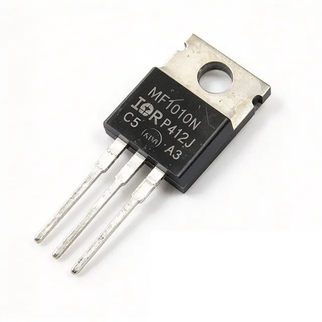
IRF1010NPBF - 55V 85A N-Channel Power MOSFET | Infineon
MPN: IRF1010NPBF ✓ Active| Qty | Unit Price | Extended |
|---|---|---|
| 1 | $2.45 | $2.45 |
| 10 | $2.21 | $22.10 |
| 100 | $1.86 | $186.00 |
| 500 | $1.58 | $790.00 |
| 1,000 | $1.32 | $1,320.00 |
IRF1010NPBF Overview
A power MOSFET is a voltage-controlled semiconductor switch used to regulate or switch high currents in power management systems. Within the component hierarchy, it sits under transistor > field-effect transistor (FET) > MOSFET > power MOSFET, and it forms the switching element of power supplies, motor drives, and DC-DC converters. The IRF1010NPBF belongs to Infineon (formerly International Rectifier) HEXFET family, one of the most widely second-sourced power MOSFET platforms in the industry.
Key features include a 55 V drain-to-source breakdown voltage, 11 mOhm maximum on-resistance at 10 V gate drive, and approximately 80 nC total gate charge for efficient gate-drive design. The planar cell structure provides a wide safe operating area (SOA), and the device is qualified according to JEDEC standards for the industrial market, per the manufacturer datasheet.
The advanced process technology achieves extremely low on-resistance per unit silicon area, combining fast switching with a ruggedized device design. Infineon positions this generation of planar MOSFETs for applications switching below 100 kHz, where the planar structure delivers robust avalanche and dv/dt capability that newer trench devices may not match.
Typical applications include DC motor control and H-bridge legs, switching power supplies and DC-DC converters, high-current UPS and inverter stages, and battery-powered industrial equipment. The through-hole TO-220AB package simplifies prototyping, heatsink attachment, and high-power thermal design.
A key design consideration: at high currents, conduction losses dominate (I^2 x Rds(on)); at 85 A the device dissipates roughly 70 W as an estimate (85A squared times 0.011 Ohm), so a substantial heatsink and low-thermal-resistance mounting are mandatory. Optimize gate drive at 10 V to guarantee the specified Rds(on).
This page synthesizes distributor pricing, drop-in alternatives, pinout, comparison tables, and practical design notes not found in the manufacturer datasheet.
Drop-in alternatives for IRF1010NPBF — same package, pin-to-pin compatible. Different-package parts requiring PCB rework are excluded.
Variants in this series
Same-series models that are drop-in compatible with IRF1010NPBF (same form factor and footprint) — differing in Configuration, Market Qualification, Package, RoHS Status.
Quick Comparison Tool — Select alternative parts for side-by-side comparison:
IRF1010EPBF
✓ In Stock
$0.45 / Unit
View Datasheet →IRF3205PBF
📋 Reference alternative (not in catalog)
IRFI1010NPBF
📋 Reference alternative (not in catalog)
IRFB3006PBF
📋 Reference alternative (not in catalog)
IRFB3206PBF
📋 Reference alternative (not in catalog)
IRF1010NPBF Maximum Ratings & Electrical Characteristics
| FET Type | N-Channel MOSFET |
| Technology | HEXFET planar |
| Drain-to-Source Voltage (Vdss) | 55 V |
| Continuous Drain Current (Id) at Tc | 85 A |
| Drain-Source On-Resistance (Rds(on)) | 11 mOhm max at 10 V gate drive |
| Total Gate Charge (Qg) | 80 nC |
| Power Dissipation (Pd) | 180 W (Tc) |
| Package | TO-220AB |
| Mounting Type | Through Hole |
| Configuration | Single FET, 1 element |
| Polarity | N-Channel |
| Series | HEXFET |
| Recommended Switching Frequency | Below 100 kHz |
| Market Qualification | Industrial (JEDEC per manufacturer) |
| RoHS Status | Compliant (PbF = lead-free) |
IRF1010NPBF Pin Configuration
| Pin 1 | Gate — Gate control terminal; drive 10 V for specified Rds(on) |
| Pin 2 | Drain — Drain terminal; also connected to metal mounting tab |
| Pin 3 | Source — Source terminal; reference for gate drive |
Safe Operating Area (TO-220AB, Tc = 25C)
Typical Applications
IRF1010NPBF is suitable for 6 applications: DC Motor Control, Switch-Mode Power Supplies, UPS and Inverter Stages, Battery-Powered Industrial Equipment, Automotive and Heavy-Load Relay Replacement, Prototyping and Repair of Power Boards.
DC Motor Control
The IRF1010NPBF fits DC motor drive half-bridges and H-bridge legs because its 55 V rating covers 12 V and 24 V motor buses with generous transient margin, while the 11 mOhm on-resistance limits conduction loss to about 6 W at 25 A continuous (estimated: 25A squared times 0.011 Ohm). In an H-bridge, two low-side devices handle PWM chopping and two high-side devices handle direction reversal; the planar cell structure of the IRF1010N tolerates the avalanche energy and dv/dt stress that inductive motor loads generate during commutation. Drive the gate at 10 V with a low-impedance driver to guarantee the specified Rds(on), and size the heatsink from the datasheet thermal resistance for worst-case locked-rotor current.
Recommended
Switch-Mode Power Supplies
In switch-mode power supplies and DC-DC converters below 100 kHz, the IRF1010NPBF serves as the primary-side switch or synchronous rectifier. Infineon specifically optimizes this planar generation for switching below 100 kHz, where its approximately 80 nC gate charge keeps drive losses modest and the ruggedized body-diode and SOA behavior handle transformer leakage spikes. In a forward or push-pull converter from a 24 V or 48 V input rail, the 55 V breakdown provides adequate derating when clamped by an RCD snubber. Note the trade-off: switching loss rises with frequency, so above 100 kHz a trench MOSFET with lower gate charge is the better fit.
Recommended
UPS and Inverter Stages
Uninterruptible power supplies and low-frequency inverters use the IRF1010NPBF in high-current push-pull and full-bridge stages switching the battery bus into a 50/60 Hz transformer. The 85 A continuous rating at Tc and 180 W dissipation capability support stacked paralleling for kilowatt-class outputs, and the planar structure's wide SOA withstands transformer inrush and short-circuit transients better than narrow-SOA trench parts. At 12 V or 24 V battery bus voltages, the 55 V rating leaves ample avalanche margin against load-dump-like spikes. Use a 10 V gate drive, kelvin-source connections for paralleled devices, and individual gate resistors to suppress parasitic oscillation between paralleled MOSFETs.
Recommended
Battery-Powered Industrial Equipment
Battery-operated industrial equipment such as floor machines, material-handling carts, and portable welders switch tens of amperes from 12 V to 48 V packs, and the IRF1010NPBF addresses this with 55 V breakdown, 11 mOhm on-resistance, and through-hole TO-220AB mounting that survives vibration better than fine-pitch SMD when mechanically retained. Conduction loss at 30 A is approximately 9.9 W (estimated: 30A squared times 0.011 Ohm), which a modest forced-air or finned heatsink can manage. The industrial-market qualification cited in the Infineon datasheet and the JEDEC-based product qualification support use in ruggedized equipment. Guard against deep battery discharge transients exceeding the 55 V rating with a TVS clamp.
Recommended
Automotive and Heavy-Load Relay Replacement
The IRF1010NPBF replaces electromechanical relays and contactors in 12 V and 24 V systems such as winch controllers, heater element switches, and solenoid drivers. Unlike a relay, the MOSFET offers millions of switching cycles with no contact arcing: its 55 V, 85 A envelope covers starter-class loads, and 11 mOhm on-resistance dissipates only about 11 W at 32 A (estimated: 32A squared times 0.011 Ohm), less than cable losses in many installations. The TO-220AB tab allows bolting to a chassis heat path. Because the tab is at drain potential, isolate it electrically when the chassis is grounded, or choose the IRFI1010N Full-Pak variant for inherently isolated mounting.
Recommended
Prototyping and Repair of Power Boards
The through-hole TO-220AB package makes the IRF1010NPBF a staple for breadboarding power stages and repairing legacy power boards. The industry-standard gate-drain-source pinout matches countless IR-family footprints, so it swaps directly into IRF3205, IRF1010E, and similar TO-220AB positions after verifying voltage and current ratings. Its planar process is forgiving of hand-soldering heat and slow gate edges during bench testing, and the wide SOA tolerates the unclamped inductive loads common on a prototype bench. Always verify the original part's Vgs drive level: substituting into a 5 V-drive circuit yields higher Rds(on) than the 11 mOhm specification, which assumes 10 V gate drive.
Recommended
Recommended Products Summary
Engineering reference data for IRF1010NPBF — comparison, design guidance, and compliance information.
Selection Guide
Comparison with Alternatives
| Parameter | This Product | IRF3205PBF | IRFI1010NPBF | IRF1010EPBF | IRFB3006PBF | IRFB3206PBF |
|---|---|---|---|---|---|---|
| Package | TO-220AB | TO-220AB - same | TO-220 Full-Pak (isolated body, same lead pattern) | TO-220AB - same | TO-220AB - same | TO-220AB - same |
| Brand | Infineon | Infineon | Infineon | Infineon | Infineon | Infineon |
| Vdss | 55 V | 55 V | 55 V | 55 V | 60 V | 60 V |
| Isolation (tab vs drain) | Not isolated (drain on tab) | Not isolated | Electrically isolated (Full-Pak) | Not isolated | Not isolated | Not isolated |
| Technology | HEXFET planar | HEXFET | HEXFET planar (same die) | HEXFET (earlier generation) | HEXFET | HEXFET |
Key Differentiators
- Wide SOA from planar cell structure (vs IRF3205PBF)
- Isolated mounting option in same family (vs IRFI1010NPBF)
- Cost-effective at moderate current (vs IRFB3006PBF)
Design Notes
The 180 W rating assumes the TO-220AB tab is held at 25C, which no free-air mounting achieves. Estimated example: at 40 A with 11 mOhm Rds(on), conduction dissipation is about 17.6 W; with a junction-to-case resistance of roughly 1 C/W-class and a realistic heatsink stack, plan for 20 C/W or better total thermal resistance to keep junction temperature below 125C at 40C ambient. Use a mica or silicone pad with thermal grease (or the isolated IRFI1010N Full-Pak) when the grounded heatsink cannot sit at drain potential.
The 11 mOhm Rds(on) specification is guaranteed at 10 V gate-source voltage. Designs driving the gate at 4.5 V or 5 V (logic-level style) will see significantly higher on-resistance and conduction loss; the IRF1010N is not a logic-level MOSFET. Use a dedicated gate driver (e.g., IR2110-class) with a low-impedance output and a 10 V to 12 V gate rail, and place a 10-20 Ohm gate resistor close to the gate pin to dampen ringing. Verify the SOA curves for unclamped inductive switching margins per the Infineon datasheet.
Do not exceed the 55 V drain-source rating: automotive load-dump and motor-regeneration events routinely exceed it without clamping. Add a TVS diode or snubber across the drain-source node in inductive applications. In paralleled configurations, the planar structure's positive temperature coefficient of Rds(on) aids current sharing, but still use individual gate resistors and a tight kelvin-source layout to prevent parasitic oscillation. Finally, remember the tab is electrically drain - a grounded heatsink creates a short circuit unless isolated.
Keep the gate drive loop small: route the driver output to pin 1 with a short trace, and place the gate pull-down resistor directly at the pin. For through-hole designs, minimize the source-return loop area between pin 3 and the driver ground to reduce stray inductance-induced gate spikes during fast switching. On double-sided boards, use copper pour for the drain tab connection to spread heat into the PCB as a supplementary conduction path.
Compliance Information
PbF suffix denotes lead-free/RoHS-compliant version per Infineon. Product qualified for industrial market per JEDEC standards per datasheet. REACH, halogen-free and conflict-minerals declarations not stated in provided data - obtain current certificate from Infineon.

