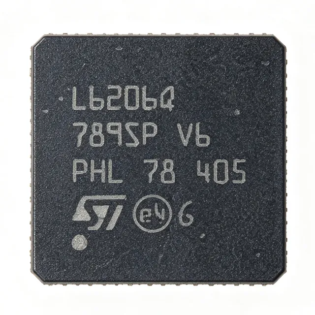
L6206Q - Dual DMOS Full-Bridge Driver 8A | STMicroelectronics
MPN: L6206Q ✓ Active| Qty | Unit Price | Extended |
|---|---|---|
| 1 | $1.2 | $1.20 |
| 10 | $1.12 | $11.20 |
| 100 | $0.99 | $99.00 |
| 500 | $0.96 | $480.00 |
| 1,000 | $0.93 | $930.00 |
| 2,500 | $0.89 | $2,225.00 |
L6206Q Overview
A DMOS full-bridge driver is a type of power integrated circuit that uses four N-channel DMOS transistors arranged in an H-bridge configuration to control the direction and speed of a DC motor or the phase currents of a stepper motor. It belongs to the broader category of motor drivers, which are power management ICs that translate low-power control signals into high-current, high-voltage outputs. The L6206Q sits in the hierarchy: DMOS full-bridge driver -> motor driver -> power management IC -> semiconductor.
Key features include a low RDS(on) of 0.3 ohm per switch, which minimizes power dissipation and improves efficiency, and a fast switching frequency of up to 100 kHz, enabling precise PWM control. The device also features a non-dissipative overcurrent protection (OCP) that limits the output current to a safe level, and a diagnostic output that indicates fault conditions. The QFN48 package provides a compact footprint with an exposed thermal pad for enhanced heat dissipation.
The L6206Q uses a mixed-signal BCD (Bipolar-CMOS-DMOS) process technology, integrating the DMOS power stage with CMOS control logic and bipolar protection circuits. This architecture allows for high current handling with low quiescent current and robust protection features. The device supports both parallel and bridge configurations, enabling flexible motor drive topologies.
Typical applications include bipolar stepper motor drivers, DC motor drivers for robotics and automation, and brushless DC motor pre-drivers. The wide supply voltage range and high current capability make it ideal for industrial automation, CNC machines, and automotive actuators. In a stepper motor application, the L6206Q can drive two-phase motors with up to 2.8A per phase, providing smooth microstepping control.
When designing with this device, ensure adequate PCB copper area for the thermal pad to dissipate heat, especially at high output currents. The VREF pin allows current sensing and regulation, which is essential for torque control in stepper applications. The EN pins provide independent enable control for each bridge, enabling power-saving modes.
This page synthesizes distributor pricing, drop-in alternatives, and practical design notes not found in the ST datasheet, providing a comprehensive resource for engineers selecting a dual full-bridge driver.
Drop-in alternatives for L6206Q — same package, pin-to-pin compatible. Different-package parts requiring PCB rework are excluded.
Quick Comparison Tool — Select alternative parts for side-by-side comparison:
L6206PD
📋 Reference alternative (not in catalog)
L6206QTR
📋 Reference alternative (not in catalog)
L6206PD013TR
📋 Reference alternative (not in catalog)
L6206Q Maximum Ratings & Electrical Characteristics
| Supply Voltage Range | 8 V to 52 V |
| Output Current per Channel | 2.8 A |
| Total Output Current | 5.6 A |
| Peak Output Current | 8 A |
| RDS(on) per Switch | 0.3 ohm |
| Switching Frequency | 100 kHz (max) |
| Number of Bridges | 2 |
| Output Type | Dual Full-Bridge |
| Protection Features | Thermal Shutdown, Undervoltage Lockout, Overcurrent Protection |
| Package | QFN48 (7x7 mm) |
| Mounting Type | Surface Mount |
| Operating Temperature | -40C to +150C |
| RoHS Status | Compliant |
| Logic Input Voltage | 5 V (TTL compatible) |
L6206Q Pin Configuration
| Pin 1 | OUT1A — Output of bridge 1, channel A |
| Pin 2 | OUT1B — Output of bridge 1, channel B |
| Pin 3 | VS — Power supply voltage |
| Pin 4 | OUT2A — Output of bridge 2, channel A |
| Pin 5 | OUT2B — Output of bridge 2, channel B |
| Pin 6 | GND — Ground |
| Pin 7 | IN1A — Logic input for bridge 1, channel A |
| Pin 8 | IN1B — Logic input for bridge 1, channel B |
| Pin 9 | IN2A — Logic input for bridge 2, channel A |
| Pin 10 | IN2B — Logic input for bridge 2, channel B |
| Pin 11 | EN1 — Enable for bridge 1 |
| Pin 12 | EN2 — Enable for bridge 2 |
| Pin 13 | VREF1 — Current sense reference for bridge 1 |
| Pin 14 | VREF2 — Current sense reference for bridge 2 |
| Pin 15 | DIAG1 — Diagnostic output for bridge 1 |
| Pin 16 | DIAG2 — Diagnostic output for bridge 2 |
Typical Applications
L6206Q is suitable for 6 applications: Bipolar Stepper Motor Driver, DC Motor Driver for Robotics, Brushless DC Motor Pre-Driver, Industrial Automation Actuator, Automotive Actuator Control, CNC Machine Axis Driver.
Bipolar Stepper Motor Driver
The L6206Q is ideal for driving bipolar stepper motors in applications such as 3D printers, CNC machines, and robotics. Its dual full-bridge configuration allows direct control of the two motor phases, with each bridge capable of delivering up to 2.8A. The fast switching frequency of up to 100kHz enables microstepping, which improves motion smoothness and positional accuracy. In a typical stepper driver circuit, the L6206Q is connected to a microcontroller via the logic inputs, with current sensing resistors on the VREF pins to regulate phase current. The device's low RDS(on) of 0.3 ohm minimizes power loss, allowing efficient operation at high currents. Thermal performance is critical in this application; the QFN48 package's exposed pad must be soldered to a large copper area to dissipate heat generated during continuous operation. The integrated overcurrent protection prevents damage from motor stalls or wiring faults, making the L6206Q a robust choice for industrial and hobbyist stepper applications.
Recommended
DC Motor Driver for Robotics
The L6206Q can drive two DC motors independently, making it suitable for differential-drive robots, conveyor systems, and automated guided vehicles. Each bridge can supply up to 2.8A, sufficient for small to medium DC motors. The wide supply voltage range of 8V to 52V allows operation from various battery packs or industrial power supplies. In a robot, the L6206Q is typically controlled by PWM signals from a microcontroller to regulate motor speed and direction. The device's fast switching frequency reduces audible noise and improves efficiency. The integrated protection features, including thermal shutdown and overcurrent protection, enhance system reliability. For high-current motors, proper PCB layout with adequate copper for the thermal pad is essential to prevent overheating. The L6206Q's compact QFN48 package saves board space, enabling dense robot designs.
Recommended
Brushless DC Motor Pre-Driver
The L6206Q can be used as a pre-driver for brushless DC (BLDC) motors, where it drives the power stage that controls the motor windings. In this application, the L6206Q's two full-bridges can be configured to drive the three phases of a BLDC motor in a trapezoidal or sinusoidal commutation scheme. The high switching frequency of up to 100kHz supports advanced commutation algorithms, reducing torque ripple and improving efficiency. The device's low RDS(on) minimizes power loss in the drive stage. The L6206Q's logic inputs are compatible with 5V microcontrollers, simplifying the interface. For BLDC applications, the L6206Q is often paired with a Hall sensor or encoder feedback for rotor position sensing. The integrated protection features ensure safe operation under fault conditions, such as overcurrent or over-temperature.
Recommended
Industrial Automation Actuator
The L6206Q is well-suited for driving actuators in industrial automation, such as linear actuators, valve controls, and conveyor systems. Its robust design, with a supply voltage range up to 52V and output current up to 2.8A per channel, can handle the demands of industrial environments. The device's protection features, including thermal shutdown and overcurrent protection, ensure reliable operation in harsh conditions. In an actuator application, the L6206Q is typically controlled by a PLC or industrial microcontroller, with PWM signals for speed control. The wide operating temperature range of -40C to +150C allows operation in unheated factory floors or outdoor installations. The QFN48 package's thermal pad must be properly connected to a heatsink or large copper area to manage heat dissipation during continuous operation. The L6206Q's dual-bridge configuration also allows for redundant or multi-axis control in a single package.
Recommended
Automotive Actuator Control
The L6206Q can be used in automotive applications such as power window motors, seat adjusters, and mirror actuators. Its wide supply voltage range (8V to 52V) accommodates the 12V and 24V automotive electrical systems, and its high current capability drives the motors directly. The device's operating temperature range of -40C to +150C meets automotive requirements. Although not explicitly AEC-Q100 qualified, the L6206Q's robust design and protection features make it suitable for many automotive applications. In a power window system, the L6206Q is controlled by a body control module (BCM) via PWM signals, with current sensing for anti-pinch detection. The integrated overcurrent protection prevents damage during motor stall conditions. For automotive designs, additional EMC filtering may be required to meet CISPR 25 standards. The compact QFN48 package helps reduce the size of electronic control units (ECUs).
Recommended
CNC Machine Axis Driver
The L6206Q is suitable for driving the axis motors of CNC machines, where precise position and speed control are essential. Its dual full-bridge configuration can drive two stepper or DC motors, enabling multi-axis control with a single IC. The high switching frequency of up to 100kHz supports microstepping, which improves surface finish and positional accuracy. In a CNC controller, the L6206Q is typically interfaced with a motion control IC or FPGA that generates step and direction signals. The device's low RDS(on) minimizes heat generation, allowing continuous operation at high currents. The integrated protection features, including overcurrent and thermal shutdown, protect the motors and the driver from faults. For high-performance CNC applications, proper thermal management is critical; the QFN48 package's exposed pad should be connected to a heatsink or large copper area. The L6206Q's wide supply voltage range allows operation from various power supplies, from 12V to 48V.
Recommended
Recommended Products Summary
Engineering reference data for L6206Q — comparison, design guidance, and compliance information.
Selection Guide
Comparison with Alternatives
| Parameter | This Product | L6206PD | L6206QTR | L6206PD013TR |
|---|---|---|---|---|
| Package | QFN48 (7x7 mm) | QFN48 (7x7 mm) - same | QFN48 (7x7 mm) - same | QFN48 (7x7 mm) - same |
| Supply Voltage Range | 8V to 52V | 8V to 52V | 8V to 52V | 8V to 52V |
| Output Current per Channel | 2.8A | 2.8A | 2.8A | 2.8A |
| RDS(on) | 0.3 ohm | 0.3 ohm | 0.3 ohm | 0.3 ohm |
| Switching Frequency | 100 kHz | 100 kHz | 100 kHz | 100 kHz |
| Protection Features | Thermal Shutdown, UVLO, OCP | Thermal Shutdown, UVLO, OCP | Thermal Shutdown, UVLO, OCP | Thermal Shutdown, UVLO, OCP |
| Operating Temperature | -40C to +150C | -40C to +150C | -40C to +150C | -40C to +150C |
| Packaging | Tray | Tape & Reel | Tape & Reel | Tape & Reel |
Key Differentiators
- High output current capability (vs L298N)
- Low RDS(on) for higher efficiency (vs L298N)
- Compact QFN48 package (vs L6206 (DIP-20))
Design Notes
The L6206Q in QFN48 package has an exposed thermal pad that must be soldered to a large copper area on the PCB to dissipate heat. At maximum output current of 2.8A per channel, power dissipation can be significant. For example, with RDS(on) of 0.3 ohm, each switch dissipates I^2*R = 2.8^2 * 0.3 = 2.35W, and with two switches conducting per bridge, total dissipation per bridge is 4.7W. Ensure the PCB has adequate thermal vias and copper pour to keep the junction temperature below 150C.
Place the L6206Q close to the motor connectors to minimize trace inductance and resistance. Use wide, short traces for the output pins (OUT1A, OUT1B, OUT2A, OUT2B) to handle high currents. Decouple the VS pin with a 100nF ceramic capacitor and a 10uF electrolytic capacitor placed as close as possible to the IC. The VREF pins should have a sense resistor to ground for current regulation, with the sense resistor placed near the IC to avoid noise pickup.
Do not exceed the absolute maximum supply voltage of 52V. Ensure the logic inputs are not driven above the logic supply voltage. The EN pins must be properly pulled high or low to avoid undefined states. When using the overcurrent protection, note that it is non-dissipative and will limit the output current; do not rely on it for continuous operation. Always provide a freewheeling path for inductive loads, such as flyback diodes, to prevent voltage spikes from damaging the device.
Compliance Information
RoHS compliant per STMicroelectronics product page. Not AEC-Q100 qualified. Lead-free.






