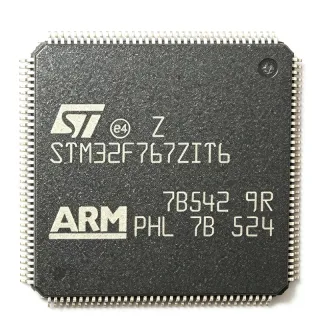
S912XDP512J1CAG - 16-bit S12X MCU, 512KB Flash, 80MHz, 144-LQFP
MPN: S912XDP512J1CAG ⚠ Last Time Buy| Qty | Unit Price | Extended |
|---|---|---|
| 1 | $22.5 | $22.50 |
| 10 | $20.25 | $202.50 |
| 100 | $18.1 | $1,810.00 |
| 500 | $16.45 | $8,225.00 |
| 1,000 | $14.85 | $14,850.00 |
S912XDP512J1CAG Overview
A microcontroller (MCU) is a single-chip computer that integrates a CPU, memory, and programmable peripherals onto one silicon die. The HCS12X family extends the classic HCS12 instruction set with enhanced indexed addressing, a 4-byte instruction queue, and interrupt stacking identical to HCS12, enabling upward code compatibility. Within NXP's taxonomy, HCS12X sits in the 16-bit MCU tier below 32-bit PowerPC and Cortex-M devices, but above 8-bit HC08/HC(S)08 families - targeting cost-sensitive real-time control applications where deterministic interrupt latency and ample on-chip peripherals outweigh raw MHz.
Key features of the S912XDP512J1CAG include 32KB of RAM, 4KB of EEPROM, an Enhanced Capture Timer (ECT), up to 8 PWM channels, two CAN 2.0 A/B controllers, multiple SCI/UART ports, SPI and IIC interfaces, an 8-channel 10-bit or 12-bit ADC, and on-chip voltage regulator with 2.5V core. The 144-LQFP package exposes the full S12XD peripheral complement including external bus interface for expanded memory.
The S12XD architecture uses a pipelined CPU with separate program and data buses, allowing simultaneous Flash fetches and SRAM accesses - effectively doubling throughput compared to the original HCS12. The XGate peripheral coprocessor (configurable on S12XD variants) offloads interrupt-driven tasks such as CAN message handling, freeing the main CPU for control loops. The enhanced indexed addressing and instruction queue support C compilers efficiently, while retaining HC12 assembly compatibility for legacy code reuse.
Typical applications include automotive body control modules (BCM), instrument clusters, HVAC controls, body lighting, seat controllers, door modules, and industrial CAN-node controllers. The dual-CAN interface and large Flash footprint also suit CAN-based diagnostic gateways in heavy machinery, agricultural equipment, and electric vehicle auxiliary systems where AEC-Q100 grade is required.
When designing with this MCU, allocate careful PCB real-estate to the 144-LQFP footprint (20x20mm body, 0.5mm pitch) and ensure four-layer routing with adequate ground pour under the exposed pad for thermal management. The internal 2.5V voltage regulator requires decoupling on VDDX/VSSX and VDDR/VSSR pins to support stable core operation up to 80MHz.
This page synthesizes distributor pricing, drop-in alternative cross-references, and practical S12XD design notes not consolidated on any single manufacturer or distributor page, helping engineers evaluate S912XDP512J1CAG for new designs and locating qualified equivalents for ongoing production.
Drop-in alternatives for S912XDP512J1CAG — same package, pin-to-pin compatible. Different-package parts requiring PCB rework are excluded.
Variants in this series
Same-series models that are drop-in compatible with S912XDP512J1CAG (same form factor and footprint) — differing in Package, Operating Temperature, PWM Channels, ADC, ADC Resolution.
Quick Comparison Tool — Select alternative parts for side-by-side comparison:
S912XDT512MAA
✅ Drop-In📋 Reference alternative (not in catalog)
S912XDG512J1CAG
✅ Drop-In📋 Reference alternative (not in catalog)
MC9S12XDT512MAA
✅ Drop-In✓ In Stock
Contact for price
View Datasheet →MC9S12XEP768CAG
✅ Drop-In✓ In Stock
$19.85 / Unit
View Datasheet →MC9S12DT128MPVE
✅ Drop-In✓ In Stock
$36.5 / Unit
View Datasheet →S912XHZ512F1VAG
✅ Drop-In📋 Reference alternative (not in catalog)
S912XDP512J1CAG Maximum Ratings & Electrical Characteristics
| Core Architecture | HCS12X (S12XD family) |
| Data Bus Width | 16-bit |
| Program Memory (Flash) | 512 KB (512K x 8) |
| RAM Size | 32 KB |
| EEPROM Size | 4 KB |
| CPU Clock Frequency (Max) | 80 MHz |
| Operating Supply Voltage | 2.5 V |
| Operating Temperature Range | -40C to +85C |
| Package | 144-LQFP (20x20 mm, 0.5 mm pitch) |
| Mounting Type | Surface Mount |
| CAN Controllers | 2 (CAN 2.0 A/B) |
| SCI / UART | Multiple |
| SPI / IIC | Yes |
| ADC | 8-channel, 10/12-bit |
| PWM Channels | Up to 8 |
| Automotive Qualified | Yes (per NXP product page) |
| RoHS Status | Compliant |
S912XDP512J1CAG 144-lqfp (20x20 mm, 0.5 mm pitch) Pin Configuration Guide
Pin configuration for S912XDP512J1CAG (144-lqfp (20x20 mm, 0.5 mm pitch) package). This digital IC includes GPIO, communication interfaces (UART, SPI, I2C), and power pins. Refer to the manufacturer datasheet for alternate pin functions and configuration options. Essential for embedded system design and PCB layout.

No detailed pinout data available for S912XDP512J1CAG.
Refer to the datasheet for full pin configuration.
Typical Applications
S912XDP512J1CAG is suitable for 6 applications: Automotive Body Control Module (BCM), Automotive Instrument Cluster, HVAC Climate Control Module, Agricultural Equipment CAN Node, Industrial CAN-Open Motor Controller, Electric Vehicle Auxiliary Module.
Automotive Body Control Module (BCM)
The S912XDP512J1CAG fits body control modules through its dual CAN 2.0A/B controllers, 512KB Flash for CAN stack plus body firmware, and 32KB RAM for runtime data buffering. The 80MHz S12X core runs scheduling loops for window lifters, mirror adjustments, and lighting drivers in real time. Compared to a Cortex-M0+ approach, the S12X core's mature BDM debug path and AEC-qualified silicon reduce certification cost. Pair with a CAN transceiver like TJA1050 and a 5V LDO such as TPS7A4700 for a typical BCM reference design.
Recommended
Automotive Instrument Cluster
For instrument clusters the S912XDP512J1CAG's Enhanced Capture Timer (ECT) drives stepper motor gauges while SPI controls LED driver ICs for backlight and telltale indicators. Its 512KB Flash holds graphics libraries, CAN stack, and OBD-II diagnostics, and the 8-channel 10/12-bit ADC reads fuel level, temperature, and battery sense channels simultaneously. The automotive-qualified -40C/+85C window covers cabin environments. Substitute with S912XET512B-MAGR for 144-MAPBGA if space-constrained PCB layouts demand.
Recommended
HVAC Climate Control Module
In HVAC control units, the S912XDP512J1CAG's up to 8 PWM channels drive blower motors, mode door actuators, and blend door steppers, while SCI interfaces communicate with the climate panel. Its dual CAN bus connects to vehicle CAN-FD backbone for setpoint delivery, and the on-chip temperature sensor plus external ADC inputs measure cabin and ambient air. Use NXP's CodeWarrior or Cosmic compiler with the standard BDM probe for in-circuit calibration routines.
Recommended
Agricultural Equipment CAN Node
Heavy agricultural machinery uses the S912XDP512J1CAG as a sealed CAN node controller. The S12XD core handles ISOBUS J1939 messaging, while SCI interfaces talk to legacy RS-485 implements, and the 512KB Flash stores implement profile tables and diagnostics logs. The industrial -40C/+85C range survives tractor cab conditions, and the 144-LQFP package welds cleanly onto conformal-coated heavy-equipment PCBs. Pair with a robust ISO 7637-2 transient-protected supply.
Recommended
Industrial CAN-Open Motor Controller
The S912XDP512J1CAG serves CAN-Open distributed motor drives where determinism and CAN bus reliability drive the design. The S12XD's enhanced indexed addressing and 4-byte instruction queue execute motion profiles efficiently, while its 32KB RAM holds trajectory planner state without overflow. Two independent CAN channels separate drive-to-drive coordination from host supervisory commands. Use the PWM outputs paired with a gate driver like IR2110 for low-voltage BLDC stages.
Recommended
Electric Vehicle Auxiliary Module
For EV auxiliary modules such as battery management slaves, the S912XDP512J1CAG's 512KB Flash holds cell-balancing algorithms, SPI battery monitor interface, and dual CAN channels for redundancy required by ISO 26262 ASIL-rated systems. Eight ADC channels monitor cell voltages and temperatures through external muxes while PWM channels drive balancing MOSFETs. The AEC-Q100 qualified silicon and -40C/+85C range match typical EV pack environments.
Recommended
Recommended Products Summary
Engineering reference data for S912XDP512J1CAG — comparison, design guidance, and compliance information.
Selection Guide
Comparison with Alternatives
| Parameter | This Product | S912XDT512MAA | S912XDG512J1CAG | MC9S12XDT512MAA | MC9S12XEP768CAG | MC9S12DT128MPVE | S912XHZ512F1VAG |
|---|---|---|---|---|---|---|---|
| Brand | NXP Semiconductors | NXP Semiconductors | NXP Semiconductors | NXP Semiconductors (legacy Freescale) | NXP Semiconductors | NXP Semiconductors | NXP Semiconductors |
| Package | 144-LQFP | 144-LQFP - same | 144-LQFP - same | 144-LQFP - same | 144-LQFP - same | 144-LQFP - same | 144-LQFP - same |
| Core | HCS12X (S12XD) | HCS12X (S12XD) | HCS12X (S12XD) | HCS12X (S12XD) | HCS12X (S12XEP) | HCS12X | HCS12X |
| Flash Memory | 512 KB | 512 KB | 512 KB | 512 KB | 768 KB | 128 KB | 512 KB |
| CPU Clock (Max) | 80 MHz | 80 MHz | 80 MHz | 80 MHz | 80 MHz | 25 MHz | 80 MHz |
| Operating Temperature | -40C to +85C | -40C to +85C | -40C to +85C | -40C to +85C | -40C to +85C | -40C to +85C | -40C to +85C |
| CAN Controllers | 2 | 2 | 2 | 2 | 5 | 2 | 2 |
| Automotive Qualified | Yes | Yes | Yes | Yes | Yes | Yes | Yes |
| RoHS Status | Compliant | Compliant | Compliant | Compliant | Compliant | Compliant | Compliant |
Key Differentiators
- Largest Flash in last-time-buy S12XD automotive tier (vs MC9S12DT128MPVE)
- Five-CAN scalability within same package (vs MC9S12XEP768CAG)
- Dual-identical S12XD members enable safe dual-sourcing (vs S912XHZ512F1VAG)
Design Notes
The 144-LQFP-20x20 with 0.5mm pitch demands 4-layer PCB stack-up with dedicated power and ground planes. Estimated: per NXP S12XD reference manual, a single via between paddle and ground pour provides ~0.3 C/W thermal improvement; recommend at least 9 thermal vias in a 3x3 pattern beneath the exposed pad. Use 0.2mm trace/space design rules and microvia-in-pad for BGA fan-out if migrating to MAPBGA variants.
Per the S12XD reference manual, the internal 2.5V voltage regulator requires 1uF ceramic decoupling on VDDX/VSSX plus 100nF on VDDPLL/VSSPLL for stable 80MHz core operation. Estimated: total quiescent current for dual CAN + ADC + ECT active = ~85mA at 5V; the MCU's internal regulator has 1A capacity. Place reverse-battery and load-dump protection (e.g., SMBJ24CA) on the supply input per ISO 7637-2 for automotive designs.
Per NXP ERRATA documents for the S12XD family, several errata affect early mask revisions: ECT channel routing during STOP mode, ADC accuracy at high temperature, and XGate coprocessor lock-up under specific CAN interrupt ordering. Always check the latest NXP S12XD errata PDF before committing to PCB layout. Use mask-set 1N95E or later to avoid documented PWM timing issues. Also, reserve BKGD pin access on the schematic for production-line BDM programming.
Compliance Information
RoHS and REACH compliance per NXP product page and DigiKey catalog listing. AEC-Q100 grade listed by NXP as automotive qualified per product page; for AEC-Q100 cross-reference document number contact NXP. Part is in last_time_buy status per the NXP product page lifecycle header.