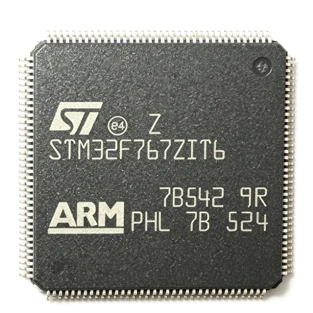
STM32F767ZIT6 - 216MHz Cortex-M7 2MB Flash MCU | ST
MPN: STM32F767ZIT6 ✓ Active| Qty | Unit Price | Extended |
|---|---|---|
| 1 | $22.07 | $22.07 |
| 10 | $20.9 | $209.00 |
| 100 | $19.8 | $1,980.00 |
| 500 | $18.7 | $9,350.00 |
| 1,000 | $17.6 | $17,600.00 |
STM32F767ZIT6 Overview
A microcontroller (MCU) is a compact integrated circuit that combines a processor core, memory, and programmable peripherals on a single die to govern a dedicated operation in an embedded system. The STM32F767ZIT6 belongs to the STM32F7 series within the broader STM32 family of Arm Cortex-M MCUs, positioning it in the high-performance tier of the embedded processing hierarchy, above mainstream Cortex-M4 devices such as the STM32F4 series.
Key features include a double-precision FPU and DSP instructions on the Cortex-M7 core, an ART Accelerator and 8 KB instruction/data caches for zero-wait-state execution from Flash, a Chrom-ART Accelerator for 2D graphics, and a TFT LCD controller. Rich connectivity covers USART/UART, SPI, I2C, CAN, USB OTG HS/FS, Ethernet MAC, and camera interfaces, alongside multiple 12-bit ADCs and 16-bit DACs.
Technically, the device integrates a hardware cryptographic accelerator (AES, DES/TDES, SHA-1, SHA-256) and a true random number generator (TRNG), with a flexible memory controller (FMC) supporting external SDRAM, NOR, and NAND. The 90 nm process balances high clock speed with low power, and dynamic clock gating supports low-power modes for battery-sensitive designs.
Typical applications include industrial control and motor drives, human-machine interfaces with TFT displays, IoT gateways, audio processing, and test instrumentation, where 216 MHz performance and Ethernet/USB connectivity justify a high-performance Cortex-M7 platform.
Design consideration: the MCU requires a 3.3V supply with 100 nF plus 4.7 uF decoupling capacitors at each VDD pair, and the two VCAP capacitors are mandatory for core regulation stability; it operates from -40C to +85C.
This page synthesizes distributor pricing, drop-in alternatives, and practical design notes not found in the ST datasheet, providing a complete selection and implementation resource.
Drop-in alternatives for STM32F767ZIT6 — same package, pin-to-pin compatible. Different-package parts requiring PCB rework are excluded.
Variants in this series
Same-series models that are drop-in compatible with STM32F767ZIT6 (same form factor and footprint) — differing in Flash Memory, Timers, Communication Interfaces, Package, SRAM.
Quick Comparison Tool — Select alternative parts for side-by-side comparison:
STM32F769ZIT6
✅ Drop-In ⚠️ 参数待验证📋 Reference alternative (not in catalog)
STM32F777ZIT6
✅ Drop-In✓ In Stock
$22.5909 / Unit
View Datasheet →STM32F765ZIT6
✅ Drop-In ⚠️ 参数待验证📋 Reference alternative (not in catalog)
STM32F767ZGT6
✅ Drop-In📋 Reference alternative (not in catalog)
STM32F756ZGT6
✅ Drop-In✓ In Stock
$8.1 / Unit
View Datasheet →STM32F767ZIT6 Maximum Ratings & Electrical Characteristics
| Core | ARM Cortex-M7 32-bit with FPU |
| Maximum Clock Frequency | 216 MHz |
| Performance | 462 DMIPS / 1082 CoreMark |
| Flash Memory | 2 MB |
| SRAM | 512 KB |
| Supply Voltage | 3.3 V |
| Operating Temperature | -40C to +85C |
| Package | 144-LQFP (20x20 mm, 0.5 mm pitch) |
| Mounting Type | Surface Mount |
| Data Bus Width | 32 bit |
| FPU | Yes (single and double precision) |
| DSP Instructions | Yes |
| Graphics | Chrom-ART Accelerator + TFT LCD controller |
| Connectivity | USART/UART, SPI, I2C, CAN, USB OTG HS/FS, Ethernet MAC, camera interface |
| Analog Peripherals | 12-bit ADCs, 16-bit DACs |
| Security | AES/DES/TDES/SHA hardware crypto accelerator, TRNG |
| External Memory Interface | FMC (SDRAM, NOR, NAND) |
| RoHS Status | Compliant |
STM32F767ZIT6 144-lqfp (20x20 mm, 0.5 mm pitch) Pin Configuration Guide
Pin configuration for STM32F767ZIT6 (144-lqfp (20x20 mm, 0.5 mm pitch) package). This digital IC includes GPIO, communication interfaces (UART, SPI, I2C), and power pins. Refer to the manufacturer datasheet for alternate pin functions and configuration options. Essential for embedded system design and PCB layout.

No detailed pinout data available for STM32F767ZIT6.
Refer to the datasheet for full pin configuration.
Typical Applications
STM32F767ZIT6 is suitable for 6 applications: Industrial Control and Automation, HMI with TFT LCD Displays, IoT Gateways, Audio Processing, Motor Drives and Power Conversion, Test and Measurement Instruments.
Industrial Control and Automation
The STM32F767ZIT6 fits industrial controllers that combine real-time control with communication: its 216 MHz Cortex-M7 with DSP instructions executes field-oriented motor control and PID loops while the dual CAN buses, Ethernet MAC, and multiple USARTs link to PLC networks and fieldbus gateways. The 2 MB Flash holds protocol stacks and application code without external memory, and 512 KB of SRAM buffers network traffic. Hardware determinism from the ART Accelerator delivers consistent interrupt latency for time-critical I/O, and the FMC adds SDRAM for data logging in demanding factory automation nodes.
Recommended
HMI with TFT LCD Displays
The Chrom-ART Accelerator and integrated TFT LCD controller make the STM32F767ZIT6 a natural HMI processor: the LCD controller drives panels up to XGA resolution while Chrom-ART performs 2D DMA blits, offloading frame composition from the CPU and raising achievable frame rates by an estimated 2x in ST's referenced benchmarks. With 2 MB internal Flash for UI assets and FMC-mapped SDRAM for frame buffers, designers can build multi-layer touch interfaces with Quad-SPI or parallel flash storage, and the camera interface adds barcode or face-capture capability to industrial and appliance touch panels.
Recommended
IoT Gateways
As an IoT gateway controller, the STM32F767ZIT6 aggregates sensor data over SPI/I2C/CAN and uplinks via its 10/100 Ethernet MAC or USB OTG, supporting protocols such as MQTT and Modbus-TCP in 2 MB of internal Flash. The hardware crypto accelerator (AES, DES/TDES, SHA-1/SHA-256) and TRNG accelerate TLS handshakes, an essential capability for secure cloud connectivity. Low-power modes allow always-on monitoring nodes, and the 144-pin LQFP supplies enough GPIO to bridge multiple radio modules and sensor buses simultaneously in smart-building and industrial edge applications.
Recommended
Audio Processing
The STM32F767ZIT6 suits professional and consumer audio products through its I2S peripherals, S/PDIF-capable interfaces, and a 216 MHz Cortex-M7 whose DSP instructions execute multichannel FIR/IIR filtering, echo cancellation, and audio codecs in software. The double-precision FPU permits high-quality float audio pipelines, while 512 KB SRAM buffers multiple audio streams concurrently. USB OTG FS enables USB Audio Class devices with no external USB controller, and the MCU can act as both audio effect processor and system controller in mixers, DSP effects units, and networked audio endpoints.
Recommended
Motor Drives and Power Conversion
In motor drives, solar inverters, and UPS systems, the STM32F767ZIT6 provides advanced timers for complementary PWM generation with dead-time insertion, fast 12-bit ADCs for current sensing, and the 216 MHz DSP engine for field-oriented control executed every PWM cycle. The double-precision FPU allows control-loop tuning in float math without fixed-point scaling errors. 2 MB Flash stores parameter tables, waveform logs, and field-updatable firmware, while dual CAN interfaces connect to vehicle or industrial power-system networks, making it effective in servo drives and digitally controlled power stages.
Recommended
Test and Measurement Instruments
Bench instruments, data loggers, and portable analyzers benefit from the STM32F767ZIT6's combination of fast analog acquisition, display driving, and connectivity. Multiple 12-bit ADCs sample control and telemetry channels while the FMC attaches external high-speed ADC front ends or SDRAM capture buffers; the TFT LCD controller renders measurement graphics and menus locally. USB OTG and Ethernet provide PC connectivity and remote control (SCPI over LAN), and 2 MB Flash supports upgradeable firmware and calibration tables, all in a single -40C to +85C qualified 144-LQFP device.
Recommended
Recommended Products Summary
Engineering reference data for STM32F767ZIT6 — comparison, design guidance, and compliance information.
Selection Guide
Comparison with Alternatives
| Parameter | This Product | STM32F769ZIT6 | STM32F777ZIT6 | STM32F765ZIT6 | STM32F767ZGT6 | STM32F756ZGT6 |
|---|---|---|---|---|---|---|
| Package | 144-LQFP (20x20 mm) | 144-LQFP (20x20 mm) - same | 144-LQFP (20x20 mm) - same | 144-LQFP (20x20 mm) - same | 144-LQFP (20x20 mm) - same | 144-LQFP (20x20 mm) - same |
| Brand | STMicroelectronics | STMicroelectronics | STMicroelectronics | STMicroelectronics | STMicroelectronics | STMicroelectronics |
| Core / Max Frequency | Cortex-M7, 216 MHz | Cortex-M7, 216 MHz | Cortex-M7, 216 MHz | Cortex-M7, 216 MHz | Cortex-M7, 216 MHz | Cortex-M7, 216 MHz |
| Flash Memory | 2 MB | 2 MB | 2 MB | 2 MB | 1 MB | 1 MB |
| Operating Temperature | -40C to +85C | -40C to +85C | -40C to +85C | -40C to +85C | -40C to +85C | -40C to +85C |
Key Differentiators
- Double Flash density for complex firmware (vs STM32F767ZGT6)
- TFT LCD controller with Chrom-ART graphics acceleration (vs STM32F765ZIT6)
- Honest trade-off: crypto variant offers more security features (vs STM32F777ZIT6)
Design Notes
Supply the 144-LQFP device from a clean 3.3V rail with 100 nF ceramic capacitors at every VDD/VSS pair plus at least one 4.7 uF bulk capacitor per ST hardware development guidance. The two VCAP pins each require 2.2 uF low-ESR capacitors for the internal 1.2V core regulator - never omit or substitute larger values without checking stability. Filter VDDA separately with an LC filter (ferrite bead plus 1 uF and 10 nF) to preserve ADC accuracy, and add a 100 nF capacitor on NRST.
For the 20x20 mm 144-LQFP, use at least a 4-layer board with a solid ground plane. Route the Ethernet RMII PHY clock (50 MHz) with controlled-length traces and keep it away from ADC analog routing. Place the FMC/SDRAM terminations with series resistors per ST AN notes on SDRAM interface design, and keep the 25 MHz HSE crystal loop compact with guard ground for stable 216 MHz PLL operation.
A frequent migration error is treating STM32F7 parts as drop-in to STM32H7: per the ST Community thread on F769-to-H743 pin-to-pin replacement, the H7 changes the power architecture (integrated LDO/SMPS and software regulator control versus the F7 core regulator with VCAP), so the power circuitry must change even when pin functions appear identical. Also verify the boot configuration (BOOT0/BOOT1 on PB2) and that the Flash density code in firmware matches the ordered variant (ZG 1 MB vs ZI 2 MB).
Compliance Information
RoHS compliance and lead-free status consistent with ST standard product listing; REACH, halogen-free, and conflict-minerals declarations should be confirmed on the official ST product page quality documents.






