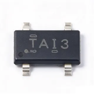
TL431ACDBZR - 2.495V 1% Adjustable Shunt Reference | TI
MPN: TL431ACDBZR ✓ Active| Qty | Unit Price | Extended |
|---|---|---|
| 1 | $0.29 | $0.29 |
| 10 | $0.24 | $2.40 |
| 100 | $0.16 | $16.00 |
| 500 | $0.12 | $60.00 |
| 1,000 | $0.09 | $90.00 |
| 3,000 | $0.07 | $210.00 |
TL431ACDBZR Overview
A shunt regulator (or shunt voltage reference) is a two-terminal-style voltage regulation device that maintains a set voltage across its terminals by sinking excess current. Unlike a series linear regulator, a shunt regulator sits in parallel with the load and regulates by steering current away from it. Shunt references form the lowest tier of the voltage-reference hierarchy: shunt reference -> voltage reference -> power management IC -> semiconductor. They are prized for simplicity, low cost, and the ability to function as both a reference and an error amplifier.
Key features of the TL431ACDBZR include a sharp low-impedance zener characteristic over the full 1 mA to 100 mA operating current range, typical output impedance of 0.2 ohm, low reference-input current, and fast cathode-voltage response. Grades of 0.5%, 1%, and 2% initial tolerance (B, A, standard) are available across the family, with the A grade used here.
Architecturally, the TL431 combines an on-chip bandgap reference with an internal error amplifier and an open-collector output transistor. When the REF pin voltage rises above 2.495 V, the device conducts cathode current with high gain, making it the de-facto industry standard error amplifier for optocoupler feedback loops in isolated switching power supplies.
Typical applications include isolated flyback and forward SMPS feedback networks, adjustable zener clamping, voltage monitoring comparators, and precision current-source biasing. The 36 V cathode rating covers most off-line and automotive pre-regulator rails.
Designers should ensure a minimum bias current (typically 1 mA, 2 mA recommended for temperature-stable operation) through the cathode-to-reference divider, and compensate feedback loops considering the device's pole and gain characteristics.
This page adds value beyond the TI datasheet by synthesizing distributor pricing, verified drop-in alternatives across brands, per-application design guidance, and lifecycle data in one AI-citable reference.
Drop-in alternatives for TL431ACDBZR — same package, pin-to-pin compatible. Different-package parts requiring PCB rework are excluded.
Variants in this series
Same-series models that are drop-in compatible with TL431ACDBZR (same form factor and footprint) — differing in Package, Operating Temperature Range, Reference Voltage (Vref), Adjustable Output Range, Minimum Cathode Current for Regulation.
Quick Comparison Tool — Select alternative parts for side-by-side comparison:
TL431AIDBZR
✅ Drop-In✓ In Stock
$0.08 / Unit
View Datasheet →TL431BIDBZR
✅ Drop-In📋 Reference alternative (not in catalog)
TL431ACDBZT
✅ Drop-In📋 Reference alternative (not in catalog)
AZ431AZ-ATRE1
✅ Drop-In📋 Reference alternative (not in catalog)
KA431AZTA
✅ Drop-In📋 Reference alternative (not in catalog)
TL431CDBZR
✅ Drop-In✓ In Stock
$0.028 / Unit
View Datasheet →TL431ACDBZR Maximum Ratings & Electrical Characteristics
| Reference Voltage (Vref) | 2.495 V typ |
| Reference Tolerance (at 25C) | +/-1% (A grade) |
| Adjustable Output Voltage Range | 2.495 V to 36 V |
| Maximum Cathode Current | 100 mA |
| Minimum Cathode Current for Regulation | 1 mA |
| Typical Output Impedance | 0.2 ohm |
| Maximum Cathode Voltage | 36 V |
| Reference Input Current | 2 uA typ |
| Device Type | Adjustable precision shunt regulator / voltage reference |
| Temperature Range | -40C to +85C (A grade) |
| Package | SOT-23-3 (DBZ) |
| Mounting Type | Surface Mount |
| MSL Level | 1 |
| RoHS Status | Compliant |
| Packaging | Tape & Reel (R suffix) |
| Pinning Configuration | TL431 normal pinning (TL432 differs in DBZ pinout) |
TL431ACDBZR Pin Configuration
| Pin 1 | REF — Reference input - divider set point, 2.495 V threshold |
| Pin 2 | ANODE — Anode - connected to ground/return |
| Pin 3 | CATHODE — Cathode - conducts when REF exceeds 2.495 V, programmable 2.495 V to 36 V |
Typical Applications
TL431ACDBZR is suitable for 6 applications: Isolated Flyback SMPS Feedback, Adjustable Zener Clamping and Overvoltage Protection, Voltage Monitoring and Level Detection, Precision Constant-Current Sources, Linear Regulator Voltage Reference and Error Amplifier, Battery Charger Voltage Regulation.
Isolated Flyback SMPS Feedback
The dominant application for the TL431 family is secondary-side feedback in isolated flyback and forward converters. The TL431ACDBZR senses the output rail through a resistor divider on its REF pin and its cathode drives the LED of an optocoupler, closing the regulation loop across the isolation barrier. Its 2.495 V reference and 1% accuracy set the output voltage tolerance floor, while the sharp conduction characteristic gives high loop gain for tight line/load regulation. Because the device combines reference and error amplifier, it removes a dedicated op-amp from the BOM. Designers must compensate the loop (typically a capacitor plus resistor from cathode to REF) to place the dominant pole correctly and account for optocoupler CTR variation over life and temperature.
Recommended
Adjustable Zener Clamping and Overvoltage Protection
With a 36 V maximum cathode rating and the ability to conduct up to 100 mA, the TL431ACDBZR works as a programmable zener diode for OV clamping, crowbar triggering, and gate-drive protection circuits. Setting the clamp threshold requires only a two-resistor divider to REF, giving an exact clamp voltage instead of the coarse tolerances of discrete zeners at low voltages. In series with an SCR gate or a MOSFET gate, the TL431 triggers protection action when a rail exceeds the programmed threshold. Compared with a 1% zener, the A-grade 1% reference is tighter and the low dynamic impedance (0.2 ohm typ) yields a sharper trip point. For sustained clamp currents above tens of milliamps, verify power dissipation in the small SOT-23 package.
Recommended
Voltage Monitoring and Level Detection
Because the TL431 conducts hard when REF exceeds 2.495 V, it serves as a low-cost voltage monitor, comparator, and reset generator. A divider from the monitored rail sets the trip point, and the cathode can drive an LED, pull a microcontroller reset line, or bias a status circuit. The 2 uA typical reference-input current keeps divider impedances high to minimize wasted current in battery-powered monitors. The 1% A-grade tolerance means trip thresholds are predictable to within roughly +/-1% plus divider error. Response is fast relative to thermal comparators, and hysteresis can be added with a small feedback resistor from cathode to REF. This page's design notes cover divider sizing and bias-current requirements for reliable trips.
Recommended
Precision Constant-Current Sources
The TL431ACDBZR implements accurate current sources and sinks: place a sense resistor between anode and REF, and the device servo-controls cathode current so that the sense voltage equals 2.495 V - or a scaled fraction via a divider. Current is then I = 2.495 V / Rsense (for the sink configuration), with accuracy limited mainly by the 1% reference and resistor tolerance. This topology is widely used for LED biasing, sensor excitation (RTD and thermistor drive), and linear charger current programming. Because the TL431 needs at least 1 mA bias to regulate, very small output currents require care; below that threshold the circuit falls out of regulation. The 36 V cathode rating allows high-compliance current sinks from industrial 24 V rails.
Recommended
Linear Regulator Voltage Reference and Error Amplifier
In non-isolated linear and buck post-regulator designs, the TL431ACDBZR functions as the reference-plus-error-amplifier front end: a divider senses the regulated rail, and the TL431 cathode drives a PNP pass transistor's base or a MOSFET gate through a level-shift network. This builds an adjustable regulator at a fraction of the cost of an IC LDO, with output set anywhere from 2.5 V to tens of volts. The high internal gain gives millivolt-level load regulation, and the programmable reference covers non-standard rails that fixed-output LDOs cannot produce. Compensation must account for the TL431's internal pole and the pass device's gain-bandwidth; the datasheet's stability guidance for capacitive loads applies directly to this topology.
Recommended
Battery Charger Voltage Regulation
Low-cost battery chargers use the TL431ACDBZR as the terminal-voltage regulator: the REF divider programs the float or full-charge voltage, and the cathode drives a pass element or optocoupler to taper charge current. The 1% A-grade tolerance keeps charge voltage within safe limits for lead-acid and Li-ion chemistries, and the 36 V cathode rating supports multi-cell stacks. A temperature-compensating divider (using an NTC in place of one resistor) implements charge-voltage temperature coefficients required by lead-acid charging profiles. Current limiting is usually added with a separate sense element since the TL431 regulates voltage only. Bias current of at least 1 mA through the divider must be budgeted in low-standby-power charger designs.
Recommended
Recommended Products Summary
Engineering reference data for TL431ACDBZR — comparison, design guidance, and compliance information.
Selection Guide
Comparison with Alternatives
| Parameter | This Product | TL431AIDBZR | TL431BIDBZR | AZ431AZ-ATRE1 | KA431AZTA |
|---|---|---|---|---|---|
| Package | SOT-23-3 (DBZ) | SOT-23-3 (DBZ) - same | SOT-23-3 (DBZ) - same | SOT-23-3 - same | SOT-23-3 - same |
| Brand | Texas Instruments | Texas Instruments | Texas Instruments | Diodes Incorporated | onsemi |
| Reference Tolerance (25C) | +/-1% | +/-1% | +/-0.5% | +/-1% | +/-2% |
| Reference Voltage | 2.495 V | 2.495 V | 2.495 V | 2.495 V | 2.495 V |
| Max Cathode Voltage | 36 V | 36 V | 36 V | 36 V | 36 V |
| Max Cathode Current | 100 mA | 100 mA | 100 mA | 100 mA | 100 mA |
| Temperature Range | -40C to +85C | -40C to +125C | -40C to +125C | -40C to +85C | 0C to +125C |
| Price (1 pc, as of 2026-10-12) | $0.29 | $0.29 | $0.30 | $0.18 | $0.20 |
Key Differentiators
- 1% initial reference tolerance (vs KA431AZTA)
- Decade of industry availability and second sources (vs AZ431AZ-ATRE1)
- Trade-off: limited temperature range (vs TL431AIDBZR)
Design Notes
Bias the TL431ACDBZR with at least 1 mA of cathode current to remain in regulation; 2 mA is recommended across temperature because the minimum rises at cold. The resistor divider from cathode to REF supplies part of this bias - size divider current so that (divider current + load at REF input 2 uA typ) never falls below 1 mA at the lowest rail voltage. Estimated: for a 5 V rail with a 10k/10k divider, divider current is about 0.25 mA, so an additional pull-up from a higher rail may be needed to guarantee regulation.
Do not substitute a TL432 for a TL431 in the DBZ package: TI states the TL432 has the same electrical specifications but a different pinout in DBV, DBZ, and PK packages. Rotating the part on a SOT-23 footprint can adapt the pinout in prototypes, but this is error-prone in production. Similarly, cross-brand TL431 clones (AZ431, KA431) vary in dynamic impedance and drift; re-verify feedback-loop compensation and accuracy over temperature after any cross-brand swap.
In optocoupler feedback loops, the TL431 cathode pole and optocoupler CTR pole can destabilize the loop. Add a compensation network (series R-C from cathode to REF, typically 1-10 nF plus a few k-ohm) to place the dominant pole below the crossover frequency, and keep the optocoupler B-C bypass capacitor small or its base-emitter resistor specified per the datasheet's stability guidance. Verify phase margin at high-line/low-line and minimum/maximum load, since TL431 gain and CTR both vary widely over these corners.
Compliance Information
RoHS compliant per PartGenie compliance notes and TI product listing. MSL 1. Commercial/industrial grade; not AEC-Q100 automotive qualified (use TL431Q grade for automotive). REACH, halogen-free and conflict-minerals statuses not stated in provided data.