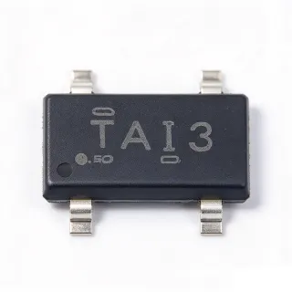
TL431BCDBZR - 2.495V 0.5% Shunt Reference 100mA | TI
MPN: TL431BCDBZR ✓ Active| Qty | Unit Price | Extended |
|---|---|---|
| 1 | $0.09 | $0.09 |
| 10 | $0.08 | $0.80 |
| 100 | $0.06 | $6.00 |
| 500 | $0.05 | $25.00 |
| 1,000 | $0.04 | $40.00 |
TL431BCDBZR Overview
A shunt voltage reference is a programmable Zener-like device that maintains a stable voltage across its terminals when biased with sufficient cathode current; its trip point is set by two external resistors. Within the power-management hierarchy, the shunt reference sits below series regulators, providing a precise reference node for error amplifiers, comparators, and converters. The TL431 family is one of the industry's most widely adopted shunt references, replacing discrete Zener diodes with a single calibrated IC that offers tighter tolerance and lower dynamic impedance.
Key features of the TL431BCDBZR include the tightest initial accuracy in the TL431 family (the B grade, ±0.5% at 25°C), a wide adjustable output from 2.495 V to 36 V, and sink-current capability from 1 mA to 100 mA. Typical output impedance is 0.2 Ω, with low dynamic impedance of approximately 0.05 Ω, giving flat regulation against load and line variation. The C temperature designator specifies the commercial 0 °C to 70 °C operating range.
Architecturally, the TL431 uses a bandgap-referenced error amplifier driving a shunt pass transistor; the internal loop forces VREF (2.495 V) across the reference pin whenever the cathode is biased above the 1 mA minimum. This makes it functionally identical to an adjustable Zener with programmable threshold.
Typical applications include secondary-side feedback error amplification in isolated SMPS designs (paired with an optocoupler), Zener replacements in adjustable references, battery charger voltage detection, overvoltage/undervoltage comparators, and instrumentation reference rails.
Design consideration: always guarantee at least 1 mA of cathode current under all load conditions, including no-load, to stay in regulation; the reference divider impedance should stay below ~10 kΩ or use small bypass capacitance to avoid loop instability.
This page adds distributor pricing, grade-specific drop-in alternatives, and practical cathode-current budgeting notes beyond the datasheet.
Drop-in alternatives for TL431BCDBZR — same package, pin-to-pin compatible. Different-package parts requiring PCB rework are excluded.
Variants in this series
Same-series models that are drop-in compatible with TL431BCDBZR (same form factor and footprint) — differing in Package, Minimum Cathode Current for Regulation, Reference Voltage (Vref), Packaging, Adjustable Output Range.
Quick Comparison Tool — Select alternative parts for side-by-side comparison:
TL431BQDBZR
✅ Drop-In✓ In Stock
$0.07 / Unit
View Datasheet →TL431BIDBZR
✅ Drop-In📋 Reference alternative (not in catalog)
TL431ACDBZR
✅ Drop-In✓ In Stock
$0.07 / Unit
View Datasheet →LM431ACCM3X/NOPB
✅ Drop-In📋 Reference alternative (not in catalog)
KA431AZTA
✅ Drop-In📋 Reference alternative (not in catalog)
AZ431BRTR-E1
✅ Drop-In📋 Reference alternative (not in catalog)
TL431BCDBZR Maximum Ratings & Electrical Characteristics
| Reference Voltage (VREF) | 2.495 V |
| Initial Reference Tolerance | ±0.5% (B grade, at 25°C) |
| Adjustable Output Voltage Range | 2.495 V to 36 V |
| Maximum Cathode Voltage | 36 V |
| Cathode Current Range | 1 mA to 100 mA |
| Typical Output Impedance | 0.2 Ω |
| Dynamic Impedance (typ) | 0.05 Ω (1 mA to 100 mA) |
| Temperature Coefficient (typ) | Approximately 92 ppm/°C |
| Minimum Cathode Current for Regulation | 1 mA (typ) |
| Operating Temperature Range | 0°C to +70°C (C grade) |
| Package | SOT-23-3 (DBZ) |
| Mounting Type | Surface Mount |
| Architecture | Shunt regulator with bandgap error amplifier |
| RoHS Status | Compliant |
| Family Grades Available | 0.5% (B), 1% (A), 2% (standard) |
| Lifecycle Status | Active |
TL431BCDBZR Pin Configuration
| Pin 1 | REF — Reference input (2.495 V internal reference threshold) |
| Pin 2 | ANODE — Anode - connect to low side / ground of the shunt circuit |
| Pin 3 | CATHODE — Cathode - shunt element terminal, sinks 1 mA to 100 mA |
Typical Applications
TL431BCDBZR is suitable for 6 applications: Isolated SMPS Feedback Loop, Zener Diode Replacement, Battery Charger Voltage Detection, Overvoltage / Undervoltage Detection, Instrumentation and Panel Meter Reference, Adjustable Shunt Regulation and Current Sources.
Isolated SMPS Feedback Loop
The TL431BCDBZR is the industry-standard secondary-side error amplifier for isolated flyback and forward converters. Its 2.495 V reference monitors the output rail through a precision resistor divider, and the cathode sinks current from an optocoupler LED that closes the loop to the primary-side PWM controller. The ±0.5% B-grade tolerance maps directly into output-voltage setpoint accuracy - roughly ±75 mV on a 15 V rail - tighter than a 2% standard-grade part can achieve without trim. With 1-100 mA sink range and approximately 0.05 Ω dynamic impedance, it drives typical optocoupler LEDs (1-5 mA) with margin, while the Type-II compensation network placed around the TL431 shapes loop gain for stable phase margin. Minimum cathode current must be guaranteed even at no-load to keep the loop locked.
Recommended
Zener Diode Replacement
The TL431BCDBZR replaces discrete Zener diodes wherever a programmable, tight-tolerance voltage clamp is needed. Unlike a fixed Zener, its threshold is set from 2.495 V to 36 V with two resistors, so one BOM line serves many voltage rails. The ±0.5% initial tolerance dramatically beats typical 5% Zener tolerance, and the approximately 92 ppm/°C drift and 0.2 Ω output impedance outperform low-cost Zeners that exhibit significant dynamic resistance and temperature coefficients. Because it requires only 1 mA minimum bias, it works in low-power metering and battery-operated circuits where Zener bias current (often 5 mA or more) would waste energy. The SOT-23-3 footprint is smaller than most axial Zener land patterns, saving board area in compact designs.
Recommended
Battery Charger Voltage Detection
In charger circuits, the TL431BCDBZR provides a precise voltage threshold that signals when a battery pack has reached its termination voltage. The reference divider is set to the cell chemistry's full-charge voltage; when the pack crosses it, the TL431 pulls its cathode low, driving charge-enable logic, an indicator LED, or the feedback node of a linear charger IC. The ±0.5% tolerance is critical here: on a 4.2 V lithium-ion threshold, 0.5% is only ±21 mV, preventing both dangerous overcharge and premature termination that shortens run time. Operating within 0°C to +70°C with roughly 92 ppm/°C drift keeps the threshold stable across charging environments, and the 36 V cathode rating supports multi-cell stack supervision.
Recommended
Overvoltage / Undervoltage Detection
The TL431BCDBZR makes a compact comparator-with-reference for supply supervision: when a monitored rail crosses the divider-set threshold, the cathode transitions and drives a latch, reset controller, or crowbar. One part replaces a separate reference plus comparator, cutting BOM count and board area in cost-sensitive products. The ±0.5% threshold accuracy on a 2.495 V reference means detection points are known within tens of millivolts - important for protecting 3.3 V and 5 V logic rails before damage occurs. Hysteresis is added with a small positive-feedback resistor around the divider, and the 1 mA minimum cathode current sets the divider budget. Its 36 V maximum directly supervises 12 V, 24 V, and telecom bus rails without pre-scaling beyond the divider.
Recommended
Instrumentation and Panel Meter Reference
Panel meters, DMM front ends, and industrial transmitters use the TL431BCDBZR as an affordable system reference where a premium series reference IC is over budget. The ±0.5% grade sets total-error budgets for 3.5-digit displays, and shunt topology lets the designer buffer it with an op amp to create a low-impedance rail. Compared with Zener-based references, the approximately 92 ppm/°C drift and 0.2 Ω output impedance hold readings stable over temperature and load. Because the output is programmable from 2.495 V upward, one reference powers multiple analog stages with different scaling. The commercial 0°C to +70°C C grade suits indoor instrumentation; use the TL431BIDBZR sibling for extended industrial temperature ranges.
Recommended
Adjustable Shunt Regulation and Current Sources
Beyond voltage clamping, the TL431BCDBZR forms simple precision current sources and sinks: biasing the REF pin from a series resistor forces a fixed voltage across a sense resistor, giving I = 2.495 V / R with ±0.5% accuracy limited mainly by resistor tolerance. This serves LED biasing, sensor excitation, and 4-20 mA transmitter loops in industrial signaling. The 1-100 mA operating range covers most low-current source designs, and the wide 36 V compliance allows high-side placement on 24 V rails. Within 0°C to +70°C, drift of roughly 92 ppm/°C keeps sourced current stable. Adding a PNP or NPN pass transistor around the TL431 extends output current far beyond 100 mA while the TL431 retains control accuracy.
Recommended
Recommended Products Summary
Engineering reference data for TL431BCDBZR — comparison, design guidance, and compliance information.
Selection Guide
Comparison with Alternatives
| Parameter | This Product | TL431BQDBZR | TL431BIDBZR | TL431ACDBZR | KA431AZTA | AZ431BRTR-E1 |
|---|---|---|---|---|---|---|
| Package | SOT-23-3 (DBZ) | SOT-23-3 (DBZ) - same | SOT-23-3 (DBZ) - same | SOT-23-3 (DBZ) - same | SOT-23-3 - same | SOT-23-3 - same |
| Brand | Texas Instruments | Texas Instruments | Texas Instruments | Texas Instruments | onsemi | Diodes Incorporated |
| Reference Voltage (VREF) | 2.495 V | 2.495 V | 2.495 V | 2.495 V | 2.495 V | 2.5 V |
| Initial Tolerance | ±0.5% | ±0.5% | ±0.5% | ±1.0% | ±2% | ±0.5% |
| Adjustable Output Range | 2.495 V to 36 V | 2.495 V to 36 V | 2.495 V to 36 V | 2.495 V to 36 V | 2.495 V to 36 V | 2.5 V to 20 V |
| Max Cathode Current | 100 mA | 100 mA | 100 mA | 100 mA | 100 mA | 100 mA |
| Operating Temperature | 0°C to +70°C | -40°C to +125°C | -40°C to +85°C | 0°C to +70°C | 0°C to +70°C (A grade) | -40°C to +85°C |
Key Differentiators
- Tightest initial accuracy in the TL431 family (vs KA431AZTA)
- Wide 36 V adjustable range (vs AZ431BRTR-E1)
- Extended-temperature drop-in siblings available (vs TL431BQDBZR)
Design Notes
Guarantee a minimum of 1 mA (typical) of cathode current under every load condition, including no-load and lowest input voltage, or the TL431BCDBZR will leave its regulation region and the setpoint will drift. Size the feedback divider so divider current plus cathode load always exceeds the minimum - designing for 2 mA provides margin over temperature. In SMPS feedback, remember that the optocoupler LED current must not steal so much headroom that the TL431 cathode falls below 1 mA at maximum duty.
Place the REF divider resistors close to the TL431 and keep the REF node trace short to minimize noise pickup in high-dv/dt SMPS environments. If the divider Thevenin impedance exceeds about 10 kΩ, add a small compensation/bypass network (100 nF or a Type-II RC network) between REF and cathode to prevent loop oscillation - the TL431 is a high-gain amplifier and pure capacitive loading without a series resistor can destabilize it. Keep the cathode trace away from switching nodes and provide a solid anode/ground return.
Do not substitute the TI TL432B for the TL431B without checking the pinout: per the TI datasheet, TL432 has exactly the same electrical specifications but different pin assignments in the DBV, DBZ, and PK packages. Similarly, cross-brand equivalents such as KA431 and AZ431 differ in reference tolerance (2% for KA431AZTA versus ±0.5% here) and adjustable maximum (20 V for AZ431BRTR-E1 versus 36 V), so verify that the accuracy grade and voltage ceiling meet the circuit's error budget before dropping them onto the same footprint.
Compliance Information
RoHS compliant and lead-free per DigiKey and LCSC listings. AEC-Q100 qualification not applicable to the C-grade commercial part; use TL431BQDBZR family for extended-temperature qualification.