
Texas Instruments

TUSB212RWBR - USB 2.0 HS Signal Conditioner | Texas Instruments

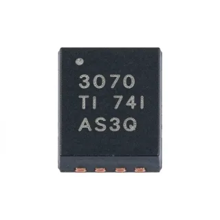
MPN: TUSB212RWBR ✓ Active
12-X2QFN (1.6 mm x 1.6 mm) Package USB 2.0 High-Speed Speed
MOQ: 1 |

TUSB212RWBR Overview

Texas Instruments TUSB212RWBR is a USB 2.0 High-Speed signal conditioner with DC boost, packaged in a 12-X2QFN surface-mount package measuring 1.6 mm by 1.6 mm. It is designed to compensate for intersymbol interference caused by signal loss in a transmission channel. The device applies programmable AC boost and DC boost to restore degraded high-speed data signals while remaining agnostic to USB Low-Speed and Full-Speed traffic.

A USB signal conditioner is a specialized interface IC that improves an already transmitted USB differential signal without changing the protocol implemented by the USB host, hub, or peripheral. Its position in the signal path is between the transmitter and a lossy channel. This makes the TUSB212RWBR part of the broader USB interface hierarchy: USB 2.0 interface IC, signal conditioning IC, redriver, and ultimately a semiconductor-based connectivity device.

The principal feature of the TUSB212RWBR is programmable signal AC boost combined with DC boost. AC boost restores high-frequency signal amplitude lost through channel attenuation, while DC boost helps maintain the differential voltage required for reliable high-speed signaling. The manufacturer describes the implementation as patent pending and identifies USB On-The-Go compatibility as an additional design feature. Low-Speed and Full-Speed signal characteristics remain unaffected by the conditioning function.

TUSB212RWBR is intended for USB 2.0 systems where trace losses, connector transitions, cable segments, or routing discontinuities reduce High-Speed eye margin. Conditioning is normally applied to the D+ and D+ differential pair as a complete pair rather than to either conductor independently. The correction must be tuned from measured eye diagrams because excessive boost can increase edge distortion, jitter, or emissions instead of improving receiver recovery.

Typical deployments include USB hubs, cable assemblies, peripheral boards, host adapters, test equipment, and USB-to-storage or USB-to-network interfaces. In a hub, the conditioner can be placed near an upstream port so the signal entering a long cable is restored before attenuation becomes significant. In a peripheral, it can compensate for PCB routing from a connector to a USB controller.

When applying the device, preserve the USB differential impedance recommended by the manufacturer and keep the D+ and D+ routes coupled and symmetric. Decoupling and boost configuration should follow the manufacturer reference layout. Confirm compliance through eye-height, jitter, rise-time, and emissions measurements because channel length, connector geometry, and host behavior determine the useful correction amount.

This product page combines the manufacturer's USB 2.0 signal-conditioning description, exact TUSB212RWBR package information, extracted distributor pricing, and practical replacement analysis. It also distinguishes confirmed drop-in candidates from unsupported package or functional substitutions so engineers can make a PCB-level decision without relying on generic USB redriver recommendations.

Drop-in alternatives for TUSB212RWBR — same package, pin-to-pin compatible. Different-package parts requiring PCB rework are excluded.

TUSB214IRWBR

✅ Drop-In
📦 12-X2QFN (1.6 mm x 1.6 mm)
Different family MPN with the same 12-pin compact QFN format; the comparison source identifies package and compliance similarities, while boost-control and electrical-limit differences must still be verified.

📋 Reference alternative (not in catalog)

TUSB214IRWBT

✅ Drop-In
📦 12-X2QFN (1.6 mm x 1.6 mm)
Different family and tape-and-reel order code with the same 12-pin compact QFN format; the available comparison identifies package similarity, but detailed pin and AC/DC boost differences require datasheet confirmation.

📋 Reference alternative (not in catalog)

TUSB212RWBR Specifications

Product Type USB 2.0 High-Speed Signal Conditioner
Supported USB Speed USB 2.0 High-Speed
Signal Compensation Function Programmable AC boost and DC boost
Target Signal Distortion Intersymbol interference from transmission-channel loss
Low-Speed Behavior Unaffected by the High-Speed compensation
Full-Speed Behavior Unaffected by the High-Speed compensation
USB On-The-Go Compatibility Compatible
Package 12-X2QFN (1.6 mm x 1.6 mm)
Mounting Type Surface Mount
Pin Count 12 pins
Production Data Marking PRODUCTION DATA
Manufacturer Document Revision Revision A, September 2017
Maximum Data Rate 480 Mb/s
RoHS Status Compliant

TUSB212RWBR 12-x2qfn (1.6 mm x 1.6 mm) Pin Configuration Guide

Pin configuration for TUSB212RWBR (12-x2qfn (1.6 mm x 1.6 mm) package). Pin numbering, functions, and connection diagrams are defined in the manufacturer datasheet. Refer to it for the exact footprint and soldering guidelines.

12-x2qfn (1.6 mm x 1.6 mm) package pinout diagram for TUSB212RWBR

No detailed pinout data available for TUSB212RWBR.

Refer to the datasheet for full pin configuration.

Typical Applications

TUSB212RWBR is suitable for 6 applications: USB 2.0 Hub Port Conditioning, USB Docking-Station Interconnect, External USB Storage Adapter, USB-to-Network Adapter, USB Host and Peripheral Test Fixture, Camera and Imaging USB Link.

🌐

USB 2.0 Hub Port Conditioning

The TUSB212RWBR is suitable for conditioning a degraded USB 2.0 High-Speed differential pair at a hub port. Place the device near the connector or upstream transmitter so attenuation has not yet reached its maximum. Its programmable AC boost restores high-frequency content lost through routing, while DC boost helps maintain differential signal amplitude. This can improve receiver eye margin in long traces or connector-heavy designs, although the boost settings must be established from measured eye and jitter data rather than maximum correction.

🖥️

USB Docking-Station Interconnect

A docking station combines connectors, internal cables, and long PCB routes that can introduce USB High-Speed loss. The TUSB212RWBR can be placed upstream of the affected connector to compensate for intersymbol interference using programmable AC and DC boost. Keeping the conditioner close to the transmitter limits the amount of degradation it must correct. Validate the implementation with the exact cable and display accessory because connector transitions and device wake behavior can materially change the usable eye margin.

💾

External USB Storage Adapter

The TUSB212RWBR can compensate for High-Speed loss between a USB storage controller and a connector or internal cable in an external adapter. Its AC boost targets the high-frequency attenuation that closes the data eye, while DC boost supports differential signal amplitude. Place the conditioner on the transmitting side where channel loss remains manageable and confirm performance with eye-height, jitter, and compliance testing. The Low-Speed and Full-Speed paths remain unaffected by the High-Speed compensation function.

🌐

USB-to-Network Adapter

In a USB-to-network adapter, connector transitions and internal routing may reduce the usable USB 2.0 High-Speed eye before data reaches the Ethernet interface controller. The TUSB212RWBR can restore the affected differential pair with programmable AC and DC boost. It is especially useful where the PCB route between the USB connector and the host controller is lengthy or contains test points. Confirm pin assignments, reference layout, and USB compliance measurements against the manufacturer datasheet before release.

🧪

USB Host and Peripheral Test Fixture

The TUSB212RWBR can support a USB 2.0 test fixture that reproduces the losses of cables, connectors, and realistic board routing. Its programmable AC boost and DC boost allow controlled compensation while the fixture evaluates eye height, jitter, and data recovery. The device is useful when engineers need repeatable channel emulation without changing the transmitter. Because the conditioner affects High-Speed traffic, Low-Speed and Full-Speed enumeration tests should be run separately to verify that their signal characteristics remain unaffected.

📷

Camera and Imaging USB Link

A camera or imaging peripheral can use the TUSB212RWBR when its USB High-Speed link shows degradation between an upstream connector and the device controller. The conditioner restores high-frequency signal content and differential amplitude, helping maintain a larger receiver eye across a lossy route. Place it close to the transmitter and keep the pair length matched. Because image-transfer errors can originate in both the data link and device firmware, confirm the physical improvement through eye and jitter measurements before attributing a performance gain solely to the signal conditioner.

What is the TUSB212RWBR?
The TUSB212RWBR is a Texas Instruments USB 2.0 High-Speed signal conditioner with programmable AC boost and DC boost. According to the manufacturer product page, it compensates for intersymbol interference caused by signal loss in a transmission channel. It is intended to restore degraded USB High-Speed signals while leaving USB Low-Speed and Full-Speed signal characteristics unaffected, and it is supplied in a 12-X2QFN package measuring 1.6 mm by 1.6 mm.
Where can I download the TUSB212RWBR datasheet PDF?
The official TUSB212RWBR datasheet PDF is available from Texas Instruments at https://www.ti.com/lit/gpn/TUSB212. The manufacturer identifies the document as Revision A, revised September 2017, and marks the device as production data. A third-party copy also appears on AllDatasheet, but the TI link is the preferred source for ordering information, pin definitions, electrical characteristics, and the recommended application layout.
Where can I find the TUSB212RWBR pinout?
The TUSB212RWBR pinout is documented in the manufacturer datasheet at https://www.ti.com/lit/gpn/TUSB212. The exact orderable TUSB212RWBR uses the 12-X2QFN package, also identified by distributors as 12-X2QFN or 12-XFQFN. Use the datasheet pin-description and land-pattern tables when assigning nets, and preserve the exposed-pad and thermal-via requirements shown in the recommended package layout.
What USB speeds does the TUSB212RWBR affect?
The TUSB212RWBR compensates USB 2.0 High-Speed signals and does not alter USB Low-Speed or Full-Speed signal characteristics. Texas Instruments describes the implementation as agnostic to Low-Speed and Full-Speed traffic while applying correction to the impaired High-Speed differential signal. This makes the device suitable for a mixed-speed USB path in which only the 480 Mb/s channel suffers significant loss.
How do AC boost and DC boost work in the TUSB212RWBR?
The TUSB212RWBR uses programmable AC boost and DC boost to restore signal amplitude affected by transmission-channel loss. AC boost restores the high-frequency content needed for reliable High-Speed eye opening, while DC boost helps maintain differential signaling amplitude. The manufacturer states that the design compensates intersymbol interference; engineers should select the boost settings from measured eye and jitter behavior rather than applying maximum correction unconditionally.
When should I use the TUSB212RWBR in a USB design?
Use the TUSB212RWBR when measurements show that USB 2.0 High-Speed loss is reducing eye height or increasing jitter across a PCB route, connector transition, internal cable, or external cable path. It is most useful where the transmitter output cannot maintain adequate receiver margin without channel equalization. The conditioner should remain near the degraded signal source, with the D+ and D+ traces routed as a controlled-impedance differential pair.
TUSB212RWBR vs TUSB214IRWBR: which one is better?
The TUSB212RWBR and TUSB214IRWBR are both identified by comparison sources as Texas Instruments USB interface solutions, but their manufacturer part numbers indicate separate family members. TUSB212RWBR is specifically described as a USB 2.0 High-Speed conditioner with programmable AC and DC boost. TUSB214IRWBR may be considered only after verifying its exact electrical limits, pin functions, boost range, and package mapping against the target design; generic similarity does not by itself prove drop-in equivalence.
What is the difference between TUSB212RWBR and TUSB214IRWBT?
The TUSB212RWBR and TUSB214IRWBT are different orderable devices, and the final letters identify different package or ordering configurations rather than interchangeable functional options. The TUSB212RWBR is a 12-X2QFN USB 2.0 High-Speed signal conditioner with programmable AC boost and DC boost. Before using TUSB214IRWBT in a replacement, compare its pinout, package dimensions, electrical ratings, configuration method, and USB signal behavior against the manufacturer datasheets.
When should I choose TUSB212RWBR over another USB redriver?
Choose the TUSB212RWBR when the design specifically needs a Texas Instruments USB 2.0 High-Speed conditioner that compensates intersymbol interference while leaving Low-Speed and Full-Speed traffic unaffected. Its programmable AC and DC boost features provide channel-specific correction, and the manufacturer identifies USB On-The-Go compatibility. Select a different redriver only when another device offers a required electrical range, package, qualification, or channel-compensation architecture.
Is the TUSB212RWBR suitable for USB hubs and docking stations?
The TUSB212RWBR is suitable for USB hub and docking-station signal paths that show High-Speed degradation from connectors, internal cables, or PCB routing. It can be placed near a port so the differential signal is conditioned before channel loss accumulates. The design must preserve controlled-impedance routing, and the correction should be validated through eye-height and jitter measurements under the intended USB host, cable, and peripheral combinations.
What can replace the TUSB212RWBR?
The closest documented replacement candidates are the Texas Instruments TUSB214IRWBR and TUSB214IRWBT, which are compared directly with the TUSB212RWBR by an electronics comparison source. However, a valid drop-in replacement must match the exact package, pin functions, supply requirements, boost-control interface, and USB High-Speed electrical behavior. Confirm those details in the manufacturer datasheets before changing the PCB or production BOM.
Is there a cross-brand equivalent for the TUSB212RWBR?
No cross-brand drop-in equivalent is established by the available component cross-reference information for the TUSB212RWBR. The documented candidates are from Texas Instruments, so a second-source replacement requires a separate package, pin, and electrical verification rather than relying on generic USB-redriver similarity. Use the Request a Quote form on this page when a source needs documented drop-in alternatives or engineering review of an unverified candidate.
What are the key specifications of TUSB212RWBR that engineers should know?
The key TUSB212RWBR specifications are its USB 2.0 High-Speed signal-conditioning function, programmable AC boost and DC boost, compensation of transmission-channel intersymbol interference, unchanged Low-Speed and Full-Speed behavior, USB On-The-Go compatibility, and 12-X2QFN surface-mount package. The package is identified as 1.6 mm by 1.6 mm. Detailed voltage, current, temperature, and boost-range limits must be taken from the manufacturer datasheet.
Where can I buy TUSB212RWBR and what is its lead time?
Use the Request a Quote form on this page to request current TUSB212RWBR availability, minimum order quantity, lead time, and shipment options. The exact orderable part is listed as a Texas Instruments 12-X2QFN signal-processing interface, while another distributor listing reports inventory of 2,792 pieces but marks lead time as to be confirmed. Current lead time should therefore be confirmed at order time rather than inferred from historical stock.
What is the price of TUSB212RWBR?
Current TUSB212RWART pricing is presented through the Request a Quote form on this page so the commercial response reflects current inventory, quantity, and currency requirements. The structured pricing evidence records a USD quantity-break listing for the exact TUSB212RWBR MPN, including the one-piece tier and larger production quantities. Use the quote form to confirm the applicable quantity, delivery terms, and current unit price.
Is TUSB212RWBR in stock?
TUSB212RWBR inventory is listed by at least one distributor, but stock levels and lead time can change rapidly. The Request a Quote form on this page is the appropriate route for confirming the current quantity available for your required order quantity and packaging. When evaluating availability, specify the exact MPN TUSB212RWBR and whether production quantities or prototype quantities are needed.
How should the TUSB212RWBR be laid out for USB signal integrity?
Place the TUSB212RWBR close to the point where channel loss begins and route D+ and D+ as a short, symmetric, controlled-impedance differential pair. Keep the boost configuration, supply decoupling, ground connection, and device lands consistent with the manufacturer reference layout. Verify the completed design with eye-height, jitter, rise-time, and emissions measurements because excessive AC boost can improve one eye metric while degrading another.

Engineering reference data for TUSB212RWBR — comparison, design guidance, and compliance information.

Selection Guide

Choose the TUSB212RWBR when the design needs explicit USB 2.0 High-Speed channel correction using programmable AC boost and DC boost, particularly where measured trace or cable loss reduces eye margin. It is also appropriate when Low-Speed and Full-Speed traffic must pass through the same physical connection without being altered by the High-Speed conditioner. Consider TUSB214IRWBR when its complete datasheet confirms the required pinout, boost range, supply limits, and channel performance match the target design. Consider TUSB214IRWBT when its packaging and ordering configuration are suitable, but verify it as a distinct orderable device rather than treating the final suffix as interchangeable. No cross-brand candidate is established by the available evidence. In every case, make the final decision using eye-height, jitter, rise-time, emissions, and USB compliance results with the actual cable, connector, host, and peripheral.

Comparison with Alternatives

Parameter This Product TUSB214IRWBR TUSB214IRWBT
Package 12-X2QFN (1.6 mm x 1.6 mm) 12-X2QFN (1.6 mm x 1.6 mm) 12-X2QFN (1.6 mm x 1.6 mm)
Brand Texas Instruments Texas Instruments Texas Instruments
Primary Function USB 2.0 High-Speed signal conditioner Texas Instruments USB interface solution Texas Instruments USB interface solution
RoHS Compliance Compliant Compliant Compliant
Mounting Type Surface Mount Surface Mount Surface Mount

Key Differentiators

  • Channel correction combines programmable AC boost with DC boost (vs TUSB214IRWBR)
  • Low-Speed and Full-Speed paths remain unaffected (vs TUSB214IRWBT)
  • USB On-The-Go compatibility is identified by the manufacturer (vs TUSB214IRWBR)

Design Notes

Treat D+ and D+ as one controlled-impedance differential pair. Place the TUSB212RWBR near the transmitter or port where attenuation begins, and minimize the distance between the device and the relevant connector or lossy channel. Use the manufacturer pin and reference-layout information for land patterns and avoid adding test pads or branch stubs that create discontinuities. Confirm improvement through eye-height and jitter measurements with the intended cable and peripheral attached.

Do not configure maximum AC and DC boost without measurement. Excessive high-frequency boost can alter edge rate, increase jitter, or create emissions even when a short test fixture appears to show a larger eye. Start from a conservative correction, then tune using the worst-case channel, host, device, temperature, and supply conditions. The manufacturer states that Low-Speed and Full-Speed behavior remains unaffected, so evaluate those speeds separately from the High-Speed compensation loop.

Use the manufacturer datasheet for the exact 12-X2QFN land pattern, exposed-pad connection, thermal vias, and supply-decoupling arrangement. The available 12-X2QFN package is only 1.6 mm by 1.6 mm, so solder mask, paste, and assembly capability should be reviewed before release. Keep the High-Speed route short and symmetrical, provide a continuous return path, and isolate any AC or DC boost configuration components from sensitive analog or clock circuitry.

USB High-Speed edge content can radiate even when functional data transfer passes. Maintain continuous reference planes, avoid split-plane transitions beneath the differential pair, and apply the manufacturer's recommended decoupling. After boost tuning, verify radiated and conducted emissions because improving the receive eye with excessive edge emphasis can increase electromagnetic noise. Use the same test arrangement for both eye analysis and emissions measurement.

Compliance Information

RoHS
Compliant
REACH
Unknown
AEC-Q100
Unknown
Lead Free
Unknown
Halogen Free
Unknown
Conflict Minerals
Unknown

The exact-MPN distributor listing identifies the TUSB212RWBR as ROHS3 and RoHS compliant. No specific REACH, AEC-Q100, halogen-free, or conflict-minerals statement was confirmed for the target part. A comparison source reports RoHS and REACH compliance for the listed TUSB214 alternatives.

Related Searches

TUSB212RWBR datasheet TUSB212RWBR pinout TUSB212RWBR datasheet pdf TUSB212RWBR equivalent TUSB212RWBR replacement TUSB212RWBR cross reference TUSB212RWBR vs TUSB214IRWBR TUSB212RWBR vs TUSB214IRWBT TUSB212RWBR 12-X2QFN pinout TUSB212RWBR USB signal conditioner TUSB212RWBR AC DC boost Texas Instruments TUSB212RWBR TUSB212RWBR price TUSB212RWBR stock TUSB212RWBR USB hub application

Related Components & Terms

Texas Instruments TUSB212RWBR TUSB214IRWBR TUSB214IRWBT USB 2.0 USB High-Speed USB Low-Speed USB Full-Speed USB On-The-Go USB signal conditioner USB redriver Interface IC Semiconductor Intersymbol interference Programmable AC boost DC boost Signal integrity Differential pair 12-X2QFN QFN family Surface mount RoHS REACH USB hub Docking station
Quick Quote RFQ
Fill in complete details — our sales team will respond within 24 hours
Part Number Manufacturer Package QTY Target Price Extended
✓
Quote submitted!

We will respond to your email within 24 hours

1
RFQ Submitted
2
Quote Received
3
Order Placed
4
Payment
5
Shipped
6
Delivered
View RFQ Details