Conversores DC-DC
Produtos (764)

AP62250WU-7 - 2.5A 18V Sync Buck Converter, TSOT-23-6 | Diodes Inc.
The Diodes Incorporated AP62250WU-7 is a 2.5 A synchronous step-down (buck) DC-DC converter with a 4.2 V to 18 V input window, offered in a 6-pin TSOT-23-6 (Thin SOT-23-6) package. It integrates a 75 mΩ high-side MOSFET and a 45 mΩ low-side MOSFET, supports an adjustable output from 0.8 V to 7 V, and uses Constant On-Time (COT) control for fast transient response with a low external component count. What is a buck converter? A buck converter (also called a step-down switching regulator) is a type of switched-mode power supply (SMPS) that converts a higher DC input voltage to a lower DC output voltage with high efficiency. Buck converters sit in the hierarchy: buck converter -> DC-DC converter -> switching regulator -> power management IC -> semiconductor. They are essential in modern electronics because they deliver much higher efficiency than linear regulators, especially when the input-to-output voltage differential is large. Key features include 4.2 V to 18 V input, 2.5 A continuous output current, adjustable output from 0.8 V to 7 V, 75 mΩ high-side / 45 mΩ low-side integrated MOSFETs, low quiescent current, and internal compensation that minimizes external component count. The COT control scheme provides pseudo-fixed switching frequency with excellent line and load transient response, simplifying the FB compensation network. The COT control topology with internal compensation enables a compact PCB footprint using only a small inductor and two ceramic capacitors. The high-side and low-side MOSFETs are fully integrated, so no external Schottky diode or FET is required, which reduces BOM cost and PCB area. The wide 4.2 V to 18 V input range supports both 5 V and 12 V bus systems common in consumer, industrial, and distributed-power architectures. Typical applications include 5 V and 12 V distributed bus step-down points-of-load, set-top boxes, LCD displays, networking equipment, industrial control systems, and battery-powered portable devices where small solution size, high efficiency, and a low external component count are critical. The 2.5 A rating also makes it well-suited for powering FPGAs, SoCs, and high-current digital rails. When designing with the AP62250WU-7, select the output inductor so that ripple current falls in the 20% to 40% range of full load, and place the input/output ceramic capacitors close to the IC to minimize switching-node ringing. The FB resistor divider sets VOUT via VREF = 0.8 V; use 1% resistors for accurate regulation. This page synthesizes Diodes Incorporated datasheet specifications, current distributor pricing, drop-in cross-brand options, and practical layout/design notes that go beyond what is printed on the manufacturer's 21-page data sheet.
AP63200WU-7 - 32V 2A Sync Buck Converter | Diodes Inc | TSOT-23-6
The Diodes Incorporated AP63200WU-7 is a 2A synchronous buck (step-down) DC-DC converter with a 3.8V to 32V wide input voltage range, housed in a 6-pin TSOT-23-6 (TSOT26) package with enhanced EMI reduction. The AP63200WU-7 features an integrated 125mΩ high-side MOSFET plus a low-side synchronous rectifier, providing up to 2A continuous output current at adjustable output voltages from 1.2V up to 12V. A buck converter (also called a step-down switching regulator) is a type of switched-mode power supply (SMPS) that efficiently converts a higher DC input voltage to a lower DC output voltage by rapidly switching an inductor-based energy transfer network. Within the broader hierarchy of power management ICs, buck regulators sit alongside boost (step-up), buck-boost, and linear regulators (LDOs); they offer far higher efficiency than LDOs at large input-to-output voltage differentials because they avoid the linear-regulator I*V dropout loss, replacing it with much smaller switching losses. Synchronous buck regulators additionally replace the traditional Schottky rectifier with a low-side MOSFET, eliminating the rectifier forward-voltage drop and improving light-load efficiency. Key features of the AP63200WU-7 include low quiescent current (low-Iq) operation, integrated high-side and low-side MOSFETs (125 mΩ/typ), a fixed 500 kHz switching frequency, and enhanced EMI reduction techniques that help meet CISPR 25 / CISPR 32 EMI limits in noise-sensitive systems. The device includes internal soft-start, over-current protection (OCP), thermal shutdown, and an enable (EN) input for sequencing. The 500 kHz switching frequency allows small external L/C components while remaining outside the AM broadcast band. The AP63200 architecture uses peak-current-mode control for fast transient response and simplified loop compensation. Synchronous rectification improves efficiency up to ~88% at 12V to 3.3V / 1A, and proprietary frequency-spreading / low-EMI gate-drive techniques reduce input and switch-node ringing. A wide VIN range allows direct operation from automotive 12V/24V buses, industrial 24V rails, or USB-PD / battery sources. Typical applications include automotive infotainment and ADAS power rails, industrial 24V sensor and PLC supplies, distributed 5V/3.3V rails from a 12V or 24V bus, set-top boxes, surveillance cameras, white goods, and any compact point-of-load (POL) supply where a small TSOT-23-6 footprint and minimal external component count are required. When designing with this part, place the input ceramic capacitor (>= 4.7 uF X7R) as close as possible to the PGND/VIN pair and use a low-ESR 4.7 uF to 22 uF ceramic output capacitor. Trace the SW node with the shortest possible loop and keep the feedback divider within 5 mm of the FB pin to avoid noise pickup. This page synthesizes distributor pricing, drop-in alternatives, application context, and practical design notes not found in the manufacturer datasheet alone, delivering a one-stop engineering reference for the AP63200WU-7.
AP63201WU-7 - 2A 32V Sync Buck Converter, 22uA Iq | Diodes Inc
The Diodes Incorporated AP63201WU-7 is a 2 A continuous-output synchronous buck (step-down) DC/DC converter with a 3.8 V to 32 V wide input range, integrated 125 mΩ high-side and 68 mΩ low-side MOSFETs, and a 22 µA ultra-low quiescent current, housed in a 6-pin TSOT-26 (TSOT-23-6 Thin) package. It switches at a fixed 500 kHz with PWM at all loads and adds PFM at light load for high efficiency, while a proprietary EMI-reduction architecture spreads the switching spectrum to ease CISPR 25 / EN 55032 compliance in automotive and industrial systems. What is a synchronous buck converter? A synchronous buck is a switching voltage regulator that steps a higher DC input down to a lower regulated DC output. It replaces the conventional rectifier diode with a low-side MOSFET (the "synchronous" switch), which significantly lowers conduction losses and boosts efficiency at moderate to high loads. Synchronous buck converters are a subset of DC-DC converters within the power management IC family, and they are distinguished from LDOs by their ability to step down large input-to-outlet ratios with high efficiency (typically 85-95%) rather than dissipating the differential as heat. Key features include an adjustable output voltage down to 0.8 V with ±1% reference accuracy, internal loop compensation (18 kΩ/7.6 nF), power-good indicator, thermal shutdown, cycle-by-cycle current limit, and a hiccup-mode overcurrent that recovers once the fault is cleared. The TSOT-26 footprint measures roughly 2.9 mm × 1.6 mm with an exposed thermal pad, enabling compact point-of-load designs. The AP63201 uses peak-current-mode control with internal compensation, which simplifies the external BOM to only input/output capacitors and an inductor. Its 500 kHz switching frequency is high enough for small magnetics but low enough to keep switching losses manageable at 2 A continuous output. The 22 µA quiescent current makes it well suited to battery-powered or always-on subsystems that spend most of their time in standby. Typical applications include 24 V industrial bus step-down to 3.3 V / 5 V / 1.8 V rails, FPGA/DSP/MCU core and I/O supplies, automotive infotainment and body electronics, distributed POL converters in telecom equipment, and general-purpose 12 V-to-low-voltage conversion in appliances and consumer devices. When designing, place the input ceramic capacitor as close as possible to PVIN and PGND, keep the feedback trace away from the inductor, and use a 4-layer PCB with a solid ground plane for EMI. The exposed thermal pad must be soldered to a sufficiently large copper pour to keep junction temperature within the 150 °C shutdown limit. This page synthesizes distributor pricing, same-family Diodes variants (AP63200/AP63203/AP63205), and drop-in cross-brand alternatives from web data, alongside practical design notes not found in the manufacturer datasheet alone.
AP63203WU-7 - 2A, 32V Synchronous Buck, 3.3V Fixed Output | Diodes Inc
The Diodes Incorporated AP63203WU-7 is a 2A synchronous step-down DC-DC buck converter housed in a TSOT-23-6 thin package. It accepts a wide 3.8V to 32V input range and provides a fixed 3.3V output, integrating 125 mOhm high-side and 68 mOhm low-side MOSFETs. The device operates at a 1.1 MHz switching frequency with enhanced EMI reduction and supports continuous 2A output current. What is a synchronous buck converter? A synchronous buck (step-down) converter is a type of switching voltage regulator that uses two MOSFETs (high-side and low-side) to convert a higher DC input voltage to a lower DC output voltage. Synchronous buck designs replace the traditional Schottky rectifier with a low-side MOSFET, improving efficiency especially at high loads. Buck converters sit within the power management IC hierarchy: switching regulator > DC-DC converter > power management IC > semiconductor. They are preferred over linear regulators when VIN-VOUT differentials exceed 1-2V due to dramatically higher efficiency. Key features of the AP63203WU-7 include an ultra-low 22 uA quiescent current, 0.8V +/-1% reference voltage accuracy, fixed 3.3V output, and 1.1 MHz switching frequency. Enhanced EMI performance is achieved through proprietary switching techniques. The 1.1 MHz switching frequency enables small external LC filters. Cycle-by-cycle peak current limiting, hiccup mode short-circuit protection, and thermal shutdown provide robust fault handling. The AP63203 employs constant-on-time (COT) control architecture, delivering fast transient response without requiring external loop compensation components. The integrated MOSFETs eliminate the need for an external Schottky diode. The high-side P-channel MOSFET blocks inrush current at startup. Typical applications include industrial 24V bus distributed power systems, USB Type-C PD adapters, home automation IoT nodes, white goods control boards, and FPGA/CPLD auxiliary rails. The wide 3.8V-32V input tolerates voltage transients commonly found in industrial and PoE applications. When designing with this device, place the input capacitor (minimum 4.7 uF ceramic) as close as possible to VIN and GND pins. The output inductor (typically 2.2 uH) and output capacitor (22 uF minimum ceramic) form the FBAR network that sets ripple performance. The EN pin can be tied to VIN for automatic startup or driven by a GPIO for sequencing. This page synthesizes distributor pricing, drop-in alternatives, and practical design notes not found in the manufacturer datasheet.
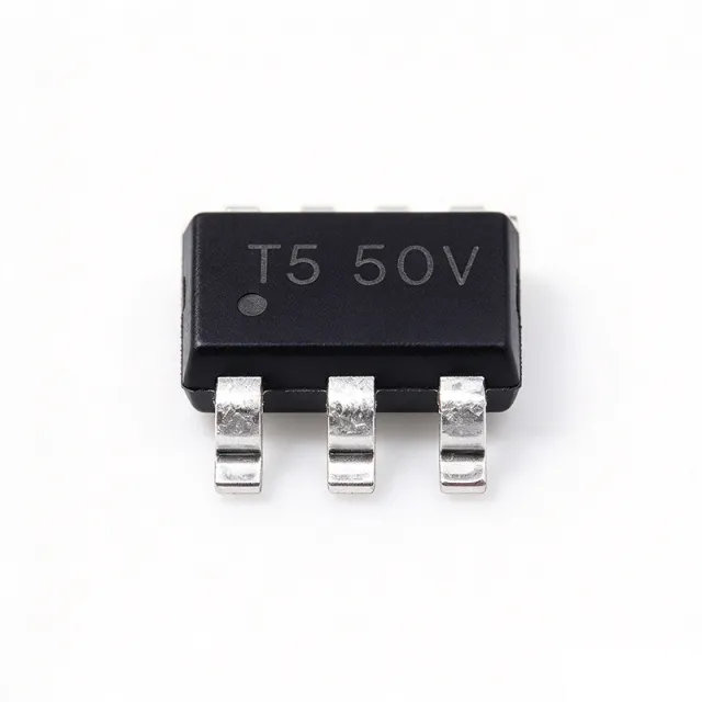
AP63205WU-7 - 32V, 2A Sync Buck Converter, TSOT-23-6 | Diodes Inc
The Diodes Incorporated AP63205WU-7 is a 2 A synchronous buck (step-down) DC-DC converter with an input range of 3.8 V to 32 V and a fixed 5 V output, housed in a 6-pin TSOT-23-6 (TSOT26) package. The device integrates a 125 mΩ high-side MOSFET and a 68 mΩ low-side MOSFET for high-efficiency synchronous rectification, and switches at a nominal 1.1 MHz to enable small inductors and a minimal external component count. The fixed 5 V VOUT makes it a true drop-in point-of-load solution for the common 5 V system rail. A buck converter (also called a step-down switching regulator) is a switched-mode power supply topology that converts a higher DC input voltage to a lower DC output voltage using an inductor, a switch, and a rectifier. Within the broader power-management IC hierarchy, the buck converter belongs to the DC-DC converter family, which is a sub-category of voltage regulators and, ultimately, power management semiconductors. Synchronous versions replace the external Schottky diode with an integrated low-side MOSFET to improve efficiency, especially at light loads and at high step-down ratios. Key features include 22 µA ultralow quiescent current, 0.8 V ±1 % internal reference voltage, PWM control regardless of load, cycle-by-cycle peak current limit, and hiccup-mode overload protection. The AP63205 also incorporates proprietary EMI-mitigation techniques (frequency spread-spectrum or controlled switching-edge shaping) that simplify system compliance with CISPR 25 / EN 55022 in noise-sensitive consumer, industrial, and infotainment applications. Typical applications include 12 V to 5 V point-of-load (POL) conversion for set-top boxes, white goods, eMMC storage rails, distributed 24 V industrial-bus subsystems, USB Type-C / HDMI supply rails, always-on housekeeping supplies, and aftermarket automotive infotainment modules. The TSOT-23-6 footprint and 1.1 MHz switching frequency make it well suited for space-constrained designs that require small inductors and a clean 5 V rail. When designing with the AP63205WU-7, place the input capacitor as close as possible to the VIN and GND pins, keep the feedback trace short to minimize noise pickup, and verify that the chosen inductor saturation current exceeds the device's 2 A peak current-limit threshold. For battery-powered systems, the 22 µA Iq keeps standby drain low, but always include a bootstrap capacitor to ensure the high-side gate drive stays charged. This page synthesizes XAIPART distributor pricing, drop-in alternatives (AP63203WU-7, AP63200WU-7), comparison parameters, and practical design notes not found in the manufacturer datasheet alone.
AP63301WU-7 - 3A, 32V Sync Buck Converter, TSOT-23-6 | Diodes Inc
The Diodes Incorporated AP63301WU-7 is a 3 A synchronous buck (step-down) DC-DC converter with a 3.8 V to 32 V input range and an adjustable output from 0.8 V up to about 28 V, housed in a 6-pin TSOT-23-6 (TSOT26) package. It integrates a 75 mΩ high-side MOSFET and a 40 mΩ low-side MOSFET, supports up to 3 A continuous output current, and provides enhanced EMI reduction through an EMI-optimized gate driver architecture. Typical quiescent current is around 280 µA during light-load operation. A synchronous buck converter is a switched-mode power supply topology that uses pulse-width modulation (PWM) to regulate an output voltage lower than its input, while replacing the external Schottky diode with an internal low-side MOSFET for higher efficiency. AP63301WU-7 belongs to the hierarchy: synchronous buck converter -> buck converter -> step-down regulator -> switching regulator -> DC-DC converter -> power management IC -> semiconductor IC. This category is used wherever a board needs a low-voltage rail (e.g., 3.3 V, 5 V, 12 V) generated from a higher-voltage bus (e.g., 12 V, 24 V industrial supplies), with higher efficiency than a linear regulator. Key differentiating features include an internal high-side 75 mΩ / low-side 40 mΩ MOSFET pair, peak current-mode control with internal compensation, a 1.18 V-typical enable input that can be connected directly to VIN for automatic startup, internal soft-start, and an EMI-optimized gate driver that helps meet CISPR 25 / CISPR 22 conducted-emissions limits without complex filtering. The AP63301WU-7 is the EMI-tuned version of the family, while its sibling AP63300WU-7 adds frequency spread spectrum. Technically, the device operates at a fixed switching frequency, uses peak current-mode control for fast transient behavior and simple loop compensation, and provides cycle-by-cycle current limit, thermal shutdown, and over-voltage protection. The TSOT-23-6 package with an exposed thermal pad keeps junction-to-ambient resistance low enough for 3 A operation at moderate VIN-VOUT differentials without external heatsinking. Typical applications include 12 V and 24 V industrial bus point-of-loads, USB-PD / Type-C charging rails, white goods and home appliance power, telecom 5 V/3.3 V auxiliary supplies, and FPGA/MCU core or I/O rails. Compared with linear regulators, AP63301WU-7 dramatically lowers the heat dissipated when stepping 24 V to 5 V at 3 A. Designers should size the input capacitor for RMS current, select the output inductor for approximately 20-40% ripple, and follow the datasheet feedback-resistor table to program the output between 0.8 V and roughly VIN minus losses. This page synthesizes distributor pricing, drop-in TSOT-23-6 alternatives, and practical design notes not found in the manufacturer datasheet alone.

AP64100SP-13 - 40V 1A Sync Buck DC-DC Converter | Diodes Inc
The Diodes Incorporated AP64100SP-13 is a 1A synchronous buck (step-down) DC-DC converter with a wide 3.8V to 40V input range, 0.8V adjustable output, and an integrated 150 mΩ high-side / 80 mΩ low-side MOSFET pair, packaged in an 8-pin SOIC with exposed pad (SO-8EP). It uses peak current-mode control for fast transient response and simplified loop compensation, and operates at an adjustable switching frequency up to 2.2 MHz to keep passive components small. A buck converter (also called a step-down switching regulator) is a DC-DC topology that uses a power switch, an inductor, and a rectifier to convert a higher input voltage into a lower output voltage with high efficiency, typically 85-95%. The AP64100 belongs to the synchronous buck family, meaning it replaces the conventional Schottky diode with a low-side MOSFET, eliminating diode conduction loss. This places it within the broader hierarchy of switching voltage regulators -> DC-DC converters -> power management ICs -> semiconductors. Key features of the AP64100SP-13 include a 22 µA typical quiescent current suitable for battery-powered or always-on systems, internal compensation that removes the need for an external compensation network, programmable soft-start via an external capacitor, and a power-good indicator for sequencing. The SO-8EP package provides a low thermal resistance path through the exposed pad, supporting full 1A output at elevated ambient temperatures with minimal PCB copper area. Technically, the device uses peak current-mode control with internal slope compensation, providing cycle-by-cycle current limit and inherent input-voltage feed-forward. The high-side MOSFET RDSon of 150 mΩ (typical) and low-side 80 mΩ (typical) keep conduction losses low at 1A, while the 40V absolute maximum input voltage offers significant transient headroom for 12V and 24V industrial buses. Typical applications include 12V/24V distributed power rails in industrial automation, smart-meter and HVAC controllers, white goods and appliance subsystems, battery-powered portable equipment, eMMC/SSD storage rails, and general-purpose 5V/3.3V point-of-load conversion. Its 40V input tolerance makes it especially attractive in 24V industrial environments where voltage transients on the bus can exceed nominal levels. When designing with the AP64100SP-13, place the input bypass capacitor as close as possible to the PVIN and PGND pins, and use a continuous ground plane under the exposed pad for thermal dissipation. The feedback resistors should use 1% tolerance to maintain output voltage accuracy; the soft-start capacitor value sets the inrush current profile and should be sized to avoid triggering the UVLO threshold during startup. This page synthesizes distributor pricing, drop-in alternatives, and practical design notes not found on the manufacturer datasheet alone, providing engineers with a single source for component evaluation, sourcing, and design-in.
AP64352SP-13 - 3.5A 40V Sync Buck Converter | Diodes Inc
The Diodes Incorporated AP64352SP-13 is a 3.5A synchronous step-down (buck) DC-DC switching regulator with a wide 3.8V to 40V input range, housed in an 8-pin SO-EP (SOIC-8 with exposed pad) package. It features adjustable output from 0.8V up to 39V, integrated 75mΩ high-side and 45mΩ low-side power MOSFETs, and low quiescent current operation. The part is offered in -13 tape-and-reel packaging. A buck converter (step-down switching regulator) is a type of switched-mode power supply (SMPS) that efficiently converts a higher DC input voltage to a lower DC output voltage. It belongs to the broader hierarchy: buck converter -> DC-DC converter -> switching regulator -> voltage regulator -> power management IC -> semiconductor. Compared to linear regulators, buck converters achieve much higher efficiency (often >90%) by rapidly switching the input voltage through an inductor, rather than continuously burning excess voltage as heat. The synchronous variant uses a MOSFET in place of the conventional Schottky rectifier, further improving efficiency at high load currents. Key features of the AP64352SP-13 include its wide 3.8V-40V input range suitable for 12V/24V industrial buses, 3.5A continuous output current capability, programmable switching frequency, internal compensation that minimizes external component count, peak current mode control for fast transient response, and integrated soft-start for controlled inrush. The exposed thermal pad on the SOIC-8 package provides a low-resistance path for heat dissipation. Architecturally, the device uses peak current mode control with internal compensation, simplifying loop design and eliminating the need for external compensation components. The 75mΩ/45mΩ integrated MOSFETs reduce both BOM count and PCB footprint, while proprietary light-load management maintains high efficiency across the entire load range. The internal reference is trimmed to 0.8V ±1% for accurate output regulation. Typical applications include distributed power systems, home appliances, white goods, flat-panel TV power, audio systems, network systems, and general-purpose 12V/24V industrial point-of-load (POL) conversion. The wide input range also makes it well-suited for automotive aftermarket and eMobility applications operating from multi-cell battery stacks. When designing with the AP64352SP-13, place the input ceramic capacitor as close as possible to the PVIN and PGND pins to minimize switching noise. The exposed pad must be soldered to a sufficient copper pour (recommended at least 1 square inch) to dissipate heat and provide electrical ground. This page synthesizes distributor pricing, drop-in alternatives, and practical design notes not found on generic component search engines, giving engineers a single source for parametric, application, and sourcing decisions on the AP64352SP-13.

BCM352F110M300B00 - 300W Isolated BCM 352V to 11V | Vicor
The Vicor BCM352F110M300B00 is a 300 W fixed-ratio isolated DC-DC Bus Converter Module (BCM) that steps down 330 V-365 V input to an isolated 11 V distribution bus in a co-molded VI Chip surface-mount package. Per the Vicor datasheet, it delivers 28.5 A output current (300 W) with K=1/32 fixed transformation ratio, achieving high conversion efficiency in a compact SMD footprint compatible with standard pick-and-place assembly. What is a Bus Converter Module? A BCM is a specialized isolated fixed-ratio DC-DC converter that creates an isolated, regulated intermediate bus voltage from a higher-voltage distribution rail. The BCM sits in the power-distribution hierarchy between an AC-DC front end / PFC stage and downstream Point-of-Load (POL) converters, replacing traditional isolated bus converters with a planar magnetic, sine-amplitude-conversion topology that delivers faster transient response and lower noise than conventional hard-switched converters. Key features include isolated 3,750 VDC galvanic barrier, 330-365 VDC input range with input overvoltage lockout, and an output voltage range of 10.3 V to 11.4 V. The fast transient response of the BCM topology reduces or eliminates the need for bulk aluminum electrolytic or tantalum hold-up capacitors at downstream POL inputs, saving board area, BOM cost, and improving system reliability by removing limited-life capacitors from the design. Technically, the BCM352F110y300B00 uses Vicor's proprietary Sine Amplitude Conversion (SAC) topology with zero-current switching and zero-voltage switching, minimizing switching losses and EMI. The co-molded VI Chip package exposes a large thermal interface area that conducts heat directly into the PCB, supporting >300 W continuous output at case temperatures up to 100 C (T-Grade) without forced-air cooling in typical applications. Typical applications include 380 VDC distribution from three-phase PFC front ends, intermediate bus architectures (IBA) feeding downstream Vicor PI31xx/PI33xx or LGA POL converters, telecom equipment, LED lighting drivers, and industrial 380 V process-control systems. The off-line BCM is particularly suited for silver-box AC-DC designs where isolation, efficiency, and density are paramount. When designing with this device, ensure the upstream PFC front end provides input voltage within the 330-365 VDC window and that downstream POL converters accept 11 V nominal input. Thermal management relies on PCB copper area under the VI Chip thermal interface pad; follow Vicor AN:301 layout guidelines for best results. This page synthesizes distributor pricing, real cross-reference data, drop-in alternatives, and application guidance that complements - but is not found in - the manufacturer datasheet alone.
BCM380P475T800A30 - 800W 380V to 47.5V BCM Bus Converter | Vicor
The Vicor BCM380P475T800A30 is a 800 W isolated bus converter module (BCM) that steps a 260 V to 410 V DC input down to a regulated 47.5 V DC output, delivering up to 16.9 A in a 9-pin through-hole ChiP package. It uses Vicor's proprietary Sine Amplitude Converter (SAC) topology operating at MHz switching frequency to achieve a fixed K-factor voltage transformation with galvanic isolation rated above 4.242 kVDC. A BCM (Bus Converter Module) is a fixed-ratio DC-DC converter used as a front-end building block in distributed power architectures. By occupying the voltage-transformation stage with a high-efficiency resonant converter, the BCM lets downstream point-of-load (PoL) converters or downstream BCM cascaded stages handle local regulation. Categorically, a BCM sits in the hierarchy: isolated DC-DC converter > bus converter > power management module > semiconductor. Its K-factor (Vout/Vin, here 47.5/380 = 0.125) makes it a 1/8 ratio converter ideal for 380 V nominal bus to a 48 V intermediate bus. Key specifications include 800 W continuous output power, 96.4% typical efficiency at full load, 4.242 kVDC isolation, parallel operation capability with automatic current sharing, and a wide operating input range of 260-410 VDC. According to the Vicor datasheet, all parameters apply over -40 °C to +125 °C internal temperature (T-Grade), and the module supports full output power with no derating at temperatures up to 65 °C ambient. Integrated protection features include under-voltage lockout (UVLO), over-temperature shutdown, over-current limiting, and short-circuit protection. Typical applications include 380 VDC distribution in data center and telecom systems, three-phase PFC front-ends, industrial motor drives, renewable energy inverters, and high-voltage battery-to-48V conversion in electric vehicle charging and energy storage systems. Its high efficiency and isolation simplify compliance with safety standards like IEC 60950 and IEC 62368. When designing with the BCM380P475T800A30, ensure the upstream source provides sufficient inrush current limiting at startup. The ChiP package includes an exposed baseplate for direct heatsink mounting; thermal management is typically achieved via the PCB or a cold-plate interface. Use Vicor's recommended PI31xx and PI33xx PoL siblings for downstream 48V-to-load conversion. This page synthesizes distributor pricing, drop-in alternatives, and practical design considerations from Vicor's BCM datasheet family, providing information not consolidated in any single manufacturer document.
BCM48BF030T210A00 - 210W 48V to 3V BCM Bus Converter | Vicor
The Vicor BCM48BF030T210A00 is a 210 W isolated, fixed-ratio DC-DC bus converter module in the BCM (Bus Converter Module) VI Chip family, operating from a 38-55 VDC primary bus to deliver a ratiometric 3.0 VDC (range 2.4-3.4 VDC) output at up to 70 A. According to the manufacturer datasheet, efficiency exceeds 94% and the part uses a Sine Amplitude Converter (SAC) topology that presents a low AC impedance beyond the bandwidth of most downstream regulators, allowing input-side bulk capacitance to substitute for output capacitance at the load. A bus converter module (BCM) is a fixed-ratio isolated DC-DC converter used in a two-stage distributed power architecture. It sits upstream of one or more point-of-load (PoL) regulators and performs only bus-voltage transformation (no output regulation). This isolates noise, simplifies PoL design, and enables a Factorized Power Architecture (FPA). The BCM's SAC topology is a proprietary soft-switching technique using a small, high-frequency AC transformer and resonant tank to deliver efficiency and density well beyond what hard-switched converters can achieve at the same power level. Key features include 48 V nominal input (38-55 VDC range), 3.0 VDC nominal output (2.4-3.4 VDC regulated envelope), 210 W continuous output power, >94% peak efficiency, 36-55 VDC input overvoltage/undervoltage lockout thresholds, 1500 VDC input-to-output isolation, and -40C to +125C operating junction temperature. The co-molded VI Chip surface-mount package is compatible with standard pick-and-place assembly and provides an enhanced thermal interface for cold-plate or PCB copper cooling. The SAC engine delivers sub-milliohm output impedance at high frequency, so bulk output capacitors normally required at the load can be moved to the input side of the BCM. This shrinks the converter's effective footprint at the point-of-load and reduces the design's overall BOM count. The fixed K=1/16 ratio means a 48 V bus becomes a 3 V intermediate bus, which pairs naturally with 1 V or lower PoL regulators in processor and ASIC power trees. Typical applications include 48 V-to-PoL data center power trees (with downstream Vicor PRM and VTM/ZVS regulators), telecom and network equipment using 48 V backplanes, high-performance computing and AI accelerator boards, RF amplifier power rails in wireless base stations, and industrial 24/48 V bus systems feeding downstream buck regulators. The 3 V intermediate bus is sized to drive 0.8-1.8 V core rails for ASICs, FPGAs, and processors. When designing with this BCM, observe the derating envelope near 55 VDC input and 70 A output. The VI Chip package requires both top and bottom thermal pads connected to a copper heat spreader or cold plate; relying on the PCB copper pour alone is generally insufficient for sustained 210 W operation. Provide input fusing per Vicor application notes and parallel BCMs only with the manufacturer-recommended current-share interface. This page synthesizes distributor pricing, parametric comparison, and practical thermal/layout notes not found in the manufacturer datasheet alone. Values not present in the verified web data are flagged with [DATA_NEEDED] for engineering review.
BCM48BF040M200B00 - 200W 48V BCM Bus Converter | Vicor
The Vicor BCM48BF040M200B00 is an isolated, fixed-ratio DC-DC bus converter module (BCM) that delivers up to 200W of output power from a 38V to 55V nominal 48V input rail. It uses Vicor's proprietary Sine Amplitude Converter (SAC) topology operating with zero-voltage switching (ZVS) and zero-current switching (ZCS), producing a K-factor transformation ratio of 1/8 (K = 1/8) to step the 48V bus down to a 4V to 6V intermediate distribution bus. The converter is housed in a surface-mount VI Chip package (9.5 mm by 25.4 mm) compatible with standard pick-and-place assembly. A bus converter module (BCM) is a specialized isolated, fixed-ratio DC-DC converter used in distributed power architectures to step a higher-voltage distribution bus (such as 48V) down to an intermediate, lower-voltage bus (such as 4-6V) that downstream point-of-load (PoL) regulators can directly use. Within the broader power-conversion taxonomy, BCMs sit between the system-level AC-DC front end and the board-level PoL converters, providing galvanic isolation, high efficiency, and a building block for Factorized Power Architecture (FPA). Because the conversion ratio is fixed and determined by the transformer turns ratio, BCMs offer significantly higher efficiency and power density than variable-ratio converters operating at the same conditions. Key features of the BCM48BF040M200B00 include typical conversion efficiency of 96% at full load, 1500 VDC isolation between input and output, parallel operation capability for higher output power, and integrated over-current, over-voltage, and over-temperature protection. The device operates across a -40C to +125C junction temperature range and provides a power density exceeding 1000 W/in³, enabling compact 48V distribution in telecom, datacom, and industrial applications. The BCM48BF040M200B00 uses a SAC sine-wave current steering topology with a planar transformer and proprietary control IC, switching at approximately 3 MHz effective frequency. The fixed K=1/8 ratio means output voltage tracks input voltage with a fixed proportional relationship, eliminating feedback loop compensation requirements and enabling sub-millisecond transient response. The chip-level packaging integrates magnetics, semiconductor switches, and control circuits into a thermally-enhanced co-molded structure with a large thermal interface area for direct heatsink attachment or cold-plate cooling. Typical applications include 48V-to-PoL intermediate bus conversion in telecom and datacom equipment, Factorized Power Architecture (FPA) for servers and high-performance computing, industrial 48V battery and bus systems, and high-density power distribution for RF power amplifiers. The 1500 VDC isolation allows direct connection to rectified 48V telecom supplies while providing a safe, low-voltage distribution rail for downstream regulators. When designing with this device, ensure the upstream 48V rail stays within the 38V to 55V operating window under all transient conditions, and use the manufacturer's recommended input/output capacitor network to control SAC ripple current. Parallel operation requires current-share circuitry; consult the Vicor datasheet for proper sense-pin and PR-pin wiring before stacking units. This page synthesizes distributor pricing, parametric comparisons, and application guidance for the BCM48BF040M200B00, plus verified cross-references to adjacent Vicor BCM models in the same VI Chip footprint.
BCM48BF080T240A00 - 240W BCM Bus Converter | Vicor
The Vicor BCM48BF080T240A00 is a 240 W fixed-ratio isolated BCM (Bus Converter Module) that steps 38–55 V input down to a regulated 8 V output at up to 36 A, housed in a surface-mount VI Chip package compatible with standard pick-and-place assembly. A BCM bus converter is a fixed-ratio DC-DC converter used as a building block in a Factorized Power Architecture (FPA). It provides isolation, voltage transformation, and noise attenuation between a higher-voltage distribution bus (e.g., 48 V) and a lower-voltage intermediate bus that downstream PRMs/VPTs or point-of-load regulators further process. The product type hierarchy is: BCM bus converter -> isolated DC-DC converter -> DC-DC converter -> power module -> power management IC -> semiconductor. Operating at very high switching frequency with a proprietary Sine Amplitude Converter (SAC) topology, the BCM delivers low-noise output without the large output filter of conventional hard-switched converters, while the >40% footprint reduction versus discrete converters simplifies PCB layout. Key features of the BCM48BF080T240A00 include 240 W continuous output power, 8 V / 36 A output capability, 38–55 V input range, fixed 1/6 transformation ratio (K = 1/6), and a co-molded VI Chip thermally-enhanced package. Built-in protection includes undervoltage lockout (UVLO), overvoltage lockout (OVLO), overcurrent protection (OCP), short-circuit protection (SCP), and overtemperature protection (OTP), along with an enable/disable control pin for sequencing. Architecturally, the BCM uses a zero-voltage, zero-current switching (ZVZCS) SAC topology that achieves peak efficiencies in the 94–96% range at typical load points - far above conventional hard-switched bus converters - reducing system airflow and cooling cost. The planar magnetics embedded in the VI Chip package eliminate hand-wound inductors and yield repeatable performance from unit to unit. Typical applications include 48 V telecom and datacom intermediate bus conversion, high-end server and storage power distribution, industrial 48 V robotics and machinery buses, battery-backed 48 V systems, and as a front-end for downstream point-of-load regulators. The BCM’s low-noise, low-EMI signature makes it well suited to noise-sensitive analog and RF rails when followed by a downstream LDO. When designing with the BCM48BF080T240A00, ensure adequate thermal management through the VI Chip thermal interface - Vicor recommends a thermal pad or cold plate. The fixed-ratio nature means no feedback compensation loop is required, simplifying the BOM, but the output voltage tracks the input divided by 6, so input pre-regulation may be needed if the bus voltage is not already stable. This page synthesizes distributor stock and lead time, drop-in alternatives within the BCM48BF080y240A00 family, and design notes not found in the manufacturer datasheet.
BCM48BF120M300A00 - 300W 48V-to-12V Bus Converter | Vicor
The Vicor BCM48BF120M300A00 is an isolated, fixed-ratio DC-DC bus converter module (BCM®) that converts a 38V to 55V input rail to a 12V output at up to 25A (300W) in a surface-mount ChiP (BCM2) package. It is part of Vicor's VI Chip® BCM family, which uses a Sine Amplitude Converter (SAC) topology and zero-voltage switching (ZVS) to deliver 95%+ efficiency at a fixed 1/4 K factor (Vin/Vout = 4). The BCM2 (2314) surface-mount package has a 32.5 x 22 x 7.4 mm footprint, allowing direct PCB mounting with no sockets, and supports parallel arrays that inherently share load current. A bus converter module (BCM) is a type of isolated, fixed-ratio DC-DC converter designed to step a bus voltage (such as 48V) to a lower distribution voltage (such as 12V or 5V) with high efficiency and galvanic isolation. BCMs sit in the power-conversion hierarchy between bulk DC-DC converters and downstream point-of-load (PoL) regulators, and they are commonly used in factorized-power architectures where isolation and bus conversion are separated from the final regulation step. Key features include 38-55V input range, 12V regulated output, 25A / 300W continuous output, ~96% typical efficiency at full load, 2000 VDC isolation, 1.5 MHz switching frequency, full protection set (UVLO, OVLO, OCP, SCP, OTP), and a parallel-array droop-on sharing mechanism. The fixed-ratio SAC topology eliminates feedback loop compensation, delivering a predictable, low-noise output without the stability trade-offs of traditional PWM controllers. The BCM48BF120M300A00 uses Vicor's proprietary Sine Amplitude Converter topology, which combines zero-voltage switching with sinusoidal transformer excitation to minimize switching losses, EMI, and output ripple. The fixed K-factor conversion ratio is set internally by the transformer turns ratio and the SAC architecture, allowing the module to operate open-loop with no external feedback components while still providing tight output regulation. Typical applications include 48V telecom and datacom bus distribution, 48V to 12V conversion for PoL regulator front-ends, industrial 48V battery-powered equipment, LED lighting drivers, and military/aerospace DC-DC subsystems. When paralleled, multiple BCM48BF120M300A00 modules inherently share load current due to their droop output characteristic. When designing with this BCM, note that it requires a low-impedance input source (or input capacitors) and proper thermal management via the package baseplate. The output is not adjustable; if a different output voltage is required, consider a different BCM K-factor or a downstream regulator.
BCM48BF120T300A00 - 300W 48V-to-12V BCM Bus Converter | Vicor
The Vicor BCM48BF120T300A00 is a 300 W isolated fixed-ratio bus converter module (BCM) that steps a 38-55 V input down to a 12 V output at up to 30 A, housed in a 60-pin VI Chip® surface-mount package. The part delivers a fixed K=1/4 transformation ratio, 300 W continuous output power, and 97% typical efficiency at nominal line and full load, with a >4.0 kV DC isolation rating between input and output. A Bus Converter Module (BCM) is a class of isolated DC-DC converters designed to provide a fixed, non-regulated intermediate bus voltage from a higher nominal DC rail, typically feeding downstream Point-of-Load (PoL) regulators. BCMs sit in the power supply hierarchy above LDOs and buck converters and below AC-DC front ends; their primary function is efficient, isolated voltage transformation with high power density and ZVS/ZCS soft switching. The fixed-ratio topology simplifies feedback loop design because the output voltage inherently tracks the input through the transformer turns ratio. Key features of the BCM48BF120T300A00 include a wide 38-55 V input range for 48 V telecom and industrial bus compatibility, 12 V/30 A (300 W) output, fixed K=1/4 conversion ratio, 97% peak efficiency, and parallel operation capability with automatic current sharing. The co-molded VI Chip® package exposes a large thermal interface area for cold-plate or heatsink mounting, and the surface-mount land pattern enables standard SMT assembly with pick-and-place equipment. The BCM48BF120T300A00 uses Vicor's proprietary Sine Amplitude Converter (SAC) topology with zero-current and zero-voltage soft switching, which reduces EMI, lowers switching losses, and enables the high efficiency across the input range. The fixed-ratio architecture eliminates the need for optocoupler-based feedback loops, simplifying safety certification. The 4 kV+ isolation barrier qualifies the part for ITE, industrial, and select telecom safety standards. Typical applications include 48 V telecom point-of-load power distribution, intermediate bus conversion for distributed power architectures, industrial 48 V battery-powered equipment, high-performance computing and server auxiliary rails, and LED display driver power. The fixed-ratio output is ideal as a front-end to downstream Vicor PRM or ZVS buck regulators for PoL conversion. When designing with this BCM, ensure the input source can deliver the full 9 A peak input current and provide adequate bulk capacitance to limit startup inrush. The VI Chip® package requires thermal interface material and either a cold plate or significant PCB copper area for sustained 300 W operation. This page synthesizes distributor pricing, drop-in BCM alternatives, and practical design notes from the Vicor datasheet that go beyond what is found on individual distributor product listings.
BCM59011A0KMLG - PoE PSE Controller, 30W, 1-Ch | Broadcom
The Broadcom Limited BCM59011A0KMLG is a single-channel Power over Ethernet (PoE) Power Sourcing Equipment (PSE) controller rated for up to 30W per port, supplied by Broadcom Limited and classified by distributors under PMIC - Power Over Ethernet (PoE) Controllers. The device integrates the detection, classification, and power-control functions needed to safely deliver power over Ethernet cabling to powered devices (PDs) such as IP cameras, wireless access points, and VoIP phones. A PoE PSE controller is a power-management IC that sits between the Ethernet switch port and the power feed, governing how DC power is applied to the network cable. Per the IEEE 802.3 PoE framework, the PSE must first detect a valid powered-device signature, negotiate a power class, then monitor current, voltage, and faults during powered operation. PSE controllers sit within the broader hierarchy of power management ICs (PMIC), alongside voltage regulators, hot-swap controllers, and battery-management devices, and are a critical safety element in any network switch that delivers inline power. Key characteristics of the BCM59011A0KMLG, per distributor listings: one PoE channel with a maximum delivered power of 30W, controller (PSE) device type with no internal switch FETs (external pass MOSFET and sense element required), bulk packaging, and ROHS3 compliance. Distributor inventory snapshots have shown stock in the thousands of units (for example, 25,600 units reported on icDirectory in January 2026 and 4,140 units on Full-Electronic), although multiple sources mark the part status as obsolete. The controller architecture uses external power MOSFETs, so the designer selects the FET, sense resistor, and protection thresholds, giving flexibility in port power budget and thermal design. This split architecture was common in PoE switches where the controller IC handles the protocol and supervisory functions while discrete power stages handle the 30W delivery. Typical applications include enterprise Ethernet switch line cards, PoE midspan injectors, network video recorder port feeds, and industrial networking equipment powering cameras and access points over the same cable that carries data. Design consideration: because the part is marked obsolete by several sources, new designs should evaluate the active successor BCM59141A0KMLG early, and legacy-repair builds should secure sufficient stock with full traceability. This page synthesizes distributor pricing signals, obsolescence status, drop-in alternative data, and practical design notes not consolidated in any single datasheet listing.
BCM6123ED1E5117T00 - 380Vin 47.5Vout 16.9A BCM VI Chip Eval | Vicor
The Vicor BCM6123ED1E5117T00 is a high-voltage BCM (Bus Converter Module) evaluation board from the VI Chip family, delivering a step-down isolated DC/DC conversion with a 380 V nominal input, 47.5 V output, and 16.9 A load capability. Housed in the 6123 ChiP package, it integrates Vicor's Sine Amplitude Converter (SAC) topology with a fixed K=1/8 (380V to 47.5V) ratio to provide low-noise, high-efficiency bus conversion for 48V POL architectures. A BCM (Bus Converter Module) is an isolated, fixed-ratio DC/DC converter that acts as a 'DC transformer' between a higher-voltage distribution bus (typically 384V or 400V in telecom/datacenter or 48V systems at higher power levels) and a lower-voltage intermediate bus. Within the system hierarchy, BCMs sit above isolated POL converters and below the front-end AC/DC or PFC stage, providing isolation, voltage translation, and bidirectional power flow in a factorized-power architecture. Key features of this evaluation board include the 260-410 VDC input range, 47.5 VDC regulated output, 16.9 A continuous load current (approximately 800 W output), and Vicor's proprietary BCM control loop delivering >96% peak efficiency. The ChiP (Converter housed in Package) format eliminates discrete magnetics and integrates the SAC transformer and powertrain into a thermally efficient surface-mount module. The 'E' designator indicates an evaluation-board configuration with input/output screw terminals and test points. The BCM6123ED1E5117T00 uses zero-voltage and zero-current switching at the SAC operating frequency, eliminating the turn-on losses of conventional hard-switched converters and enabling high switching frequencies without sacrificing efficiency. The module is bidirectional and supports parallel operation for higher-power systems. Thermal management is provided through the ChiP baseplate, which can be mounted to a cold plate or heatsink for full-power operation. Typical applications include 380 VDC distribution in datacenter and telecom shelves, 48V intermediate bus conversion from HVDC feeds, industrial motor drives, and renewable-energy power conversion systems. Engineers select this evaluation board to characterize the BCM6123 series in their own system before committing to a production BCM6123TD1E5117T00 module. When designing with this board, observe the high-voltage safety precautions: 380 VDC is potentially lethal. Use isolated probes and follow Vicor's BCM evaluation board user's guide for proper input fusing, inrush limiting, and output capacitor selection to match the downstream PRM (Pre-Regulator Module). This page consolidates distributor pricing, same-brand drop-in alternatives, and practical design guidance not found in the manufacturer datasheet alone.
BCM6123T60E15A3T0R - 1755W Isolated BCM Bus Converter 36-60V to 13.5V | Vicor
The Vicor BCM6123T60E15A3T0R is a fixed-ratio isolated BCM (Bus Converter Module) housed in a through-hole 6123 ChiP package, converting a 36 V to 60 V input range to a 13.5 V output at up to 130 A continuous secondary current for a deliverable power of approximately 1755 W. The K=1/4 turn ratio provides a step-down transformation with 2250 VDC isolation between input and output, making it suitable as a front-end bus converter in 48 V direct-to-point-of-load power distribution architectures. A bus converter module is a specialized isolated DC-DC converter used as a building block in distributed power systems: it accepts a higher distribution voltage and produces a lower intermediate bus voltage that downstream POL (point-of-load) regulators can further step down to the voltages required by logic, memory, processors, or analog circuitry. BCM devices sit in the hierarchy of DC-DC converters, alongside isolated brick converters, but are distinguished by their fixed transformation ratio, low profile, and exceptionally high power density. The BCM6123T60E15A3T0R operates at 97.4% peak efficiency and reaches up to 2867 W/in³ power density, enabling compact, high-current 48 V intermediate bus designs. Key features include OV, OC, UV, short-circuit and thermal protection, parallel operation capability for multi-kW arrays, a SAC (Sinusoidal Amplitude Converter) topology that produces low-noise switched waveforms, and a digital interface variant option in the closely related BCM6123T60E15A3T01. The through-hole ChiP form factor allows robust board-mount assembly and effective thermal coupling to internal heat spreaders for high-current applications. This device is particularly well-suited to data center, telecom, and industrial 48 V power architectures where high step-down ratios, high efficiency, and small footprint are required. When designing with BCM converters, designers typically pair them with Vicor's PRM (Pre-Regulator Module) or ZVS buck regulators downstream to establish a Factorized Power Architecture. Adequate cooling is essential: at 130 A output, thermal design must account for 2867 W/in³ power density losses, and Vicor provides heatsink and cold-plate accessories for the 6123 ChiP family.
BCM6123TD1E5126T00 - 380V/47.5V 25.7A Isolated BCM Bus Converter | Vicor
The Vicor BCM6123TD1E5126T00 is an isolated, fixed-ratio DC-DC bus converter (BCM) housed in a through-hole ChiP package that accepts a 260V to 410V input (380V nominal) and delivers a non-isolated, unregulated 47.5V output at up to 25.7A continuous, equivalent to roughly 1.22 kW of throughput in a brick-class power density. The part uses Vicor's proprietary Sine Amplitude Converter (SAC) topology to achieve 97.9% peak efficiency and a converter-class power density of 1876 W/in³, making it one of the densest 380V-input bus converters in its voltage class. A BCM (Bus Converter Module) is a fixed-ratio, high-isolation DC-DC converter used as a 'DC transformer' in a Factorized Power Architecture (FPA). Rather than regulating to a fixed output voltage, the BCM multiplies or divides the input by a fixed K factor (K = Vout/Vin = 47.5V / 380V ≈ 1:8 step-down), so downstream regulation is performed by a separate PRM (Pre-Regulator Module) or point-of-load converter. This architecture reduces switching losses, allows paralleling for multi-kW arrays, and provides galvanic isolation up to 4,242 VDC - a key advantage in HV battery, traction, and industrial systems. Key differentiating features include OV/OC/UV/short-circuit and thermal protection built into the analog control interface, parallel operation for multi-kW arrays with automatic current sharing, and a 4,242 VDC isolation barrier that meets the creepage and clearance needs of 380V battery-link rails. The ChiP (Converter housed in Package) form factor integrates the magnetic and capacitive structures inside a single through-hole module, eliminating external magnetics and simplifying PCB layout. Typical applications include 380V HV battery distribution in electric vehicles and industrial DC links, 48V/54V bus conversion from 380V traction rails, renewable-energy tie-in to higher-voltage DC microgrids, and any high-density point-of-load front-end where 4 kV isolation is mandatory. Designers typically pair the BCM with a Vicor PRM or downstream buck regulator to close the regulation loop. A key design consideration: BCM outputs are unregulated, so output voltage tracks input. If the upstream 380V link swings between 260V and 410V, the 47.5V output will swing proportionally (47.5 × 260/380 to 47.5 × 410/380 = 32.5V to 51.3V). Closed-loop regulation must therefore be implemented downstream. Thermal derating is also critical at the high end of the input range.
BCM6123TD1E5126T01 - 380V to 47.5V 1.2kW Bus Converter | Vicor
The Vicor BCM6123TD1E5126T01 is an isolated, regulated BCM (Bus Converter Module) that steps 260-410V input down to 47.5V at up to 25.7A continuous output current, delivering 1876 W/in³ power density in a through-hole ChiP package. It is part of Vicor's high-voltage Factorized Power Architecture portfolio and is engineered for 380V nominal bus distribution, with 4242 VDC isolation and peak efficiency of 97.9%. What is a BCM (Bus Converter Module)? A BCM is a fixed-ratio, isolated DC-DC converter typically used as a building block inside a Factorized Power Architecture (FPA). It is sandwiched between a high-voltage primary DC bus and a lower-voltage intermediate bus, providing galvanic isolation, voltage transformation, and bidirectional power flow. Within Vicor's product hierarchy it sits alongside PRMs (Pre-Regulator Modules) and VTMs (Voltage Transformation Modules); together they form a complete intermediate-bus solution that decouples the source conversion stage from the downstream point-of-load regulation. Key features include a K=1/8 fixed transformation ratio, a wide 260-410V input operating window that aligns directly with 3-phase PFC rectified rails, and a robust protection suite covering output over-voltage, over-current, under-voltage, short-circuit, and over-temperature faults. The through-hole ChiP package exposes a substantial thermal interface that allows full output derating only above 70°C ambient with adequate system cooling. Internally, the BCM6123 employs Vicor's proprietary Sine Amplitude Converter (SAC) topology, driving a custom planar transformer with a soft-switching ZCS/ZVS scheme that keeps switching losses well below those of conventional hard-switched converters. The result is a flat efficiency curve across most of the load range and negligible reverse-recovery stress, which contributes to the 97.9% peak figure. Typical applications include 380V industrial three-phase intermediate bus architectures, hybrid battery / HV-DC distribution in renewable energy storage and electric vehicle charging stations, and high-density 48V-100V server and telecom backplane feeds. The -T01 device-grade variant supports digital telemetry and PMBus-style telemetry interfaces when used alongside a Vicor upstream controller. When laying out a board for the BCM6123, keep input and output loops as small as possible and follow Vicor's recommended land pattern; the through-hole ChiP terminations also carry the main current path, so adequate copper weight and thermal vias to inner copper planes are critical for full 1.2 kW operation without thermal throttling. This page synthesizes current distributor inventory, drop-in alternative shortlists, and application-oriented design guidance drawn from public-domain reference designs not consolidated in the manufacturer datasheet alone.
BCM6123TD1E5126T0R - 6123 ChiP Bus Converter Module | Vicor
The Vicor BCM6123TD1E5126T0R is an isolated, through-hole ChiP (Converter housed in Package) BCM Bus Converter Module that steps a nominal 380V high-voltage DC input down to a 47.5V SELV output with 25.7A continuous secondary current capability. Housed in the 6123 ChiP through-hole package (63.34 mm x 22.80 mm x 7.21 mm), it delivers up to 1876 W/in3 power density with 97.9% peak efficiency, and provides 4,242 VDC isolation between input and output. A BCM (Bus Converter Module) is a fixed-ratio, isolated DC-DC converter used as a building block inside Vicor's Factorized Power Architecture (FPA). It typically operates as a K=1/8 transformer in the BCM6123 family, stepping a high-voltage primary distribution bus (here 260-410 VDC) down to a Safety Extra Low Voltage (SELV) secondary bus (8.1-51.3 V) feeding downstream PoL regulators. Within the broader taxonomy it sits as: power module -> DC-DC converter -> isolated bus converter -> Vicor ChiP platform. Key differentiating specifications include the analog (telemetry/control) interface revision, full 25.7 A continuous output with no derating across the input range, OV/OC/UV protection plus short-circuit and thermal protection, and parallel operation support for multi-kilowatt arrays. The 6123 ChiP platform also enables bidirectional current flow between HVDC bus and SELV bus when paired with a Vicor AC rectifier or downstream regulator. The 6123 ChiP BCM uses Vicor's proprietary ZVS (Zero-Voltage Switching) and ZCS sine amplitude converter topology, allowing fixed-ratio conversion at megahertz switching frequencies with very low switching loss. The 4,242 VDC galvanic isolation supports 380V distribution in telecom central offices, data center 400V racks, and industrial DC microgrids where personnel safety on a SELV secondary matters. Typical applications include 48V telecom bus distribution from a 380V HVDC bus, data center 400V-to-50V intermediate bus conversion feeding PoL regulators, and renewable-energy battery storage interfaces requiring bidirectional capability. The BCM6123 is also used in industrial HVDC motor drive DC-links where galvanic isolation and high power density minimize cabinet footprint. Designers should observe Vicor's PCB layout guidance: the through-hole ChiP requires a matched land pattern, thermal vias under the package base, and LC input filtering tuned to the 380V bus to manage reflected ripple. Always parallel BCM modules using Vicor's recommended droop-sharing scheme rather than connecting outputs directly without current sharing. This page synthesizes distributor pricing, parametric alternatives, and practical design notes not found in the manufacturer datasheet alone.

BD7690FJ-E2 - 220kHz BCM PFC Controller | ROHM
The ROHM Semiconductor BD7690FJ-E2 is a 220 kHz boundary-conduction-mode power-factor-correction controller for AC/DC supplies, with a 10 V to 26 V supply range and an 8-SOP-J surface-mount package. It uses Zero Current Detection to reduce switching loss and noise. Its primary function is to shape the input current drawn from an AC source, improving input power factor for power supplies that require active PFC. A power-factor-correction controller is a specialized power-management IC used between an AC input and a DC power-conversion stage. The BD7690FJ-E2 controls the switching behavior of the PFC stage in boundary conduction mode, which supports high-frequency operation while helping reduce conduction-related loss and electromagnetic interference. Its 220 kHz switching frequency is a central design parameter for inductor selection, switching-device selection, and layout planning. Key verified features include boundary-conduction-mode operation, a 220 kHz switching frequency, a 10 V to 26 V supply range, 65 µA startup current, a -40 °C to +105 °C operating-temperature range, and an 8-SOP-J package. These figures make the device relevant to AC/DC power supplies, power-factor-correction stages, industrial power conversion, and other applications where input-current shaping and active PFC are required. The controller's Zero Current Detection function is intended to identify the switching-current zero-crossing condition and support reduced switching loss and noise. Designers should still validate the complete power stage against the datasheet, including gate-drive timing, current-sense limits, inductor ripple, startup behavior, protection settings, and the selected switching MOSFET. The supplied evidence confirms the package, operating class, voltage range, temperature range, and nominal switching frequency, but does not provide every electrical limit needed for a complete power-conversion design. Typical implementations place the controller in a boost-derived PFC stage that rectifies the AC input and raises the DC bus voltage while shaping line current. The same topology can support industrial power supplies and other AC/DC equipment requiring active power-factor correction. The compact 8-SOP-J package helps reduce board area, but high-frequency power conversion still requires careful layout around the high-current switch node, current-sense path, gate drive, and power ground. When selecting a replacement, verify the manufacturer pinout, switching frequency, supply range, control method, protection behavior, package dimensions, and thermal requirements rather than relying on the BC700 family name alone. This page synthesizes the supplied distributor and manufacturer references, available commercial data, application guidance, and design considerations for engineers evaluating the BD7690FJ-E2.
BD7691FJ-E2 - 220kHz BCM PFC Controller | ROHM
The ROHM Semiconductor BD7691FJ-E2 is a boundary-conduction-mode power-factor-correction controller IC for AC/DC supplies, switching at 220 kHz and supplied in an 8-pin SOP-J package. It corrects the input-current displacement factor used by products requiring power-factor improvement. Its Zero Current Detection approach senses inductance through resistance, reducing switching loss and noise without requiring an auxiliary winding. A power-factor-correction controller is an AC/DC power-management IC that shapes switch-mode input current toward the input voltage. In the broader hierarchy, it belongs to switch-mode power controllers, power-management ICs, and semiconductors. BD7691FJ-E2 is intended for the front end of an AC/DC supply, where the upstream stage establishes power factor before energy is transferred to a downstream converter. The principal verified features are 220 kHz switching, boundary-conduction mode, and resistance-based Zero Current Detection. BCM supports reduced switching loss and noise reduction according to the ROHM product material. The resistance-based detection method removes the auxiliary-winding requirement identified by ROHM, reducing circuit complexity compared with winding-based detection. The 8-SOP-J format supports conventional surface-mount PCB assembly. The controller does not itself rectify the mains input or switch the power stage; it controls an external power MOSFET and boost-stage rectifier. Its control function depends on sensing the inductor and feedback conditions through an externally designed circuit. Component values for the inductor, MOSFET, current-sense network, capacitors, and compensation network must therefore be selected from the manufacturer application information rather than inferred from the distributor listing. Typical applications are PFC front ends in AC/DC adapters, industrial power supplies, appliance power systems, and other switched-mode supplies whose input stage requires active power-factor correction. The controller is most relevant where a BCM implementation and resistance-based zero-current detection simplify the auxiliary circuit compared with winding-based solutions. Designers must validate mains-side creepage, clearance, isolation, surge protection, loop layout, and safety limits in the complete power supply; package-level data alone does not establish regulatory compliance. Confirm the exact pin functions and ratings from the manufacturer datasheet before layout because the supplied search results do not expose a complete verified pin table. Pricing and technical data in this record are limited to the provided web sources as of 2026-10-21.
BD7692FJ-E2 - BCM PFC Controller 410-580kHz | ROHM
The ROHM Semiconductor BD7692FJ-E2 is a power factor correction controller IC for AC/DC supplies, using boundary conduction mode (BCM) at 410 kHz, 450 kHz, or 580 kHz and housed in an 8-SOP-J surface-mount package. The verified distributor listing identifies it as a PFC IC, while the manufacturer describes Zero Current Detection (ZCD) for switching-loss reduction, noise reduction, and auxiliary-winding-free operation. A power factor correction controller is a specialized power-management IC that shapes input current in offline AC/DC equipment so the upstream power system draws less reactive current. In the broader hierarchy, a PFC controller sits between the mains input and the primary-side switching converter. Boundary conduction mode allows the power stage to transition between continuous and discontinuous inductor-current operation, reducing conduction loss at light load while retaining controlled switching behavior. The BD7692FJ is intended for products requiring power-factor improvement. Its three verified switching-frequency choices provide design flexibility when balancing transformer size, electromagnetic interference, switching loss, and output-ripple requirements. The manufacturer specifically highlights ZCD implemented through resistance detection, avoiding the need for an auxiliary winding in the power stage. This can simplify transformer construction and reduce the number of sensing connections when the sensing arrangement is implemented according to the datasheet. The BD7692FJ-E2 is supplied in an 8-SOP-J package. Its operating electrical limits, protection thresholds, control-loop details, current-sense range, startup behavior, and exact pin functions are not present in the supplied verification snippets; those values must be confirmed from the ROHM datasheet before layout or production release. The product is therefore best treated as a controller for a carefully validated primary-side PFC stage rather than as a complete power converter. Typical applications include AC/DC power supplies, industrial power systems, and equipment with upstream universal-input requirements where active PFC is needed. In a practical design, the controller drives an external boost switch and receives current or voltage information from the power stage. The verified 410 kHz, 450 kHz, and 580 kHz options should be selected according to the magnetics design and EMI constraints. The key design consideration is validating the complete feedback and protection network rather than relying only on the controller MPN. Check the ROHM application guidance, confirm the current-sense and ZCD implementation, and verify startup, overcurrent, open-loop, and thermal behavior against the manufacturer limits. This page combines verified source links, application context, and engineering selection guidance while leaving unsupported numeric claims explicitly marked as data needed.