Drivers de LED
Produtos (130)

TLD21421EPXUMA1 - 180mA Linear LED Driver AEC-Q100 | Infineon
The Infineon TLD21421EPXUMA1 is a high-output-current linear LED driver with 180 mA per output channel, designed for automotive exterior and interior lighting, in a 14-pin PG-TSDSO-14 (TSSOP-14 with exposed pad) package. It features a wide 5.5 V to 40 V supply range, supports PWM dimming down to very low duty cycles, and meets the AEC-Q100 automotive qualification standard. The device belongs to Infineon's LITIX Basic+ family of constant-current LED controllers. A linear LED driver is a type of constant-current source that regulates LED brightness by dissipating excess input voltage as heat across an internal pass element, as opposed to a switching driver that stores energy in an inductor. Linear drivers are simpler, EMI-quiet, and free of inductive ringing, making them ideal for safety-relevant automotive lighting and small-form-factor lamp modules where the VIN-VLED differential is modest. Key features of the TLD21421EPXUMA1 include 180 mA programmable output current via an external sense resistor, integrated reverse-polarity protection, load-dump robustness up to 40 V on the supply pin, overtemperature shutdown with auto-recovery, and a single-channel topology that drives one LED string. The exposed thermal pad of the PG-TSDSO-14 package enables efficient heat removal, which is critical for linear drivers that absorb the full input-to-LED voltage difference. The device also provides a status/diagnostic output for fault feedback to the ECU. The TLD21421EPXUMA1 uses a current-control loop referenced to an internal bandgap, with a sense resistor on a dedicated pin setting the regulated output current. Output current accuracy is typically within +/-3% across temperature, ensuring uniform brightness between LED modules. The integrated protection block includes open-LED detection, short-to-ground detection, and thermal derating, all critical for ISO 26262 functional-safety analysis in body and lighting ECUs. Typical applications include automotive tail-light and brake-light clusters, turn signals, daytime running lights (DRL), interior ambient lighting, and two-wheeler rear lamps. The 5.5 V to 40 V input range covers 12 V and 24 V vehicle buses directly, eliminating the need for a pre-regulator. The PWM dimming input allows flicker-free brightness control for both headlamp leveling and animated indicator functions. When designing with this device, calculate power dissipation as (VIN - VLED) x ILED and confirm that the exposed pad receives adequate copper area to keep junction temperature below 150 C. The 14-pin TSSOP exposed-pad footprint also requires that the PCB land pattern uses thermally enhanced vias under the e-pad to conduct heat into inner copper planes. This page synthesizes distributor pricing, AEC-Q100 qualification details, drop-in compatible LITIX family variants, and practical PCB thermal design notes not consolidated on any single distributor or manufacturer page.

TLD22522EPXUMA1 - Dual 120mA LED Driver, PG-TSDSO-14 | Infineon
The Infineon TLD22522EPXUMA1 (LITIX™ Basic+ TLD2252-2EP) is a dual-channel high-side LED driver IC with integrated output stages, rated to 120 mA per channel, housed in a PG-TSDSO-14 exposed-pad package. It supports switched-capacitor (charge pump) DC-DC controller topologies and pulse-width modulation (PWM) dimming with high accuracy. According to the manufacturer datasheet, the device is qualified to AEC-Q100 and is intended for automotive LED lighting subsystems. An LED driver IC is a power-management semiconductor that regulates the current flowing through one or more light-emitting diodes. Within the system taxonomy, an LED driver belongs to the power-management IC family, which itself sits inside the broader category of mixed-signal and analog semiconductors. High-side drivers specifically place the switch between the load and the positive supply, allowing the load (typically an LED string) to share a common ground with the controller - simplifying wiring and fault detection. Key features of the TLD22522EPXUMA1 include a per-channel constant-current output programmable via an external reference resistor, an integrated PWM engine for digital dimming, and built-in protection functions for load-dump transients and over-temperature events. The exposed thermal pad (PG-TSDSO-14) reduces junction-to-ambient thermal resistance, enabling sustained 120 mA output per channel without external heatsinking in most automotive body-lighting applications. The device uses a bipolar-DMOS mixed process that combines precise analog reference circuitry with robust DMOS output stages, allowing accurate current regulation over wide supply variations. Internal charge-pump support means that designers can implement a compact switched-capacitor boost or buck-boost topology with minimal external components, reducing PCB area compared to inductor-based solutions. Typical applications include automotive tail-light and brake-light LED chains, turn-indicator and side-mirror lighting modules, interior ambient lighting strips, and two-channel status indicators in industrial HMIs. The dual-channel architecture makes it well suited to symmetric lighting loads such as left/right or top/bottom pairs. When designing with this part, observe the maximum supply voltage and ensure the output current setting resistor is within the supported range. Proper PCB layout is critical: route the high-current LED returns on a wide copper pour and tie the exposed pad to a thermal island to keep junction temperature within the AEC-Q100 envelope. This page synthesizes distributor pricing, drop-in alternatives, and practical design notes not found in the manufacturer datasheet alone.

TLD2311ELXUMA1 - 3-Ch 120mA LED Driver | Infineon LITIX Basic
The Infineon TLD2311ELXUMA1 is a 3-channel high-side linear LED driver IC from the LITIX™ Basic family, delivering up to 120 mA per channel with integrated output stages, housed in a PG-SSOP-14-5 power package. It is designed to drive low- to medium-power LEDs in automotive exterior and interior lighting systems, where each of the three constant-current outputs is independently controlled by a low-power microcontroller via PWM and analog dimming inputs. The device supports an LED supply voltage range suitable for 12V automotive battery systems with load-dump margin. A linear constant-current LED driver is a semiconductor device that regulates the forward current through one or more LED strings by dissipating excess voltage as heat on a high-side or low-side pass element. It belongs to the category hierarchy: LED driver -> power management IC -> semiconductor. Compared with switched-mode LED drivers, linear topologies eliminate EMI, simplify the BOM (no inductors, no output capacitors), and provide inherently flicker-free current - critical for safety lighting such as brake lights, tail lights, and daytime running lights (DRLs). Key features include three independent 120 mA current outputs, integrated power transistors with thermal protection, PWM dimming support, and an analog/digital dimming input for brightness control. The PG-SSOP-14-5 package with exposed pad provides a low thermal resistance path, allowing continuous operation at the rated current without an external heatsink in typical automotive lamp modules. Built-in diagnostic functions detect open-LED, short-LED, and overtemperature conditions and report them back to the microcontroller for fail-safe system behavior. The TLD2311EL architecture uses three parallel high-side current regulators, each trimmed to a precise reference. The LITIX™ Basic technology targets cost-sensitive automotive lighting applications that previously required discrete transistor solutions. Footprint compatibility across the LITIX™ Basic family allows designers to migrate from 2-channel to 3-channel parts, or to higher-current variants, without changing the PCB. Typical applications include automotive rear combination lamps (brake, tail, turn signal), daytime running lights, interior ambient lighting, and status indicator LED strings. The device is qualified for the harsh automotive environment, including extended temperature range and load-dump transient tolerance, making it well suited for body-electronics ECUs and lighting control modules. When designing with the TLD2311EL, ensure that the maximum voltage drop across each channel stays within the SOA of the integrated output transistor. For LED strings with long chains, calculate the worst-case voltage drop and provide sufficient headroom. The PG-SSOP-14-5 exposed pad must be soldered to a sufficient copper area to maintain junction temperature below the thermal shutdown threshold. This page synthesizes distributor pricing, LITIX™ Basic family drop-in alternatives, automotive lighting design notes, and PG-SSOP-14-5 thermal layout guidance that is not consolidated on the manufacturer product page.
TLD2314ELXUMA1 - 3-Ch 120mA LED Driver | Infineon LITIX
The Infineon TLD2314ELXUMA1 is a 3-channel high-side linear LED driver from the LITIX Basic family, delivering up to 120 mA per channel in a PG-SSOP-14-5 (exposed pad) package. It integrates three output stages that are optimized for controlling low- to medium-power LEDs in automotive front and rear lighting, with a wide operating voltage range suited to 12 V and 24 V vehicle bus systems. The device supports linear dimming via the SET pins, with an LED current programmed by an external sense resistor. A linear constant current LED driver is a semiconductor device that regulates the forward current of one or more LEDs by acting as a controlled series pass element. Unlike switching LED drivers, linear LED drivers introduce no switching noise into the supply rail, simplifying EMI compliance in sensitive automotive subsystems. Linear LED drivers sit within the broader power management IC hierarchy, alongside switching LED drivers, DC-DC converters, and voltage regulators, and are commonly used where simplicity, small PCB area, and clean analog behavior outweigh efficiency considerations. Key features of the TLD2314ELXUMA1 include three independently-controllable output channels with a typical output current of 120 mA, very low headroom voltage, integrated protection against over-temperature, open-LED, and short-to-ground faults, and a wide supply operating range. The device offers footprint compatibility with other members of the Infineon LITIX Linear family, allowing designers to scale current or channel count without redesigning the PCB. The TLD2314ELXUMA1 is built on a bipolar power process that integrates DMOS output stages, giving it robust current-handling capability with excellent thermal coupling to the exposed pad of the PG-SSOP-14-5 package. The exposed pad provides a low thermal resistance path to the PCB copper, enabling the part to dissipate the heat generated when driving multiple high-current LED strings without external heatsinking. Diagnostic feedback via status outputs allows the host microcontroller to detect fault conditions on each channel. Typical applications include automotive rear combination lamps, brake lights, turn indicators, daytime running lights, interior ambient lighting, and motorcycle or e-bike lighting. The combination of high-side drive, low dropout, and integrated diagnostics makes the TLD2314ELXUMA1 particularly well suited to Body Control Module (BCM) and lighting ECU designs where each channel must be independently fault-monitored. When designing with the TLD2314ELXUMA1, ensure that the PCB copper area on the exposed pad is sufficient to keep the junction temperature within the -40C to +150C operating range. Choose the SET resistor value to program the desired channel current, and use the diagnostic feedback to implement open-LED detection in the application firmware. Avoid using the TLD2314ELXUMA1 in applications where the supply-to-LED forward voltage differential would cause excessive dissipation; in those cases, a switching LED driver such as the TLD5097EPXUMA1 is a better fit. This page synthesizes distributor pricing, drop-in alternatives, application guidance, and practical design notes that go beyond the manufacturer datasheet to help engineers select and qualify the TLD2314ELXUMA1 for production.
TLD23313EPXUMA1 - 60mA Triple High-Side LED Driver | Infineon LITIX
The Infineon TLD23313EPXUMA1 is a 60 mA triple-channel high-side constant-current LED driver from the LITIX Basic+ family, housed in a 14-pin PG-TSDSO exposed-pad surface-mount package. It integrates three independently controllable output stages capable of driving LEDs at up to 80 mA per channel, with PWM dimming support through the dedicated input pin. The device operates from a 5.5 V to 40 V supply, making it well-suited to 12 V and 24 V automotive board-net rails. A high-side LED driver is a constant-current source placed between the supply rail and the LED load; it regulates the LED current by modulating the high-side switch rather than the low-side return. Compared to low-side drivers, high-side topologies eliminate the need for the LED cathode to be tied to chassis ground, which simplifies PCB layout, removes ground-shift issues, and provides protection against single-LED short-to-ground faults. The LITIX Basic+ TLD2331-3EP is purpose-built for cost-sensitive automotive exterior and interior lighting applications where PCB area and BOM cost are tightly constrained. Key features include three integrated output stages rated up to 80 mA per channel, digital PWM dimming capability, built-in over-temperature protection with thermal shutdown, and short-circuit / open-load detection. The PG-TSDSO-14 package offers an exposed thermal pad that keeps junction temperature manageable even when driving three parallel LED strings at full current, while the wide 5.5 V to 40 V input range tolerates load-dump transients common in 12 V automotive environments. Programmable output current is set by an external sense resistor on the IS pin. Typical applications include automotive rear combination lamps, daytime running lights (DRL), interior ambient lighting, instrument-cluster backlighting, and motorcycle / e-bike tail-light clusters. The triple-channel integration lets a single IC drive stop / tail / turn or position / DRL / indicator functions that previously required two or three discrete channels. Designers should note that adequate thermal copper under the exposed pad is essential: with three channels at 60 mA each from a 13 V supply, internal dissipation can approach 1 W and demands at least 1 square centimeter of copper pour for reliable operation. The PWM frequency should be selected above 100 Hz to avoid visible flicker in human-perception applications.
TLD23623ETXUMA1 - 3-Ch 150mA LED Driver, AEC-Q100 | Infineon
The Infineon TLD23623ETXUMA1 is a three-channel low-side current driver IC from the LITIX family, integrating three independent output stages with 150 mA per channel in a 16-pin PG-TFDSO-16-1 (Tape & Reel) surface-mount package qualified to AEC-Q100. The device combines linear constant-current regulation with PWM dimming capability across three outputs, supporting up to 9 configurable LED segments per channel for matrix or sequential lighting systems. A linear LED driver is an integrated circuit that regulates the current through one or more strings of LEDs by placing a controlled current source in series with each LED string, typically on the low (cathode) side. Within the broader power-management hierarchy, linear LED drivers sit beneath voltage regulators and are specialized for current-controlled lighting loads, where the IC absorbs the voltage difference between the supply rail and the LED forward voltage as heat. Compared with switching LED drivers, linear drivers avoid inductors and switching noise, simplifying EMI compliance and PCB layout at the cost of lower efficiency when VIN is significantly higher than the LED forward voltage. They are commonly used in automotive tail, signal, and interior lighting where EMC constraints and PCB area are critical. Key features of the TLD23623ETXUMA1 include three independently controllable outputs with linear current regulation up to 150 mA per channel, an integrated PWM dimming input for brightness control, programmable output current via an external sense resistor, and integrated thermal protection with automatic current derating. The driver also supports diagnostic feedback such as open-load, short-to-ground, and over-temperature detection, which is essential for functional-safety aware automotive lighting designs. Technically, the TLD23623ETXUMA1 uses a low-side linear topology with three parallel driver channels, each containing an internal power transistor, a current-sense amplifier referenced to an external low-side resistor, and a logic block for PWM modulation and fault management. This architecture allows individual channel control and parallel connection for higher currents when the application demands it. Typical applications include automotive rear combination lamps, turn indicators, daytime running lights, sequential tail-light animations, and matrix-style signal lighting. The AEC-Q100 qualification, combined with its wide operating temperature range, makes it well suited for under-hood and exterior body lighting that must survive harsh thermal and electrical environments. When designing with this part, ensure adequate PCB copper area on the exposed pad to dissipate the heat generated by the linear regulator. A 4-layer board with a 1 square-inch thermal land is recommended for full-load operation in sealed lamp housings. This page consolidates distributor pricing, drop-in alternatives, and design notes that go beyond the manufacturer datasheet alone.
TLD23723ETXUMA1 - 3-Ch 150mA LED Driver w/ Power Shift | Infineon
The Infineon TLD23723ETXUMA1 is a 3-channel low-side constant-current LED driver from the LITIX Basic+ family, delivering up to 150 mA per channel in a 16-pin PG-TFDSO EP (TFDSO-16-1) exposed-pad package. It supports linear PWM dimming across three independent outputs and includes Infineon's Power Shift feature, which redistributes unused current headroom from inactive channels to active ones, allowing higher effective brightness in mixed-load LED clusters. The device is qualified to AEC-Q100 for automotive lighting applications. A low-side LED driver is an integrated circuit that controls current through an LED string by switching or regulating the path to ground on the cathode side, rather than to the positive supply. Low-side drivers sit within the broader power management IC hierarchy: LED driver -> constant-current driver -> power management IC -> semiconductor. Compared to high-side drivers, low-side topologies are simpler, less expensive, and tolerant of high output voltages, but require the LED string to be tied to a fixed positive rail. Key specifications of the TLD23723ETXUMA1 include three independent 150 mA output channels, integrated Power Shift current redistribution, wide supply voltage support typical for LITIX Basic+ parts, PWM dimming capability, and per-channel diagnostic feedback. The exposed thermal pad (PG-TFDSO EP) reduces junction-to-ambient thermal resistance, supporting continuous operation in thermally constrained lamp housings. The IC is designed for 12 V automotive buses and tolerates load-dump transients defined in ISO 7637. Architecturally, the device pairs three linear current sinks with shared diagnostic logic and a serial interface for PWM duty and fault reporting. Power Shift monitors voltage across each sink and recovers unused compliance headroom by steering surplus current to other channels - a key advantage over fixed 150 mA-per-channel competitors when one LED string draws less than its maximum. Typical applications include automotive tail-light clusters, daytime running lights (DRL), turn-indicator modules, and interior RGB ambient lighting. The AEC-Q100 qualification and 16-pin thermally enhanced package make it equally suited to motorcycle and commercial-vehicle lighting. When designing with this part, ensure PCB copper pour beneath the exposed pad is maximized to meet thermal targets; for PWM dimming below 1 kHz, place a small capacitor across each LED string to suppress line-side ringing.
TLD23923ETXUMA1 - 3-Ch 150mA LED Driver w/ Power Shift | Infineon
Infineon TLD23923ETXUMA1 is a three-channel low-side constant-current LED driver from the LITIX family, delivering up to 150 mA per channel in a 16-pin PG-TFDSO-16-1 (TFDSO EP) package with exposed thermal pad. The part integrates three linear current sinks with PWM dimming capability and a proprietary "power shift" feature that automatically redistributes load between channels to limit overall package dissipation. What is a low-side LED driver? A low-side LED driver is a type of LED driver IC placed in the return path of an LED string, sourcing current to ground instead of switching high-side high voltage. Low-side drivers belong to the LED driver category, which itself is part of power management ICs. Constant-current sinks regulate brightness independent of supply variations and LED forward-voltage spread, which is critical for automotive lighting where LEDs must maintain uniform luminance across hundreds of nodes on a vehicle. Key features include three independently controllable 150 mA current outputs, PWM dimming for brightness modulation, built-in thermal protection, and the Infineon "power shift" load-balancing function. The exposed-pad package keeps junction temperature under control when several channels operate near full scale, and the automotive AEC-Q100 qualification makes the part suitable for safety-relevant exterior lighting. The device is built on Infineon's bipolar/CMOS-DMOS mixed BCD process, which integrates analog regulation, digital logic, and power transistors on a single die. This integration enables per-channel diagnostics, low quiescent current, and short-circuit/over-temperature protection without external components. The TFDSO-16-1 footprint occupies roughly 5x6 mm of board area, allowing dense multi-channel headlamp PCB layouts. Typical applications include automotive rear combination lamps (tail/brake/turn), daytime running lights, interior RGB ambient lighting, and signal-light clusters where three independent PWM-dimmable channels simplify harness routing. The power shift function specifically helps in dynamic turn-indicator and brake-light scenarios where asymmetric channel loading would otherwise create thermal hot spots. When designing with TLD23923ETXUMA1, ensure the exposed pad has at least 1 cm² of continuous copper pour connected to a low-impedance ground plane. A small input decoupling capacitor (typically 100 nF) close to the supply pin is recommended. The power-shift behavior should be evaluated against worst-case channel combinations during thermal simulation. This page synthesizes distributor stock, cross-reference alternatives, and practical design notes not aggregated in the Infineon datasheet, helping engineers select, source, and qualify the part faster.
TLD40203ETXUMA2 - 3-Ch 51.5mA LIN RGB LED Driver | Infineon
The Infineon TLD40203ETXUMA2 is a programmable three-channel linear LED driver engineered for LIN-bus controlled RGB lighting modules, delivering up to 51.5 mA per channel with integrated protection and PWM dimming. Housed in a compact PG-TFDSO-16-1 exposed-pad package, it accepts a wide 5.5 V to 29 V supply range and drives each output stage as a constant-current sink with independent PWM dimming control, making it suitable for automotive interior ambient lighting and RGB status indicators. What is a linear LED driver? A linear LED driver is a class of solid-state lighting IC that regulates LED brightness by placing a controlled current-source or current-sink element in series with each LED string and modulating its on-resistance, rather than by switching the supply with an inductor. Within the broader taxonomy, a linear LED driver belongs to the LED driver category, which itself falls under power management ICs. Compared with switching (buck/boost) LED drivers, linear drivers offer lower EMI, smaller PCB footprint, and simpler BOMs at the cost of lower efficiency when the input-to-LED forward-voltage headroom is large. Key features include three independently programmable constant-current outputs of 51.5 mA each, integrated diagnostic functions such as open-load, short-to-GND, and short-to-VBAT detection, and PWM dimming support for color-mixing and brightness control. The PG-TFDSO-16-1 thermal-enhanced package with exposed die pad allows continuous operation at elevated ambient temperatures up to 125 °C (junction), which is critical for sealed automotive lamp modules. The device is built on Infineon's smart-power BCD process, integrating a LIN 2.x/2.2A/2.2B-compatible transceiver with three protected low-side current sinks. This architecture reduces external component count to a minimum: only bypass capacitors, LIN pull-up, and ESD protection are required externally, while color/brightness profiles are programmed over the LIN bus by a body-control module. Typical applications include LIN-controlled automotive RGB ambient lighting (roof consoles, door panels, footwells), multi-color status indicators, decorative LED strips, and architectural color-tunable fixtures. The integrated diagnostics meet automotive OEM requirements for fault reporting via the LIN bus, supporting ASIL-aware system architectures. When designing with this part, ensure the thermal pad is soldered to at least 50 mm² of copper pour to keep junction temperature below 150 °C at full 51.5 mA on all three channels simultaneously. Because the device is a linear current sink, the input supply must be sized so that the worst-case VLED + VSAT drop remains within the 5.5 V minimum supply. This page synthesizes distributor pricing, drop-in LIN-RGB-driver alternatives, and practical thermal/diagnostic design notes not consolidated in the manufacturer datasheet alone.
TLD5097EPXUMA1 - 45V Multi-Topology LED DC-DC Controller | Infineon
The Infineon TLD5097EPXUMA1 is a multi-topology DC-DC LED boost/buck controller IC with 4.5V to 45V input range, 100-500 kHz switching frequency, and 90 mA gate drive capability, housed in a 14-pin PG-TSDSO-14 exposed-pad package. It supports Boost, Buck, Buck-Boost, SEPIC, and Flyback converter topologies by external component selection. An LED driver controller is a current-regulating power management IC that drives an external MOSFET switch to deliver precisely controlled current to an LED string. It sits in the broader hierarchy of power management ICs, providing constant-current regulation that overcomes LED forward-voltage variation due to temperature and binning. Unlike fixed-mode regulators, the TLD5097EPXUMA1's adjustable topology enables both step-up (Boost) and step-down (Buck) operation from a single part. Key features include analog and PWM dimming inputs, integrated protection (over-current, over-voltage, over-temperature, short-circuit, open-LED detection), and 3.3% current tolerance. The 500 kHz maximum switching frequency allows small external inductors and capacitors, while the exposed thermal pad supports up to 1.5 W dissipation without a dedicated heatsink. The device uses a peak-current-mode control architecture with slope compensation, providing cycle-by-cycle current limiting and inherent input-voltage feed-forward. The wide 4.5-45V input range makes it suitable for automotive 12V/24V bus systems, industrial 24V supplies, and high-voltage LED strings. The LITIX Power family designation indicates compliance with Infineon's automotive-grade LED driver portfolio. Typical applications include automotive daytime running lights (DRL), front and rear lighting, industrial LED panel backlighting, signage, architectural lighting, and emergency lighting. The multi-topology flexibility allows one part number to serve multiple product variants. When designing with this part, pay attention to the gate-drive output current of 90 mA, which limits switching MOSFET selection to logic-level parts with low total gate charge. Use 1% tolerance sense resistors for accurate LED current regulation across temperature. This page synthesizes distributor pricing, drop-in same-family alternatives (TLD5097EL, TLD21313EPXUMA1), and practical design notes not aggregated in the manufacturer datasheet.
TLD5098EPXUMA1 - 45V Multi-Topology LED Controller | Infineon
The Infineon TLD5098EPXUMA1 is a DC-DC multi-topology LED controller IC from Infineon's LITIX Power family, supporting Boost, Buck, Buck-Boost, SEPIC, and Flyback configurations through external component changes. The device accepts a wide 4.5V to 45V input supply range, integrates one 90 mA DC-DC controller output channel, and supports both analog and PWM dimming for LED applications in the PG-TSDSO-14 (TSSOP-14 with exposed pad) package. According to the Infineon TLD5098EP product page, the controller operates at switching frequencies between 100 kHz and 500 kHz and is engineered for high-current LED strings in automotive exterior lighting. What is a multi-topology LED controller? A multi-topology LED controller is a power-management IC whose external MOSFET, inductor, diode, and capacitor selection determines which switching-converter topology (Boost, Buck, Buck-Boost, SEPIC, or Flyback) is realized on the PCB. By reconfiguring the passives around the same controller silicon, designers cover high-side LED driving, low-side LED driving, and battery-fed constant-current applications without changing ICs. The TLD5098EP belongs to the broader LITIX Power linear and switching LED-driver family from Infineon and sits inside the power-management IC category used in automotive and industrial solid-state lighting. Key features of the TLD5098EPXUMA1 include adjustable switching frequency from 100 kHz to 500 kHz, integrated protection features (open-LED, shorted-LED, over-temperature, and input undervoltage), 4.5V to 45V wide input supply, 5V internal reference, and support for both analog (variable current via VSET pin) and PWM dimming (digital duty cycle control). The exposed-pad PG-TSDSO-14 package improves thermal dissipation for sustained high-current LED drive stages in headlamp and daytime-running-light modules. The architecture combines a current-mode PWM controller, an internal 5V regulator, gate driver for an external N-channel MOSFET, and a comprehensive fault-detection block. Designers select the external MOSFET, inductor, and sense resistor to scale output current up to several amperes, while the IC handles closed-loop regulation, soft-start, and protection sequencing. Typical applications include automotive LED headlights, daytime running lights, turn indicators, fog lamps, signal and interior lighting, as well as industrial and architectural LED drivers and emergency lighting requiring a wide-input multi-topology constant-current source. When designing with the TLD5098EPXUMA1, choose the topology (Boost, Buck, Buck-Boost, SEPIC, Flyback) by selecting external components based on the LED string voltage vs battery/bus voltage, ensure the exposed pad is soldered to a sufficient copper pour for thermal relief, and validate protection thresholds against worst-case fault conditions. This page synthesizes distributor pricing, drop-in alternatives from the LITIX Power family, and practical design notes not found in the manufacturer datasheet.

TLD5190QVXUMA1 - 55V H-Bridge DC-DC LED Controller | Infineon
The Infineon TLD5190QVXUMA1 is a synchronous MOSFET H-Bridge DC-DC controller from the LITIX Power family, delivering up to 96% efficiency for high-power LED loads and housed in a 48-pin VQFN exposed-pad (PG-VQFN-48-31) package. Key headline specifications include an input voltage range of 4.5 V to 40 V, an output voltage range of 2 V to 55 V (boost configuration), and an analog/PWM dimming interface. AEC-Q100 qualified, this controller targets automotive front-light, daytime running light (DRL), and high-beam LED drivers. An LED driver controller is a power-management IC that regulates current through high-brightness LEDs by converting a variable battery or bus voltage into a precisely controlled output. The TLD5190QVXUMA1 is a controller (not a fully integrated switch) and therefore requires external MOSFETs in an H-bridge topology. The H-bridge architecture enables seamless buck-boost operation, which is critical in automotive applications where the battery voltage can rise to 40 V on load-dump events yet the LED forward voltage may sit below, at, or above the input rail depending on current and temperature. Key differentiating features include a programmable switching frequency of 200 kHz to 700 kHz, spread-spectrum frequency modulation (SSFM) for EMI reduction, integrated protection (open-LED, short-to-Ground, short-to-Battery, overtemperature), and an analog + PWM dimming interface for brightness control. The device supports both analog (0-100% via external voltage) and digital PWM dimming with high contrast ratios, making it suitable for matrix-LED and adaptive driving beam (ADB) applications. The TLD5190QVXUMA1 uses a peak-current-mode control architecture with built-in slope compensation and a synchronous rectification gate driver for both high-side and low-side MOSFETs. The H-bridge topology allows the controller to operate as a step-down (buck), step-up (boost), or buck-boost converter without mode-change transients, ensuring smooth LED current during VIN transients such as cranking pulses. Typical applications include automotive LED headlamps (low beam, high beam, DRL), fog lights, rear combination lamps, signal lighting, and general high-brightness LED drivers where efficiency above 90% is mandatory for thermal management. The wide 4.5V to 40V input range with load-dump tolerance makes it ideal for 12V and 24V automotive electrical systems. When designing with this controller, pay close attention to the gate-drive layout, MOSFET selection for the chosen switching frequency, and inductor/ capacitor sizing for the target current ripple. The exposed thermal pad of the VQFN-48 must be soldered to a sufficient copper pour to meet the thermal resistance specified in the manufacturer datasheet. This page synthesizes distributor pricing, drop-in alternatives sourced from cross-reference databases, and practical design notes not consolidated on the manufacturer product page, giving engineers a faster path from MPN to BOM.
TLD5191ESXUMA1 - 55V H-Bridge LED DC-DC Controller | Infineon
The Infineon TLD5191ESXUMA1 is a 4.5V to 55V LITIX Power MOSFET H-Bridge DC-DC controller for high-power LEDs, switching between 200 kHz and 700 kHz with analog and PWM dimming support. The IC integrates one DC-DC controller output stage capable of step-down (Buck) and step-up (Boost) topologies, supplied in a 24-pin PG-TSDSO exposed-pad package on tape-and-reel. The XUMA1 suffix designates the reel-packaged, automotive-qualified ordering code built around the same TLD5191ES silicon. A LITIX Power LED driver is a high-side or H-bridge controller that regulates current through high-brightness LEDs by modulating an external MOSFET stage. Such controllers belong to the broader family of switched-mode LED drivers that sit hierarchically between DC-DC converters and lighting power management ICs. They translate an intermediate bus voltage into a tightly regulated LED string current with high efficiency, replacing linear regulators where thermal dissipation or input voltage headroom would otherwise be unacceptable. The TLD5191ESXUMA1 features an integrated H-Bridge topology that supports both buck and boost operation from a single device, enabling LED string voltages above or below the input rail. Programmable switching frequency from 200 kHz to 700 kHz lets designers balance efficiency against EMI and inductor size. Built-in protection includes open-LED detection, shorted-LED detection, output overvoltage, and thermal shutdown. Analog dimming is achieved through an external reference, while PWM dimming is supported with very low duty cycles for high-contrast applications such as matrix headlamps. The architecture combines a current-mode controller with an H-bridge gate driver block, allowing seamless transitions between buck and boost without external logic. Internal timing and blanking circuits are designed to prevent false triggering during MOSFET switching transitions. The exposed thermal pad on the PG-TSDSO-24 package reduces junction-to-ambient thermal resistance, supporting sustained high-current LED operation. Typical applications include automotive matrix LED headlamps, daytime running lights, and high-power LED signalling modules. The wide 4.5V to 55V input range suits both 12V automotive buses and 24V commercial vehicle systems, with load-dump transient tolerance required by automotive electrical standards. When designing with this device, ensure that the external MOSFETs are rated for the worst-case string voltage, and that the bootstrap capacitor is sized to support the high-side gate drive across all duty cycles. Following the Infineon TLD5191ES reference design minimizes layout-related EMI and protects the dimming accuracy. This page synthesizes distributor pricing, automotive-grade drop-in alternatives within the LITIX family, and practical PCB layout notes that complement the manufacturer datasheet for engineers designing automotive LED drivers.

TLD55411QUXUMA1 - 55V Buck-Boost LED Controller | Infineon
The Infineon TLD55411QUXUMA1 is a synchronous MOSFET H-bridge single-inductor DC-DC controller engineered for high-power BUCK-BOOST LED control with both constant-current and constant-voltage regulation. It integrates a single-output DC-DC controller that supports Step-Down (Buck), Step-Up (Boost), and Buck-Boost topologies with analog and PWM dimming, housed in a 48-pin PG-TQFP-48-9 exposed-pad package from the LITIX family. A BUCK-BOOST LED driver controller is a switching topology that maintains a stable output current through an LED string regardless of whether the input voltage is above or below the LED string forward voltage. It belongs to the wider category of switch-mode power supply controllers (SMPS controllers), specifically the LED driver sub-category, sitting under power management ICs in the LITIX Power LED Driver family. The wide VIN range covers 4.5V to 40V on the IC supply input and 4.5V to 55V on the power stage, allowing direct operation from 12V and 24V automotive rails as well as 48V nominal industrial bus voltages. The wide LED forward voltage range spans 2V up to 55V, supporting LED strings from a few high-brightness LEDs up to long strings of mid-power LEDs. A 1-channel output drives a single LED string with high-side current sense. Internally, the device uses a synchronous MOSFET H-bridge topology on the power stage combined with a single external inductor, eliminating the need for a second magnetic component. The controller regulates either constant current (CC) or constant voltage (CV) depending on load conditions and is suitable for automotive front-light, daytime running light, and high-power general-illumination LED drivers. Diagnostic features and protection include LED open/short detection, over-temperature shutdown, and input undervoltage lockout. Typical applications include automotive LED headlamp drivers, DRL (daytime running light) drivers, fog-lamp drivers, industrial high-bay LED fixtures, and architectural LED lighting where the input voltage may swing above and below the LED forward voltage during load-dump transients or cold-crank events. When designing with the TLD55411QUXUMA1, ensure the input bulk capacitance is sized for the worst-case load-dump transient (up to 55V at the power stage) and that the high-side current-sense resistor is Kelvin-connected to minimize ground-loop errors. The exposed thermal pad must be soldered to a sufficient copper pour to handle the gate-drive and quiescent losses of the controller. This page synthesizes distributor pricing, drop-in alternative coverage, application notes, and design pitfalls not consolidated in the manufacturer datasheet, helping engineers evaluate the TLD55411QUXUMA1 for new designs and as a replacement for legacy LED controllers.

TLD60992ESXUMA1 - Dual 58V Multi-Topology LED Driver | Infineon
The Infineon TLD60992ESXUMA1 is a dual-channel multi-topology DC-DC controller from the LITIX family, designed as an LED driver IC with two outputs that support Flyback, SEPIC, Step-Down (Buck), and Step-Up (Boost) topologies in a single device. It operates from a 4.5V to 58V input voltage range with output capability up to 70V, and integrates a 2.2MHz switching oscillator that enables small external magnetics. The device is housed in a 24-pin PG-TSDSO-24-5 exposed-pad package, providing both thermal performance and a compact automotive footprint. What is a multi-topology LED driver? A multi-topology LED controller is a switching regulator IC that the designer can configure as a boost, buck, buck-boost (SEPIC), or flyback converter by changing the external component arrangement, while keeping the controller IC itself fixed. Within the broader taxonomy, it sits under switching controllers -> DC-DC controllers -> LED drivers -> power management ICs -> semiconductors, and belongs to Infineon's LITIX automotive lighting family. Key features include analog and PWM dimming inputs per channel, integrated MOSFET gate drivers, and built-in protection features (over-voltage, over-current, open-LED, and thermal shutdown). The dual-output architecture supports two independent LED strings with individual dimming control, while the high switching frequency of 2.2MHz allows miniature inductors and reduced PCB area. The wide 4.5V-58V input accommodates both 12V and 24V automotive bus rails, including load-dump transients. Technically, the device uses a peak-current-mode control architecture with slope compensation, providing cycle-by-cycle current limiting and good transient response. The exposed pad (PG-TSDSO-24-5) package offers a low thermal resistance path for the internal gate drivers, which is essential when driving external MOSFETs at high frequency and high input voltage. Typical applications include automotive front-light LED drivers (headlamp low/high beam, daytime running light), rear-light LED drivers (tail, brake, indicator), architectural and industrial lighting, and any multi-string LED system requiring independent dimming or fault handling. When designing with the TLD60992ESXUMA1, choose the topology (boost, buck, SEPIC, flyback) based on LED string voltage relative to battery bus, and ensure the input decoupling handles automotive load-dump up to the device's 58V rating. This page synthesizes distributor pricing from DigiKey, Mouser, LCSC, Arrow, and Newark alongside parametric alternatives and design notes not found in the manufacturer datasheet alone.

TLD700216ESXUMA1 - 16-CH 76.5mA LED Driver | Infineon LITIX
The Infineon TLD700216ESXUMA1 is a 16-channel linear LED driver from the LITIX Pixel Rear family, delivering up to 76.5 mA per channel with 14-bit PWM dimming resolution, housed in a PG-TSDSO-24-5 exposed-pad TSSOP-24 package. A linear LED driver is an integrated circuit that regulates current through each LED string directly from the system supply using an internal low-side or high-side pass transistor. Compared with switched-mode LED drivers, linear drivers avoid switching noise and EMI, which simplifies EMC compliance at the cost of higher conduction loss when VIN substantially exceeds the LED forward voltage. The TLD7002-16ES belongs to the broader LED driver category inside the power management IC family, specifically targeting pixel-controlled rear-light applications in automotive lighting. Key specifications include 16 independent constant-current outputs, 76.5 mA maximum per channel, 14-bit PWM dimming (16,384 steps), an analog dimming input for current setting, an operating supply range of 6 V to 20 V, and a load-dump tolerance up to 40 V. Integrated diagnostics include open-load, short-to-ground, and short-to-supply detection on every channel, plus an integrated thermal sensor and overtemperature shutdown. Communication is via SPI with a daisy-chain option for multi-device addressing across large pixel arrays. Architecturally, the device uses an internal bandgap reference and per-channel current mirrors with low-side regulation, paired with a state machine for sequenced diagnostics and PWM generation. The 14-bit PWM timer is generated on-chip from an internal oscillator, eliminating the need for an external clock for dimming. Functional-safety features include ISO 26262 ASIL-B capability, allowing deployment in rear lamps where ASIL classification is required. Typical applications include automotive dynamic rear lamps, sequential turn indicators, animated tail-light signatures, and pixel-controlled interior ambient lighting. Its small PG-TSDSO-24-5 footprint and SPI control suit it to distributed pixel-driver nodes connected to a central body or lighting ECU. When designing with the TLD7002-16ES, ensure the supply is reverse-polarity protected and that the EP thermal pad receives a continuous copper pour sized to keep junction temperature within the -40 C to +125 C operating range. Use the SPI daisy-chain mode to expand channels without increasing microcontroller GPIO count. This page synthesizes Infineon LITIX family datasheet specifications, current distributor pricing as of 2026-09-14, and practical design notes not consolidated in the manufacturer datasheet.

TLE4241GMXUMA1 - 60mA Adjustable LED Driver, 45V | Infineon
The Infineon TLE4241GMXUMA1 is a 1-output linear LED driver IC with integrated adjustable constant-current source, 60 mA maximum output current, PWM dimming capability, and 45 V load-dump protection, housed in a PG-DSO-8 package. The device delivers an output current that is nearly independent of load and supply-voltage variations and is adjustable via three independent means (SET pin reference resistor, PWM input, and analog reference). An LED driver IC is a semiconductor device that regulates the current flowing through one or more LEDs to maintain constant luminance, protect the LED from supply transients, and enable brightness control. As a linear current source (a member of the LITIX Linear family), the TLE4241GMXUMA1 occupies a defined role in the power-management hierarchy: constant-current driver -> LED driver -> power management IC -> semiconductor. Compared with switching LED drivers, linear constant-current sources add no switching noise and require no inductors, which simplifies EMC compliance for automotive lighting. Key features include a wide 5.5 V to 45 V supply operating range, ±2% typical output-current accuracy, an integrated power stage with thermal shutdown, and open-load, short-circuit, and overtemperature protection. The PWM input supports direct microcontroller dimming, while the SET pin allows simple resistor-based current programming. The PG-DSO-8 surface-mount package provides a low thermal-resistance path suitable for continuous 60 mA operation. Typical applications include automotive interior and exterior lighting, dashboard illumination, signal lamps, and status indicators. The 45 V load-dump rating and AEC-Q100 qualification make the part especially well suited to 12 V and 24 V automotive electrical systems where voltage transients are common. When designing with this device, place the SET resistor close to the SET pin to minimize leakage paths and ensure adequate PCB copper area for thermal dissipation; thermal shutdown engages at approximately 150 °C junction temperature. Compared with discrete resistor-bias LED strings, the TLE4241GMXUMA1 maintains constant brightness across the full supply and temperature range, which simplifies optical calibration.

TPS2386BPW - Quad-Port PoE PSE Controller | Texas Instruments
The Texas Instruments TPS2386BPW is a quad-port Power-over-Ethernet (PoE) Power Sourcing Equipment (PSE) controller housed in a 64-pin TQFP (PW) package, designed to manage four independent Ethernet power ports in switch and midspan applications. A PoE PSE controller is a power management IC that sits inside a network switch, router, or PoE injector and governs the safe delivery of DC power over Ethernet cabling to powered devices (PDs) such as IP cameras, wireless access points, and VoIP phones. It handles detection, classification, and current limiting, and sits within the broader hierarchy of Ethernet power subsystems -> PoE PSE controller -> power management IC -> semiconductor. Key features of the TPS2386B family include multi-port PoE power management, integrated detection and classification of attached powered devices, per-port current and thermal supervision, and fault protection. The device supports autonomous operation modes that allow port power-up decisions without host intervention, reducing software burden on the switch CPU. Technically, the controller performs the standardized PD detection signature and classification handshake defined by IEEE 802.3 PoE specifications, monitors port current through external sense elements, and coordinates load sharing across ports. Fault conditions such as over-current, over-temperature, and undervoltage are reported through status outputs, enabling robust fault handling in enterprise networking equipment. Typical applications include PoE-enabled Ethernet switches, PoE midspan injectors, network-attached access point enclosures, and industrial Ethernet infrastructure. Quad-port integration makes the part attractive for switch designs where board area and BOM count must be minimized. Design consideration: PoE PSE controllers require careful layout of the high-current port paths and external MOSFETs; sense-resistor placement and thermal design directly affect accuracy and reliability, so follow the manufacturer datasheet layout guidance closely. This page synthesizes distributor availability, drop-in alternatives, and practical design guidance not found in a single manufacturer datasheet, helping engineers select and cross-reference the TPS2386BPW faster.

TPS23882RTQR - 8-Channel PoE PSE Controller | TI
The Texas Instruments TPS23882RTQR is a Type-3, 2-pair, 8-channel Power over Ethernet (PoE) power sourcing equipment (PSE) controller with embedded SRAM programmability and integrated 200 milliohm current sense resistors, housed in a 56-pin QFN (8x8 mm) package rated from -40C to +125C. It inserts power onto Ethernet cabling in accordance with the IEEE 802.3bt standard and remains backward compatible with IEEE 802.3af (PoE) and 802.3at (PoE+) powered devices. A PoE PSE controller is a power management IC that manages detection, classification, and controlled power delivery onto Ethernet data pairs, sitting at the top of the PoE system hierarchy (PSE controller -> PoE system -> Ethernet power infrastructure). The PSE must detect valid powered device signatures, complete mutual identification, and apply power only after classification succeeds, protecting both the switch port and the PD. Key features include 8 independent ports supporting up to 30 W per port in Type-3 2-pair mode, on-chip 200 mOhm sense resistors that reduce BOM count and board area versus external-sense designs, and SRAM-based programmability for custom detection and classification profiles. Port remapping and pin-to-pin compatibility with the TPS2388, TPS23880, and TPS23881 devices enable interchangeable PCB designs across TI's PSE controller family. The TPS23882 improves on the earlier TPS2388 by reducing current sense resistor requirements and adding SRAM programmability, lowering total system cost for multi-port PoE switches. It manages valid signature detection, AC discharge, classification, and per-port current limiting autonomously, or under host MCU control via a serial management interface. Typical applications include enterprise PoE switch line cards, network video recorder and surveillance switch ports, wireless access point power delivery, and multi-port PoE midspan injectors where 802.3bt compliance is mandatory. When designing the board, use TI reference layouts to preserve interchangeable footprints across TPS2388x family members, and verify thermal performance when running all 8 ports at full 30 W loads. This page synthesizes verified distributor pricing, drop-in alternatives within the TI PSE family, and practical design notes not found in the manufacturer datasheet.

TPS4H000AQPWPRQ1 - 40V Quad Smart High-Side Switch | TI
The Texas Instruments TPS4H000AQPWPRQ1 is a 40-V, 4-channel automotive smart high-side switch with integrated 1000-mΩ NMOS power FETs, an internal charge pump, and an adjustable current limit, housed in a 20-pin HTSSOP (PWP) power-pad package. A smart high-side switch is a power distribution switch placed between a supply rail and a load, switching the high side of the load while integrating protection, diagnostics, and current monitoring into a single IC. Within the power management hierarchy, it belongs to the load switch / power distribution switch family, which sits upstream of discrete MOSFET drivers and replaces discrete fuse-plus-relay solutions in modern automotive and industrial systems. Key features include four independent channels with integrated 1000-mΩ NMOS power FETs, an external adjustable current limit that controls inrush and overload current, high-accuracy current-sense output for intelligent load monitoring, and full diagnostics reporting such as open-load and fault conditions. The device integrates an internal charge pump so the NMOS switches are driven properly from a single supply, eliminating the need for external driver circuitry. Technically, the TPS4H000-Q1 family is a fully protected quad-channel smart high-side switch. Protection functions combine with per-channel diagnostics to allow the microcontroller to detect fault conditions in real time. The two family versions differ in diagnostic reporting format, allowing designers to select the version matching their ADC or polling architecture. Automotive qualification (Q1) makes the device suitable for harsh 12-V and 24-V vehicle environments. Typical applications include automotive LED lighting modules, resistive and inductive load drivers such as relays, heaters and solenoids, body control modules, and general 12-V/24-V automotive load management. The quad-channel integration reduces board area versus four discrete single-channel switches. A key design consideration is power dissipation: at 1000-mΩ per channel on-resistance, conduction losses scale with load current, so thermal design of the exposed power pad on the PCB is important at continuous high currents. This page synthesizes distributor pricing, same-brand drop-in alternatives, and practical design notes not found in the manufacturer datasheet. Pricing shown as of 2026-09-03.
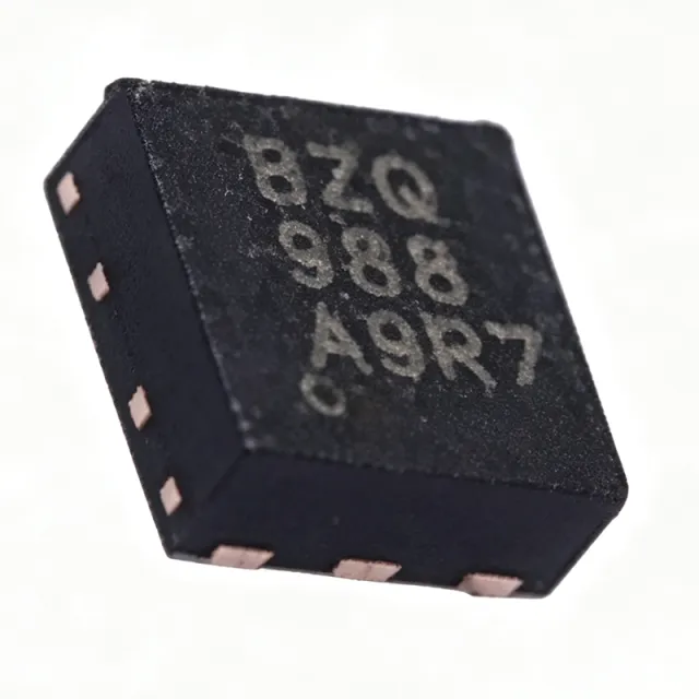
TPS61160DRVR - Boost White LED Driver 18V | Texas Instruments
The Texas Instruments TPS61160DRVR is a white LED driver boost converter with digital and PWM brightness control, delivering up to 10 series LEDs from a 2.7 V to 18 V input, with a 40-V rated integrated switch FET and 700 mA switch current limit in a 2-mm x 2-mm 6-pin WSON (DRV) package. An LED boost driver is a switching regulator (part of the DC-DC converter family of power management ICs) that steps a lower input voltage up to the higher voltage needed by a series LED string. Because LED brightness is proportional to forward current rather than voltage, boost LED drivers such as the TPS61160 regulate current through the string via a low-side sense resistor, providing constant-current operation independent of LED forward-voltage variation. Key features include a 600 kHz fixed switching frequency that shrinks the external inductor and capacitors, 26 V open-LED protection that clamps output overvoltage if the LED string fails open, and a 200 mV current-sense feedback reference that minimizes sense-resistor power loss and improves efficiency. Maximum duty cycle is 93%, supporting high step-up ratios. Technically, the integrated 40-V power MOSFET eliminates an external switch FET, cutting BOM count and layout area. Brightness control is flexible: apply a direct PWM signal, or use the single-wire digital interface that accepts PWM on the CTRL pin for stepless dimming without a dedicated MCU PWM output. Typical applications are LCD backlighting for smartphones, tablets, and portable navigation devices, plus general constant-current LED illumination powered by single-cell Li-ion or multi-cell alkaline/NiMH batteries. Design consideration: the 26 V open-LED protection clamp of the TPS61160 (38 V on the TPS61161) sets the maximum LED string voltage; verify the worst-case summed LED forward voltage stays safely below the clamp over temperature. Pricing cited as of 2026-09-01. This page synthesizes distributor pricing, drop-in alternatives, and practical design notes not found in the manufacturer datasheet.

TPS61165DBVR - 1.2A White LED Boost Driver, SOT-23-6 | TI
The Texas Instruments TPS61165DBVR is a high-brightness white LED driver housed in a 6-pin SOT-23 (DBV) package, integrating a 40-V-rated switch FET with a 1.2-A current limit. It operates over a 3-V to 18-V input range and uses a 1.2-MHz fixed-frequency PWM boost topology to drive series-connected LEDs. Reference voltage accuracy is specified at 2% with 200 mV typical, enabling tight LED current regulation via an external sense resistor. A boost converter (also called a step-up converter) is a switch-mode DC-DC converter that produces an output voltage higher than its input. Boost converters belong to the switching regulator family (alongside buck, buck-boost, SEPIC, and flyback topologies), which in turn falls under the broader category of voltage regulators within power management ICs. For LED driving, the boost topology is preferred when the LED string forward voltage exceeds the input supply - a common situation when powering white LEDs from a single-cell Li-ion battery or a 3.3-V/5-V rail. Key features include a built-in 38-V open-LED protection circuit, flexible 1-wire EasyScale digital brightness control, and PWM dimming capability. The 1.2-MHz switching frequency enables the use of small external inductors and ceramic capacitors, while the internal switch removes the need for an external FET. The SOT-23-6 package measures approximately 2.9 mm x 1.6 mm, making the IC suitable for space-limited handheld designs. The TPS61165DBVR uses peak-current-mode control with internal compensation, simplifying the external component selection to one inductor, input/output capacitors, a feedback resistor, and a sense resistor. This architecture balances regulation accuracy against BOM size, and the high switching frequency minimizes output ripple on the LED current. Load-disconnect during shutdown prevents leakage current through the LED string when the IC is disabled. Typical applications include single-cell Li-ion powered LED flash, smartphone backlight drivers, portable medical illumination, and industrial indicator panels. The wide VIN range also supports 9-V, 12-V, and 15-V bus systems, where the boost converter delivers tens of volts across multi-LED strings. For flash applications, the high switch current limit supports short-duration high-current pulses. When designing with this part, derate the inductor saturation current to at least 1.5 A to handle peak inductor currents during PWM dimming transients. Place the input capacitor and feedback resistors close to the IC pins to minimize switching noise injection into the analog control loop. The open-LED protection engages at approximately 38 V across the SW node - ensure the output capacitor and rectifier ratings exceed this threshold. This page synthesizes distributor pricing, drop-in pin-compatible alternatives, and practical PCB design notes not consolidated in the TI datasheet, helping engineers shorten part selection and reduce time-to-prototype.

TPS61194PWPR - 4-Ch 100mA Low-EMI LED Driver | Texas Instruments
The Texas Instruments TPS61194PWPR is a low-EMI, high-performance four-channel LED driver with integrated DC-DC converter that supports both boost and SEPIC topologies, delivering up to 100 mA per channel in a 20-pin HTSSOP (PWP) package. The device operates from an input voltage range of 4.5 V to 40 V, with an internal switching frequency programmable from 300 kHz to 2.2 MHz, and integrates four high-precision current sinks that can be combined for higher drive current. According to the TI product page, the integrated DC-DC uses adaptive output voltage control based on LED current sink headroom, maximizing efficiency across a wide range of LED forward voltages. A four-channel LED driver is a power management IC that integrates a switching converter (boost or SEPIC) with multiple current-sink outputs. The converter stages up an input supply to the voltage required by the LED string, while the current sinks regulate individual LED strings with high accuracy. This category sits within the broader hierarchy of power management IC -> LED driver -> backlight driver -> display power, and is used wherever multiple LED strings must be driven with tightly matched brightness, such as in automotive clusters, industrial HMIs, and large LCD backlights. The TPS61194 is engineered specifically for low electromagnetic emissions, easing CISPR 25 / CISPR 32 compliance in automotive and industrial systems. Key features of the TPS61194PWPR include 4.5 V to 40 V wide VIN range, 100 mP / channel current capability with PWM dimming, integrated boost + SEPIC converter, 300 kHz to 2.2 MHz programmable switching frequency, and dedicated current-sink regulation. The HTSSOP-20 PowerPAD package provides a thermal resistance low enough to handle the internal converter losses, while the four parallel current sinks allow paralleling of strings for higher currents (up to 400 mP per device). The low-EMI architecture (with spread-spectrum option on the switching frequency) eliminates many of the input-filter trade-offs typical of high-power LED drivers. From an architectural perspective, the TPS61194 uses a peak-current-mode control boost/SEPIC converter with adaptive output voltage, which automatically tracks the minimum required VOUT to keep the current sinks in regulation. The internal current references are matched within approximately 1% channel-to-channel (per TI documentation), and PWM dimming is handled through a dedicated PWM input with a high-frequency gate signal passed directly to the MOSFETs in the current sinks. Compared to discrete solutions, the integration reduces BOM count by an inductor, a switching MOSFET, a sense resistor, and an external current mirror. Typical applications for the TPS61194PWPR include LCD backlighting for automotive infotainment displays, industrial HMI panels, RGB LED signage, and small to medium-size LED matrix panels. The wide VIN tolerance makes the part a natural fit for 12 V and 24 V nominal supplies where load-dump transients must be tolerated without brownout. When designing with the TPS61194, the most common pitfall is undersizing the output capacitor bank of the integrated boost converter - the adaptive VOUT control needs sufficient bulk capacitance to handle PWM dimming transitions without flicker. A second consideration is layout: the thermal pad on the HTSSOP-20 package must be soldered to a sufficiently large copper pour to keep junction temperature within the -40 C to +85 C operating range. This page synthesizes distributor pricing, drop-in alternatives, and practical design notes not found in the manufacturer datasheet.
TPS61194PWPRQ1 - 4-Ch 100mA Automotive LED Driver | TI
The Texas Instruments TPS61194PWPRQ1 is an automotive-grade, low-EMI, high-efficiency 4-channel LED driver with integrated DC-DC converter, supporting both boost and SEPIC topologies. It delivers up to 100 mA per channel across four high-precision current sinks that can be paralleled for higher current, and operates from 4.5 V to 40 V input to survive automotive stop/start, cold-crank, and load-dump transients. An LED driver with current sinks is a power-management IC that regulates current through LED strings rather than setting a fixed voltage; this keeps luminous intensity constant despite temperature-induced forward-voltage variations. The TPS61194PWPRQ1 sits in the LED-driver sub-category of power management ICs (hypernyms: LED driver -> lighting PMIC -> power management IC -> semiconductor), and is purpose-built for backlighting and accent-lighting rails inside vehicles. Key features include an adjustable switching frequency of 300 kHz to 2.2 MHz (sync input), spread-spectrum frequency modulation for EMI reduction, adaptive output voltage control driven by current-sink headroom, PWM dimming, and AEC-Q100 qualification. The device also integrates fault detection (open-LED, short-LED, thermal shutdown, and input under-voltage lockout) to meet automotive safety diagnostics. Typical applications include automotive infotainment display backlighting, instrument-cluster illumination, HUD projection, RGB ambient lighting, and small-to-medium TFT-LCD backlight drivers. The wide input range and SEPIC option allow the same part to drive LED strings whose forward voltage is either below or above the battery rail. When designing with the TPS61194PWPRQ1, place the input bypass capacitor and inductor as close to the SW pin as possible, keep the LED-current-setting resistors within 1% tolerance, and leave adequate copper area under the PowerPAD for thermal dissipation. Frequency selection should avoid the AM radio band (530 kHz to 1710 kHz) by using either below-band or above-band switching. This page synthesizes distributor pricing, AEC-Q100 drop-in alternatives, and practical EMI design notes not found in the manufacturer datasheet alone, helping automotive lighting engineers shorten the BOM-down and EMC-compliance cycle.