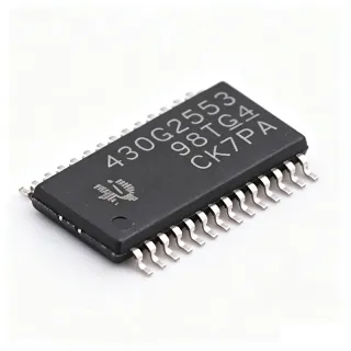
MSP430G2553IPW28 - 16MHz 16KB Flash MCU | Texas Instruments (Tape & Reel)
N.º da peça: MSP430G2553IPW28 ✓ Ativo| Qtd. | Preço unitário | Total |
|---|---|---|
| 1 | $0 | $0,00 |
| 10 | $0 | $0,00 |
| 100 | $0 | $0,00 |
| 500 | $0 | $0,00 |
| 1.000 | $0 | $0,00 |
MSP430G2553IPW28 Visão geral
A microcontroller (MCU) is a compact integrated circuit that governs a specific operation in an embedded system, containing a processor core, memory (Flash and SRAM), and programmable I/O peripherals. The MSP430 family sits within the broader hierarchy of 16-bit RISC microcontrollers under power-management-conscious embedded processing, and is renowned for five low-power modes (LPM0 to LPM4) that reduce current to as low as 0.1 uA in standby mode with RAM retention.
Key features include a 10-bit ADC, an analog comparator, two 16-bit timers, and a universal serial communication interface (USCI) supporting UART, SPI, and I2C. The device integrates a temperature sensor, brownout reset, and capacitive-touch-enabled I/O. Its internal DCO is factory-calibrated to 16 MHz with approximately 1% accuracy, often eliminating external crystals.
Architecturally, the MSP430G2553 uses a 16-bit RISC CPU with a von-Neumann memory map, enabling efficient code density and rapid wake-up from low-power modes. Firmware can be updated in-system via the two-wire Spy-Bi-Wire interface, simplifying production programming.
Typical applications include portable medical devices, wireless sensor nodes, smart meters, remote controls, and battery-powered consumer electronics. The 16KB Flash accommodates substantial application code, while 512B SRAM supports moderate buffering. The integrated comparator and ADC enable direct sensor interfacing, and the multiple communication interfaces allow easy connectivity to radios, displays, and other peripherals.
Design tip: place a 0.1 uF capacitor close to DVCC and 1 uF at the power entry; configure unused I/O as outputs to avoid floating-input leakage. This mature, widely available part has extensive community support for both prototyping and production. The MSP430G2553IPW28 is a popular choice for cost-sensitive, power-critical designs where performance and low energy consumption are paramount.
Alternativas drop-in para MSP430G2553IPW28 — mesmo encapsulamento, compatível pino a pino. Peças de encapsulamento diferente que exigem retrabalho na PCB são excluídas.
Ferramenta de comparação rápida — selecione peças alternativas para comparação lado a lado:
MSP430G2453IPW28R
✅ Drop-In ⚠️ Especificações não verificadas📋 Alternativa de referência (fora do catálogo)
MSP430G2253IPW28R
✅ Drop-In ⚠️ Especificações não verificadas📋 Alternativa de referência (fora do catálogo)
MSP430G2353IPW28R
✅ Drop-In ⚠️ Especificações não verificadas📋 Alternativa de referência (fora do catálogo)
MSP430G2553IPW28 Classificações máximas e características elétricas
| Core Processor | MSP430 CPU16 |
| Core Size | 16-Bit |
| Speed | 16 MHz |
| Program Memory Size | 16KB (16K x 8) |
| RAM Size | 512 x 8 |
| Number of I/O | 16 |
| Encapsulamento / Caixa | 28-TSSOP (0.173, 4.40mm Width) |
| Oscillator Type | Internal |
| Supply Voltage Range | 1.8V to 3.6V |
| Temperatura de operação | -40 C to +85 C |
| ADC Resolution | 10-bit |
| Timer Count | 2 x 16-bit |
| Communication Interfaces | UART, SPI, I2C |
| Low-Power Modes | 5 (LPM0 to LPM4) |
| Standby Current | 0.1 uA (Off Mode with RAM retention) |
| Brownout Reset | Yes |
| Temperature Sensor | Yes |
| Capacitive Touch I/O | Yes |
| DCO Accuracy | Approximately 1% (factory calibrated) |
| Packaging Type | Tape & Reel |
Configuração de pinos do MSP430G2553IPW28
| Pino 1 | P1.0 — General purpose I/O |
| Pino 2 | P1.1 — General purpose I/O |
| Pino 3 | P1.2 — General purpose I/O |
| Pino 4 | P1.3 — General purpose I/O |
| Pino 5 | P1.4 — General purpose I/O |
| Pino 6 | P1.5 — General purpose I/O |
| Pino 7 | P1.6 — General purpose I/O |
| Pino 8 | P1.7 — General purpose I/O |
| Pino 9 | P2.0 — General purpose I/O |
| Pino 10 | P2.1 — General purpose I/O |
| Pino 11 | P2.2 — General purpose I/O |
| Pino 12 | P2.3 — General purpose I/O |
| Pino 13 | P2.4 — General purpose I/O |
| Pino 14 | P2.5 — General purpose I/O |
| Pino 15 | P2.6 — General purpose I/O |
| Pino 16 | P2.7 — General purpose I/O |
| Pino 17 | VCC — Power supply input |
| Pino 18 | GND — Ground |
| Pino 19 | P3.0 — General purpose I/O |
| Pino 20 | P3.1 — General purpose I/O |
| Pino 21 | P3.2 — General purpose I/O |
| Pino 22 | P3.3 — General purpose I/O |
| Pino 23 | P3.4 — General purpose I/O |
| Pino 24 | P3.5 — General purpose I/O |
| Pino 25 | P3.6 — General purpose I/O |
| Pino 26 | P3.7 — General purpose I/O |
| Pino 27 | XIN — Crystal oscillator input |
| Pino 28 | XOUT — Crystal oscillator output |
Aplicações típicas
MSP430G2553IPW28 é adequado para 6 aplicaçãos: Portable Medical Devices, Wireless Sensor Networks, Smart Meters, Remote Controls, Battery-Powered Consumer Electronics, Industrial Sensors.
Portable Medical Devices
The MSP430G2553IPW28's ultra-low power consumption and integrated analog peripherals make it ideal for portable medical devices like glucose monitors and heart rate trackers. Operating from 1.8V to 3.6V, it can run on a single coin cell for years. The 10-bit ADC and comparator allow direct interfacing with biomedical sensors, while the 16KB flash accommodates firmware for signal processing and data logging. In a typical application, the MCU samples sensor data, processes it, and communicates via UART to a display or wireless module, all while drawing less than 1 uA in standby, ensuring prolonged battery life.
Recomendado
Wireless Sensor Networks
For wireless sensor networks, the MSP430G2553IPW28 provides a low-power 16-bit MCU with 16KB flash and 512B SRAM, sufficient for sensing and transmitting data. Its USCI supports UART, SPI, and I2C, enabling easy integration with radio transceivers like the CC2500. The device's five low-power modes ensure minimal energy consumption, critical for battery-operated nodes. In a typical design, the MCU sleeps most of the time, wakes periodically to read sensors, and sends data over the radio, efficiently utilizing the small SRAM for buffering. This configuration achieves multi-year battery life in environments like smart agriculture or industrial monitoring.
Recomendado
Smart Meters
Smart meters require a reliable MCU with ample memory and low power. The MSP430G2553IPW28 is an excellent choice, offering 16KB flash for complex metering algorithms and 512B SRAM for temporary data. Its integrated analog comparator can detect tampering, and the 10-bit ADC monitors voltage and current. The device operates from 1.8V to 3.6V, compatible with typical metering power supplies. In a smart meter, the MCU processes measurement data, communicates via UART to a communication module, and maintains timekeeping using a low-power timer, all while consuming minimal power to meet stringent regulatory requirements.
Recomendado
Remote Controls
For remote control applications, the MSP430G2553IPW28 offers a cost-effective solution with ultra-low power consumption. Its 16MHz CPU ensures quick response to button presses, while the 16KB flash stores complex encoding sequences. The MCU can interface with IR transmitters or RF modules via SPI or UART. With a standby current of 0.1 uA, the device can last years on a single battery. The internal DCO oscillator eliminates the need for an external crystal, reducing BOM cost and board space. In a typical remote, the MCU wakes from low-power mode on button press, encodes the command, and transmits, then returns to sleep, maximizing battery life.
Recomendado
Battery-Powered Consumer Electronics
Battery-powered consumer electronics, such as fitness trackers and smart watches, benefit from the MSP430G2553IPW28's ultra-low-power operation and small footprint. With 16KB flash and 512B SRAM, it can handle user interface logic, sensor data processing, and Bluetooth communication via a companion module. The device's 10-bit ADC and comparator enable noise-free sensor readings, while its multiple low-power modes allow the device to run on a button cell for months. The MCU's 1.8V to 3.6V supply range ensures compatibility with various battery chemistries, and its internal oscillator reduces component count. This makes the MSP430G2553IPW28 an ideal choice for compact, power-sensitive consumer gadgets.
Recomendado
Industrial Sensors
In industrial sensor applications, the MSP430G2553IPW28 provides robust performance with its 16MHz CPU and integrated peripherals. Its 10-bit ADC can digitize analog signals from pressure or temperature sensors, while the comparator enables threshold alarms. The device supports UART, SPI, and I2C, facilitating communication with PLCs or industrial networks. Operating from -40 to +85 C, it withstands harsh environments. With 16KB flash, it can store calibration data and communication protocols. Its low-power modes reduce energy consumption in battery-powered industrial sensors, making it a reliable choice for process control and monitoring systems that require long-term, maintenance-free operation.
Recomendado
Resumo dos produtos recomendados
Dados de referência de engenharia para MSP430G2553IPW28 — comparação, orientação de projeto e informações de conformidade.
Guia de seleção
Comparação com alternativas
| Parâmetro | Este produto | MSP430G2453IPW28R | MSP430G2253IPW28R | MSP430G2353IPW28R |
|---|---|---|---|---|
| Package | 28-TSSOP (PW) | 28-TSSOP (PW) | 28-TSSOP (PW) | 28-TSSOP (PW) |
| Brand | Texas Instruments | Texas Instruments | Texas Instruments | Texas Instruments |
| Flash Memory | 16KB | 8KB | 8KB | 8KB |
| SRAM | 512B | 512B | 256B | 256B |
| CPU Speed | 16 MHz | 16 MHz | 16 MHz | 16 MHz |
| ADC Resolution | 10-bit | 10-bit | 10-bit | 10-bit |
| Communication Interfaces | UART, SPI, I2C | UART, SPI, I2C | UART, SPI, I2C | UART, SPI, I2C |
| Operating Temperature | -40 to +85 C | -40 to +85 C | -40 to +85 C | -40 to +85 C |
Principais diferenciais
- Largest flash in the MSP430G2x53 TSSOP-28 family (vs MSP430G2453IPW28R)
- Higher SRAM capacity (vs MSP430G2253IPW28R)
- Integrated comparator and temperature sensor (vs MSP430G2353IPW28R)
Notas de projeto
Estimated: The MSP430G2553IPW28 draws about 230 uA in active mode at 1 MHz and 0.1 uA in off mode with RAM retention. When designing battery-powered systems, use the low-power modes effectively. Place a 0.1 uF ceramic capacitor as close as possible to the DVCC pin and a 1 uF capacitor at the power entry to filter noise. Ensure the supply voltage stays within 1.8V to 3.6V to avoid unreliable operation.
For best performance, keep the crystal oscillator components (if used) close to XIN and XOUT pins, and use short traces. Since the internal DCO is factory-calibrated, external crystals are optional. Route high-frequency signals away from analog input pins to reduce noise. Use a solid ground plane and place decoupling capacitors as recommended in the datasheet layout guidelines.
Configure unused I/O pins as outputs to prevent floating inputs that increase current consumption. When using the ADC, ensure the reference voltage is stable and the sampling time is adequate. Be aware that the brownout reset circuit may cause unexpected resets if the supply dips below the threshold; use a proper reset supervisor if needed. Always verify that the firmware fits within the 16KB flash and 512B SRAM constraints.
Informações de conformidade
Compliance information not provided in the verified data. Typically, TI MSP430 devices are RoHS compliant, but this should be confirmed with the manufacturer.