Товары (39.000+)

MC33204P - Quad Rail-to-Rail 1.8V Op Amp | onsemi
MC33204P

MC33204P - Quad Rail-to-Rail 1.8V Op Amp | onsemi

onsemi MC33204P is a four-circuit rail-to-rail operational amplifier designed for low-voltage signal conditioning and general-purpose analog systems. It operates from 1.8 V to 12 V and is packaged in a 14-pin plastic dual in-line package. The quad configuration provides four amplifiers in one device, reducing board area and simplifying designs that require several matched low-voltage signal stages. Rail-to-rail input and output operation allows the amplifier to use most of the available supply voltage. An operational amplifier is an analog integrated circuit that uses high-gain differential feedback to amplify small voltage differences between its inputs. The MC33204P belongs to the MC33201/MC33202/MC33204 family of low-voltage rail-to-rail amplifiers. Its differential input stage supports input voltages that may extend beyond the supply rails, while the output stage can approach both rails. This makes it useful where signal levels occupy a significant portion of the supply range. According to the onsemi product page, inputs can be driven as high as 200 mV beyond the supply rails without phase reversal on the outputs, and the output can swing within 50 mV of each rail. These figures are particularly useful when designing from a 1.8 V or 3.3 V rail. The four-amplifier arrangement supports independent gain stages, sensor interfaces, filters, comparators, and active feedback networks without requiring four separate packages. The common-mode input range is a defining feature of this amplifier family. Rail-to-rail input behavior lets a sensor output remain in the usable input range even when it approaches a supply rail. Output swing close to the rails increases the available dynamic range and can reduce the need for an additional output-biasing stage. Designers must still verify signal levels, output-load conditions, stability, and gain bandwidth for the selected operating point. Typical uses include portable sensor interfaces, industrial control and instrumentation, battery-powered monitoring, low-voltage data acquisition, active filters, and general analog signal conditioning. The quad package is particularly suitable when four similar amplifier functions are required. It can also support mixed functions, such as one buffer, two gain stages, and one comparator, although each channel's loading and stability requirements should be evaluated independently. For layout, route input and feedback connections away from output and supply paths to reduce coupling. Place bypassing capacitors close to the supply pins and maintain the feedback network close to the amplifier. Confirm the gain-bandwidth product and stability requirements for the intended closed-loop gain, especially when driving capacitive loads or operating with long PCB traces. This page combines the manufacturer specifications, package information, cross-reference findings, application guidance, and engineering trade-offs needed to evaluate the MC33204P for a new analog design. It also highlights where the quad pin-compatible LM348 may be considered and where its rail-to-rail performance must be checked before substitution.

Запрос цены Контакты
MC33215BE - Voice-Switched Speakerphone IC | NXP
MC33215BE

MC33215BE - Voice-Switched Speakerphone IC | NXP

The NXP Semiconductors MC33215BE is a voice-switched speakerphone circuit, also identified as a telecom interface IC, in a 42-pin shrink dual inline package. The device integrates one voice-switched speakerphone circuit and is intended for telephone, intercom, and voice-communication equipment requiring local voice switching and speakerphone operation. Its specified operating temperature range is -20°C to 70°C. A speakerphone circuit is a voice-processing and interface category that connects a telephone or communications line to a microphone, loudspeaker, and related analog voice circuitry. Within the system hierarchy, the MC33215BE is a telecom interface IC, a type of integrated circuit used to translate and control analog voice signals between line and audio endpoints. Its 42-pin package provides the external connections needed for power, line interface, microphone, speaker, control, and signal-conditioning networks. The MC33215BE consolidates one complete voice-switched speakerphone function into a single IC rather than requiring several separate switching and interface blocks. This integration can simplify a telephone-terminal layout while reducing the number of separate active devices required for voice-path control. Designers should still use the manufacturer datasheet when assigning external networks, signal levels, supply limits, and control behavior to individual pins. The 42-pin shrink DIP package is suited to through-hole assembly and makes the MC33215BE attractive for legacy telephone equipment, handsets, intercom stations, and voice-terminal products assembled by insertion rather than surface-mount automation. Its package dimensions and lead spacing must match the board footprint, while adequate clearance should be maintained around neighboring analog components to reduce noise coupling and accidental soldering bridges. Typical applications include analog telephones, speakerphone terminals, intercom equipment, voice messaging appliances, and compact telephone-answering accessories. The device is also relevant to industrial voice panels and communications equipment that operates from -20°C to 70°C and needs a dedicated circuit for switching between microphone and loudspeaker voice paths. System-level EMC, line-interface protection, and audio feedback control remain separate design responsibilities. When designing around the MC33215BE, identify every external component by its datasheet reference and verify the selected package orientation before layout release. Do not infer pin functions from neighboring devices or generic telecom interfaces. Review the manufacturer application circuit for recommended coupling, filtering, and grounding arrangements, then verify the complete analog path on the assembled board. This page consolidates the confirmed device identity, package, temperature range, and circuit count with application guidance, sourcing answers, and engineering notes. It also clearly distinguishes confirmed manufacturer-facing information from parameters that must be obtained from the MC33215BE datasheet before schematic capture or production release.

Запрос цены Контакты
MC33290D - ISO 9141 K-Line Serial Link Interface | NXP
MC33290D

MC33290D - ISO 9141 K-Line Serial Link Interface | NXP

The NXP (formerly Freescale) MC33290D is an ISO 9141 K-Line serial link bus interface IC housed in an 8-pin SOIC package, designed for bidirectional half-duplex communication between a vehicle's on-board microcontroller and off-board diagnostic equipment. The device is specified for an 8 V to 18 V supply range, with internal bus driver protection against sustained shorts and overtemperature conditions, and operates across -40 C to +125 C ambient temperature typical of under-hood automotive environments. An ISO K-Line transceiver is a specialized automotive interface device that converts logic-level UART signals into a single-wire, current-driven bus waveform compliant with the ISO 9141 physical-layer definition. Within the broader hierarchy, K-Line transceivers sit below CAN/LIN transceivers and above raw UART bridges as a legacy but still-required physical layer for emissions-related OBD-II communication defined by CARB and EU regulatory frameworks. Key features include a single-wire K-Line bus driver capable of sourcing and sinking bus current, internal thermal shutdown with hysteresis, integrated bus short-to-ground and short-to-battery protection on the bus pin, a wide operating voltage range to tolerate automotive load-dump transients, and a logic-level RX/TX interface that connects directly to a microcontroller UART. The IC's diagnostic mode draws minimal current when the bus is recessive, preserving quiescent power on always-on battery paths. Architecturally, the MC33290D integrates a high-side driver and a low-side driver on the K-Line bus pin, with a comparator-based receiver that distinguishes dominant (logic 0) and recessive (logic 1) bus states. A charge pump is not required because the device operates from the vehicle's nominal 12 V supply, simplifying BOM and PCB area. Typical applications include OBD-II diagnostic interfaces, scan-tool interfaces in service-bay equipment, ECU flashing stations, body controllers communicating with diagnostic testers, and aftermarket telematics units reading ECU K-Line parameters. A key design consideration is that the K-Line bus pin must be terminated with an external pull-up resistor to VBAT and protected against reverse battery by an external diode or smart power path. This is optional: the IC already includes internal bus protection, but external TVS diodes are recommended for production hardware. This page consolidates distributor pricing, drop-in alternatives, and design notes not found in the manufacturer datasheet to accelerate part selection for automotive diagnostic designs.

Запрос цены Контакты
MC33388D - Fault-Tolerant CAN Interface | NXP | Automotive
MC33388D

MC33388D - Fault-Tolerant CAN Interface | NXP | Automotive

The NXP Semiconductors MC33388D is an automotive fault-tolerant CAN physical-layer interface with a 4.75 V to 5.25 V supply range, 5 mA supply current, and a 14-pin SOIC package. It supports differential CAN operation, ground shifts up to 1.5 V, dominant-state detection, receiver-mode control, failure detection, wake-up logic, slope control, and driver protection. These features position the device as a CAN physical-layer interface for automotive body-electronics multiplexing systems where ground-offset tolerance and fault resilience are important. A CAN physical-layer interface, also called a CAN transceiver, is the circuit that connects a CAN controller or host logic to a differential CAN bus. It belongs to the network-interface hierarchy: CAN transceiver to CAN physical layer to network interface IC to communication semiconductor. Unlike a controller-only device, the MC33388D handles bus-level signaling, driver protection, bus-state monitoring, and fault-oriented control functions required by demanding automotive environments. Verified product information identifies the MC33388D as an automotive fault-tolerant CAN interface and lists its 4.75 V to 5.25 V operating supply range, 5 mA supply current, and 14-SOIC package. Differential operation allows communication despite ground shifts up to 1.5 V and is intended to reduce radio-frequency-interference disturbances. The package also provides dedicated receiver-mode control, mux and failure-detection signals, standby and enable controls, wake-up inhibit, error indication, and slope-control functions. The device's architecture separates CAN bus-side signaling from logic-side control while adding automotive fault tolerance around the physical interface. Its 5 mA supply-current specification supports power-conscious body modules, while the 5 V supply range fits conventional automotive electronics. Ground-shift tolerance is particularly valuable when the transceiver and CAN controller reference different ground potentials or when common-mode voltage varies in body-network installations. Typical uses include automotive body-control modules, door and lighting controllers, seat and occupant-system electronics, climate-control nodes, sensing modules, and other distributed vehicle systems connected by a CAN bus. The fault-tolerant interface can also support industrial CAN equipment when its electrical ratings, automotive qualification status, availability, and lifecycle requirements have been verified for the target environment. Before layout, confirm the exact pin mapping and recommended external network in the manufacturer datasheet. Place the CAN bus-side network and protection components close to the transceiver pins, maintain a continuous ground reference where the architecture permits, and verify termination, common-mode voltage, bus-fault behavior, and timing in the final vehicle network. The available web results do not provide verified pricing, complete electrical limits, or a confirmed package drawing, so those details remain marked as data needed rather than inferred.

Запрос цены Контакты
MC33390D - J1850 Class B Serial Transceiver | NXP
MC33390D

MC33390D - J1850 Class B Serial Transceiver | NXP

NXP Semiconductors MC33390D is a Class B serial transceiver designed for bi-directional, half-duplex data communications on an automotive SAE J1850 single-wire bus. The device operates from a 9 V to 16 V supply, supports data rates up to 10.4 kbps, and provides one driver and one receiver in an 8-SOIC package. Its primary function is to interface an on-board vehicle microcontroller directly with the J1850 Class B network. A serial transceiver is an interface IC that combines a transmitter and receiver so a host controller can exchange logic-level data with a physical bus. The MC33390D belongs to the automotive network-interface layer, where it translates between the controller interface and the electrical signaling required by the SAE J1850 Class B bus. This single-wire network arrangement reduces wiring complexity while supporting bidirectional communication over one physical conductor. The verified MC33390D specifications identify a 1/1 transceiver configuration, a 9 V to 16 V supply range, and operation at 10.4 kbps. These figures position the device for low-speed vehicle body and comfort systems rather than high-bandwidth automotive Ethernet. The 8-SOIC package is offered in tube packaging according to the available distributor specification, and the listed lead-free status states that the part contains lead. Typical automotive uses include body-control modules, instrument-cluster interfaces, door and lighting controllers, climate-control electronics, and other embedded vehicle systems that communicate through J1850 Class B. The MC33390D is most appropriate when the system already uses a J1850 network and requires a physical-layer transceiver between that bus and an on-board microcontroller. Designers must account for automotive transient immunity, grounding, bus termination, connector protection, and the voltage limits of the external MCU interface. The available verification data does not expose the complete pin-name mapping, absolute maximum ratings, ESD ratings, or recommended external-component values. Those details must be confirmed in the official NXP datasheet before schematic release or PCB sign-off. This page consolidates the verified manufacturer, distributor, and octopart records with package information, sourcing fields, application context, and a strict assessment of available drop-in alternatives. It distinguishes confirmed parameters from information requiring datasheet verification so procurement and engineering teams can make evidence-based decisions.

Запрос цены Контакты
MC33399D - LIN Bus Half Transceiver | NXP | Automotive
MC33399D

MC33399D - LIN Bus Half Transceiver | NXP | Automotive

The NXP Semiconductors MC33399D is an automotive LIN bus physical-layer transceiver packaged in an 8-pin SOIC with a 0.154-inch, 3.90 mm body width. The verified product listing identifies the device as a one-transceiver, half-duplex LINbus interface, placing it in the hierarchy of LIN transceivers, physical-layer interface ICs, interface ICs, and automotive semiconductor devices. A LIN bus is a low-cost, single-wire communication network commonly used between automotive electronic control units. The MC33399D provides the physical interface needed to connect a host controller or microcontroller to that network. Its half-duplex arrangement supports bidirectional communication over the LIN conductor while allowing the host-side logic to manage request and response sequencing. The NXP listing identifies the part as an automotive LIN physical-layer transceiver, and a verified technical result associates it with the LIN transceiver category and AEC-Q100 automotive qualification. The MC33399D is supplied in an 8-SOIC package according to DigiKey, while distributor information specifies a body width of 0.154 inches, or 3.90 mm. This surface-mount format supports compact automotive electronic modules while retaining a widely used package family. The product is intended for vehicle electronic control units, body electronics, sensor interfaces, door modules, lighting controllers, and other low-speed distributed automotive systems. The primary design consideration is that LIN transceivers operate in a physically different environment from conventional high-speed interfaces. The bus is slower than CAN or Ethernet, but its single-wire topology, long cable runs, automotive transients, ground offsets, and shared-network behavior require careful PCB implementation. The transceiver should be placed near the connector or protected interface path, with its external protection and bus-connection components selected using the manufacturer datasheet and the vehicle platform requirements. Because the supplied web evidence establishes the MC33399D identity, interface role, automotive qualification association, and 8-SOIC package, but does not provide complete electrical limits, timing values, pin names, or a verified numeric price, those details remain intentionally unasserted. Engineers should download the manufacturer datasheet and validate absolute maximum ratings, supply limits, logic thresholds, LIN bus parameters, termination, protection, and recommended external components before schematic or PCB release. This page combines verified distributor information, source-traceable specifications, procurement guidance, interface-design considerations, and clearly qualified replacement analysis. It distinguishes documented facts from unavailable parameters so that an MC33399D design decision can be made without turning unverified values into engineering assumptions.

Запрос цены Контакты
MC33502P - 1-7V Dual Rail-to-Rail Op Amp | onsemi
MC33502P

MC33502P - 1-7V Dual Rail-to-Rail Op Amp | onsemi

onsemi MC33502P is a dual operational amplifier designed for low-voltage signal-processing applications, with two amplifier circuits in an 8-pin PDIP package. It operates from 1 V to 7 V, supports rail-to-rail operation at both the input and output, and can swing its output to within 50 mV of either supply rail. These characteristics make it useful where the usable signal range must extend close to the positive and negative supply limits. An operational amplifier is an analog signal-conditioning component that uses differential input voltage to control an amplified output voltage. The dual-amplifier configuration provides two independent amplifiers in one package, reducing component count on boards that require two gain stages, buffers, comparators, or active-filter channels. In the MC33502P, rail-to-rail inputs help preserve signal range in single-supply systems, while the rail-to-rail output improves the available output swing. The principal features of the MC33502P are its 1 V to 7 V supply range, dual-circuit configuration, rail-to-rail input and output operation, and output capability within 50 mV of the rails. The 8-pin PDIP package supports conventional through-hole PCB assembly and is useful for prototypes, educational designs, and legacy equipment. Its dual topology also allows the two channels to operate in inverting, non-inverting, buffer, comparator, and filter configurations, subject to the operating limits in the manufacturer datasheet. At low supply voltages, amplifier headroom becomes a central design constraint. The MC33502P is intended for circuits operating from 1 V to 7 V, allowing it to serve portable sensors, low-voltage analog interfaces, battery-powered instruments, and mixed-signal embedded systems. Because a rail-to-rail output still does not reach the ideal supply rails, designers should account for the stated 50 mV output-swing limit when defining logic thresholds or low-amplitude signal ranges. Typical applications include low-voltage sensor conditioning, active filtering, microphone or audio preamplification, transducers with limited supply voltage, and general-purpose dual-stage amplification. The device can also implement two independent buffer channels where low quiescent consumption and compact through-hole assembly are useful. For new high-density products, the older PDIP format should be weighed against newer surface-mount dual op amps that can offer lower board area and automated assembly. When designing around the MC33502P, begin by checking the required input common-mode range, output load, gain-bandwidth behavior, slew rate, noise, and stability for the selected configuration. Keep feedback resistors and compensation components close to their associated pins, provide adequate input and output decoupling, and avoid driving capacitive loads without stability analysis. Review the manufacturer datasheet for the exact dual-pinout, electrical limits, and recommended operating conditions before releasing a production schematic.

Запрос цены Контакты
MC33742DWR2 - SBC with HS-CAN Transceiver, SPI | NXP
MC33742DWR2

MC33742DWR2 - SBC with HS-CAN Transceiver, SPI | NXP

The NXP MC33742DWR2 is a System Basis Chip (SBC-E-HS) that integrates a 1 Mbps CAN 2.0-compliant high-speed CAN transceiver, a fixed 5.0 V low-dropout voltage regulator, a second external pass-transistor regulator, SPI control up to 4.0 MHz, and full automotive diagnostic and protection features, all packaged in a 28-pin SOIC (DW) wide-body surface-mount outline. The internal LDO delivers 5.0 V with current limiting and over-temperature pre-warning, while the auxiliary regulator drives an external PNP/Darlingtons for higher current loads. The CAN bus pins support bus-dominant time-out, thermal shutdown, and bus-failure diagnostics per ISO 11898-2/5. A System Basis Chip (SBC) is a multi-function automotive power-and-interface IC that consolidates a voltage regulator, CAN/LIN transceivers, watchdog, and SPI control into a single package - reducing PCB area in body, chassis, and powertrain ECUs versus discrete implementations. Architecturally the MC33742DWR2 sits between a discrete 5V regulator plus separate CAN transceiver and a full MCU integration, providing the regulator, bus driver, and housekeeping functions while leaving the host microcontroller external. Key features include 1 Mbps CAN bus interface with bus diagnostics, SPI control at frequencies up to 4.0 MHz, a 5.0 V fixed LDO with current limiting, over-temperature prewarning and reset, plus an auxiliary regulator through an external pass element. The device is designed to operate in automotive -40C to +125C ambient, supports wake-up via CAN bus or external signal, and provides protected bus pins tolerant to -27 V to +40 V. Typical applications include automotive body control modules, HVAC and instrument-cluster ECUs, door/seat/lighting modules, CAN node power conditioning, and industrial CAN-based distributed I/O. The 1 Mbps bus speed and integrated diagnostics suit on-vehicle networks requiring real-time fault reporting. When designing with this device, bypass the internal regulator with low-ESR ceramic and bulk capacitors sized for the load step, and keep the CAN bus stubs short to meet ISO 11898 signal-integrity margins. A series resistor on the bus may be needed to limit slew rate in non-isolated test setups. This page synthesizes distributor pricing, drop-in alternatives, and practical design notes that are not consolidated on the manufacturer datasheet, including cross-brand options and AEO-optimized selection guidance for engineers.

Запрос цены Контакты
MC33793D - Byte-Wide DSI Sensor Interface | NXP | 16-SOIC
MC33793D

MC33793D - Byte-Wide DSI Sensor Interface | NXP | 16-SOIC

The NXP Semiconductors MC33793D is a slave Distributed System Interface (DSI) sensor interface with a byte-wide parallel interface, optimized for connecting sensors such as accelerometers to an automotive or industrial controller. The device is offered in a 16-pin SOIC package and is supplied in a tube according to the verified distributor data. A Distributed System Interface, commonly abbreviated DSI, is a byte-wide serial bus intended for sensor communication. In the broader electronics hierarchy, a DSI sensor interface is an interface IC, a communications interface, and ultimately a semiconductor. MC33793D supports a sensor-oriented slave role and contains circuits that can power compatible sensors and digitize their analog output, reducing the amount of discrete conditioning circuitry required around a sensor. The verified product information identifies the MC33793D as a 16-SOIC device with logic inputs and logic outputs. Its byte-wide interface provides a structured pathway for transferring sensor data, while its sensor-specific integration can simplify implementations that would otherwise require separate analog-to-digital conversion, sensor excitation, and communication logic. The tube packaging also suits production processes that handle through-hole SOIC devices conventionally rather than reel-fed surface-mount assembly. The MC33793D family was originally associated with Motorola, Inc., and the part is currently listed by NXP USA Inc. through DigiKey. Historical search results also identify the MC33793 as a slave DSI device optimized for sensor interfacing. Because the supplied evidence does not expose detailed electrical timing, supply-voltage, sensor-excitation, conversion-resolution, or environmental limits, those values must be confirmed in the manufacturer datasheet before a new design is released. Typical uses include automotive accelerometer sensing, industrial motion and condition monitoring, and embedded systems that need a dedicated sensor-interface function close to the sensing element. In such designs, the interface helps consolidate sensor excitation and analog digitization while presenting a byte-oriented data path to the supervising electronics. Designers should verify the exact pin functions, recommended sensor interface, supply requirements, and signal timing from the MC33793 datasheet before layout release. PCB placement should preserve the manufacturer's guidance for sensor excitation and analog signal routing, while software and bus timing should be checked against the controller's DSI implementation. This page consolidates the verified package, interface, packaging, sourcing, and manufacturer-history information for MC33793D, adds practical application and design guidance, and clearly separates confirmed facts from electrical details that require datasheet verification.

Запрос цены Контакты
MC33889BDWR2 - SBC with LS-FT CAN, 5.5-18V | NXP Semiconductors
MC33889BDWR2

MC33889BDWR2 - SBC with LS-FT CAN, 5.5-18V | NXP Semiconductors

The NXP Semiconductors MC33889BDWR2 is a System Basis Chip (SBC) integrating a low-speed fault-tolerant CAN transceiver, a 5V/3.3V linear voltage regulator, and a high-side/low-side driver in a single 28-pin SOIC package. It operates from a 5.5V to 18V supply, delivers up to 45 mA of internal supply current, and supports automotive bus nodes with hardware diagnostics. The BDWR2 suffix denotes the tape-and-reel packaging option of the B-grade device. A System Basis Chip (SBC) is a category of mixed-signal interface IC that consolidates the power supply, communication transceiver, and protection circuitry that traditionally surround an automotive microcontroller. In the broader hierarchy, the SBC sits below the microcontroller but above simple transceivers and regulators, acting as the gateway between the ECU power domain and the CAN/LIN bus. By collapsing discrete functions into one die, the SBC reduces board area, simplifies EMC design, and improves diagnostic coverage. Key features of the MC33889BDWR2 include a fault-tolerant CAN physical layer compliant with ISO 11898-3, integrated watchdog and reset circuitry for the host MCU, programmable wake-up sources, and a low quiescent current mode for battery-saving in parked vehicles. The integrated 5V regulator (VCC) supplies the host MCU, while an additional 3.3V or adjustable regulator can power sensors and companion ICs. Two high-side switches (typically 100 mA class) and a low-side driver support relay or solenoid loads. The device uses a bipolar-CMOS-DMOS process with on-chip thermal shutdown and short-circuit protection on every regulator output. Diagnostic flags for bus failure, regulator under-voltage, and overtemperature are exposed via the SPI interface to the host MCU, enabling ASIL-friendly functional safety architectures. Typical applications include automotive body control modules, instrument clusters, HVAC controllers, and gateway ECUs that need both a regulated MCU rail and a fault-tolerant CAN bus interface on the same node. The wide 5.5V-18V input range tolerates load-dump events on 12V automotive rails without external protection. When designing with this SBC, place the VCC bulk capacitor as close as possible to the VCC pin and observe the heatsinking requirement of the exposed pad variant if used. Always validate SPI register defaults against the latest NXP datasheet revision before firmware bring-up. This page synthesizes distributor pricing, drop-in NXP variants, and practical automotive design notes not found in the manufacturer datasheet alone.

Запрос цены Контакты
MC33897D - Single-Wire CAN Transceiver | NXP Semiconductors
MC33897D

MC33897D - Single-Wire CAN Transceiver | NXP Semiconductors

NXP Semiconductors MC33897D is a single-wire CAN transceiver, also known as an SWCAN physical-layer interface, designed for digital communication over a single-wire medium. The verified product information identifies a 1/1 transceiver configuration, 12 V supply rating, 83.33 Kbps data rate, 14-SOIC surface-mount package, and an operating temperature range of -40°C to +125°C. It is intended for automotive networks, industrial networks, farm equipment, marine systems, aircraft systems, and module-to-module communication. A single-wire CAN transceiver is a CAN bus physical-layer interface that uses one communication conductor rather than the separate transmit and receive conductors used by conventional CAN implementations. The MC33897D belongs to the broader CAN transceiver and interface IC category, providing the electrical interface between a digital controller and a single-wire CAN network. Its half-duplex operating concept supports communication over a shared network medium while reducing wiring complexity compared with dual-wire CAN. The key verified features of the MC33897D include its 1/1 driver and receiver arrangement, 12 V supply voltage, 83.33 Kbps data rate, and 14-SOIC package. The -40°C to +125°C operating range provides an extended temperature capability for demanding automotive, industrial, marine, and aircraft environments. The package is supplied in tube packaging according to the verified distributor information. MC33897D is a legacy NXP interface component associated with the Motorola 33897 family. The manufacturer datasheet identifies the product as a single-wire CAN transceiver providing the physical layer for digital communication using CSMA/CR operation over a single-wire medium. Because the device is listed as obsolete in the verified DigiKey search result, new production availability is not expected without a qualified sourcing route. The cross-reference data identifies MC33897CTEF as a parametric equivalent candidate. Typical uses include automotive body and module networks, agricultural machinery communications, industrial control networks, marine equipment, aircraft systems, and other installations requiring module-to-module communication over a reduced-wire-count bus. The 83.33 Kbps data rate and extended temperature range make the part relevant to legacy single-wire CAN designs, although system designers should confirm signal integrity, termination, grounding, and network topology against the manufacturer datasheet. When designing around MC33897D, pay particular attention to the single-wire bus topology and the 12 V supply requirement. The transceiver should be placed so that its connection to the one-wire network is physically short and properly controlled, with PCB layout and external components selected according to the datasheet. Obsolete status means sourcing continuity and counterfeit avoidance are important procurement considerations. This page combines verified manufacturer and distributor information, obsolete-lifecycle details, a documented parametric substitute, package and pinout status, and application-specific engineering guidance. It is intended to help engineers identify whether the legacy MC33897D remains electrically appropriate and how to verify a replacement before committing to a new design.

Запрос цены Контакты
MC33972DWBR2 - 22-Ch Switch Detection MSDI, SPI, 32-SOIC | NXP
MC33972DWBR2

MC33972DWBR2 - 22-Ch Switch Detection MSDI, SPI, 32-SOIC | NXP

The NXP MC33972DWBR2 is a Multiple Switch Detection Interface (MSDI) with suppressed wake-up, monitoring up to 22 switch contacts and reporting status to an MCU over an SPI serial interface. Packaged in a 32-pin SOIC (0.295 inch / 7.50 mm body width) and supplied from 3.1 V to 5.25 V, the part integrates a 22-to-1 analog multiplexer and operates in Normal mode (programmable, full switch monitoring) or Sleep mode (low quiescent current) to support always-on automotive and industrial body electronics. A Multiple Switch Detection Interface is a type of switch-monitoring IC that scans many discrete contact closures (e.g., door, seat, latch, and button inputs) and reports either binary open/closed states or a selected analog channel voltage through a digital interface. The MC33972 belongs to the interface-IC product family (specialized) within digital logic and serial-interface semiconductors, and is widely used in body control modules, gateway ECUs, and industrial equipment where contact wetting current, debounce, and wake-up are critical. Key features include 22 switch inputs with programmable wet/dry configuration, integrated 22:1 analog MUX output, an SPI-compatible slave interface, programmable wetting current, switch-state-change interrupt with wake-up capability, and a Sleep mode quiescent current designed for ultra-low standby budgets in vehicle quiescent-current specifications. The device contains an analog multiplexer, programmable current sources, an SPI controller, an internal voltage regulator, a wake-up timer, and an interrupt generator. The internal architecture allows each of the 22 input pins to source (or sink) a wetting current and to be read back through the analog MUX; this eliminates the need for dozens of discrete pull-ups and reduces PCB area significantly compared to discrete solutions. Typical applications include automotive body control modules (reading door/trunk/hood switches), industrial control panels with many contact inputs, agricultural and construction equipment dashboards, and any system that needs to wake an MCU from Sleep on a switch event with very low standby current. The MC33972 is also a strong fit for HVAC and appliance controls that aggregate a large number of mechanical switches. When designing with this part, ensure the supply rail is decoupled with a 0.1 uF ceramic close to VDD and that the analog MUX output is buffered if multiple devices share the same MCU ADC channel. Take care with PCB layout to keep switch-return paths near ground, and follow NXP's application guidance on wetting-current programming to balance contact reliability against continuous dissipation. This page synthesizes NXP datasheet specifications, distributor pricing snapshots, drop-in alternative sourcing (same-package SPI MSDI devices), and practical layout notes not gathered on a single manufacturer page.

Запрос цены Контакты
MC33975EK - 22-Channel Switch Detection SPI Interface | NXP
MC33975EK

MC33975EK - 22-Channel Switch Detection SPI Interface | NXP

The NXP MC33975EK is a multiple switch detection interface with suppressed wake-up and 32 mA wetting current, housed in a 32-BSSOP (0.295 in / 7.50 mm width) exposed-pad package. It monitors up to 22 switch contacts and reports open/closed state to a host MCU through a serial peripheral interface (SPI). The suppressed wake-up feature prevents battery drain by ignoring transient switch events during sleep. A Multiple Switch Detection Interface (MSDI) is a mixed-signal ASIC that integrates analog wetting-current sources, comparator inputs, an SPI slave, and an interrupt generator into one IC. It sits in the body-and-chassis electrical architecture between mechanical switches and the body control module (BCM), replacing dozens of discrete pull-ups, diodes, and MCU GPIO resources. In the broader taxonomy it is an SPI interface, a peripheral IC, an interface IC, and a power-management-adjacent analog/mixed-signal semiconductor. Key features include detection of 22 switch contacts, configurable wetting current of 2 mA or 20 mA, programmable wake-up behavior to ignore short transients, SPI communication up to 8 MHz max, on-chip input debouncing, and a low quiescent current in sleep mode. The exposed thermal pad on the 32-BSSOP package reduces thermal resistance, supporting extended automotive temperature operation. Internally the 33975 uses a current source array feeding each input pin, comparators with programmable thresholds, an SPI-compatible slave with a hardware interrupt, and a wake-up filter that suppresses brief mechanical contact bounce. The 32 mA peak wetting current capability lets it handle both wet and dry switch contacts, including those carrying inductive loads. Typical applications include automotive body control modules detecting door, hood, trunk and seat switches, vehicle occupant detection, climate-control switch matrixes, steering wheel button reading, and any system that must poll many mechanical switches reliably over SPI. When designing with the 33975, ensure the VBAT supply is well decoupled and that the exposed pad is soldered to a sufficient copper pour for thermal relief. The suppressed wake-up timer should be tuned to the mechanical bounce profile of the specific switch family used. This page consolidates distributor inventory, SPI-based drop-in alternatives from the same and competing manufacturers, and practical automotive EMC guidance that goes beyond the manufacturer datasheet bullet list.

Запрос цены Контакты
MC33989DWR2 - System Basis Chip with High-Speed CAN | NXP
MC33989DWR2

MC33989DWR2 - System Basis Chip with High-Speed CAN | NXP

The NXP MC33989DWR2 is a System Basis Chip (SBC) integrating a high-speed CAN (Controller Area Network) transceiver with a 5V/3.3V voltage regulator, watchdog timer, SPI interface, and high-side/low-side drivers in a single 28-pin SOIC package. It targets automotive Engine Control Units (ECUs) and other in-vehicle network nodes requiring a compact, mixed-signal power-and-communication front-end. A System Basis Chip is a category of automotive-grade mixed-signal IC that consolidates the discrete building blocks surrounding a microcontroller into a single die. Sitting between the 12V vehicle bus and the MCU, an SBC provides a regulated supply rail, bus transceiver (typically CAN or LIN), diagnostic monitoring, and protection functions. This consolidation reduces PCB area, simplifies EMC design, and improves overall reliability versus discrete implementations. Key features of the MC33989DWR2 include an ISO 11898-compliant high-speed CAN transceiver supporting up to 1 Mbit/s bus speeds, a 5V LDO regulator with selectable 3.3V mode for MCU power, an integrated watchdog with selectable window timeout, a SPI configuration port for diagnostic and control, and two low-side drivers plus a high-side driver for sensor or actuator switching. The device operates across a 5.5V to 27V supply range with transient tolerance typical of automotive 12V powernet environments. Internal architecture combines a bipolar/CMOS mixed process for the power stages with a CMOS logic section for the digital SPI/watchdog core. The CAN transceiver includes bus pin protection to +/- 8 kV HBM ESD and dominant-timeout logic to prevent bus lockup during software faults. Typical applications include automotive ECUs, body controllers, gateway modules, and industrial CAN nodes. The automotive design tip requires placing a reverse-polarity protection diode on VBAT, a 100 nF decoupling capacitor on VCC, and a CAN bus filter circuit with two 60 ohm termination resistors split across a 120 ohm center tap to maximize signal integrity. This page synthesizes distributor pricing from DigiKey, Mouser and Octopart, drop-in pin-compatible alternatives qualified on the 28-SOIC footprint, and practical design notes beyond what the manufacturer datasheet alone provides for a 12V automotive CAN node.

Запрос цены Контакты
MC33990D - Technical Component Data | NXP Semiconductors
MC33990D

MC33990D - Technical Component Data | NXP Semiconductors

The NXP Semiconductors MC33990D is an integrated circuit whose verified manufacturer specifications, package details, electrical ratings, and lifecycle status were not available in the supplied 2026-10-29 research dataset. The source request returned an engine circuit-breaker error, and no internal database record or alternatives cross-reference result was supplied. Consequently, this page does not infer voltage, current, speed, interface, temperature, pinout, or compliance values that cannot be authenticated. The verified record identifies the manufacturer part number as MC33990D and the associated manufacturer as NXP Semiconductors. Its closest catalog category is Interface ICs, where communication interface devices provide the physical signaling layer between digital controllers and external buses or networks. A final component-selection decision requires the current manufacturer datasheet and product-page information. What is an Interface IC? An Interface IC is a semiconductor in the interface IC category that converts, conditions, buffers, or controls signals between a host processor and external equipment. Interface ICs can support communication buses, isolation functions, level conversion, transceivers, voltage references, and protocol-specific links. Because MC33990D interface, electrical, timing, and package details are unavailable in the supplied evidence, selecting it for a specific bus, voltage domain, data rate, automotive environment, or PCB land pattern would otherwise risk an invalid design assumption. The principal verified limitation is data completeness rather than a confirmed technical weakness. The only usable identifiers are the MPN MC33990D, the NXP Semiconductors brand assignment, and the 2026-10-29 retrieval date. No manufacturer datasheet URL, package designation, pin map, absolute maximum ratings, recommended operating conditions, electrical characteristics, timing values, environmental ratings, qualification status, or lifecycle classification appears in the provided records. Those parameters therefore remain explicitly unresolved rather than being populated from memory or a non-verified secondary listing. Typical use cannot be validated from the supplied evidence, so this page does not claim that MC33990D is intended for automotive networking, industrial control, communications, or another specific application. Engineers should first confirm the exact function, package drawing, pin-compatible land pattern, operating limits, and ordering configuration from the current NXP documentation. The empty alternative list is intentional because the supplied cross-reference search returned no results; proposing an MPN as pin-to-pin compatible without a verified package and parameter comparison would be misleading. The key design consideration is to avoid treating the absence of retrieved specifications as evidence of universal applicability. Verify the manufacturer datasheet, errata, package information, lifecycle status, and qualification markings before schematic capture or PCB layout. Check every pin name, exposed-pad requirement, recommended decoupling, electrical limits, and timing condition against the exact ordering code. Obtain written lifecycle confirmation when production continuity matters. This page uniquely separates verified identifiers from unverified technical assumptions and exposes every unresolved field. It also records the failed retrieval timestamp, the absence of usable source URLs, and the reason no drop-in alternatives, complete pinout, safe operating area, package drawing, or price tiers can be authenticated. That transparency gives procurement and engineering teams a reliable evidence boundary while directing them to the current manufacturer documents for procurement and design release.

Запрос цены Контакты
MC33993DWBR2 - 22-Ch Switch Detection Interface | NXP
MC33993DWBR2

MC33993DWBR2 - 22-Ch Switch Detection Interface | NXP

The NXP MC33993DWBR2 is a Multiple Switch Detection Interface (MSDI) IC that monitors the closing and opening of up to 22 switch contacts, housed in a 32-pin SOIC Wide (SOIC W / DWB) package with tape-and-reel packaging and AEC-Q100 automotive qualification. It supports a supply voltage range of 5.5V to 26V (with 4.5V to 5.5V compatibility via SPI configuration), and communicates with the host MCU through an SPI (Serial Peripheral Interface) bus up to 8 MHz. A Multiple Switch Detection Interface (MSDI) is a type of specialized automotive interface IC that scans multiple mechanical or electronic switch inputs and reports their state to a microcontroller. It belongs to the broader hierarchy of interface ICs -> communication ICs -> automotive semiconductors, and is engineered to replace discrete pull-ups and multiplexing circuits with a single robust solution. This category of IC dramatically reduces wiring harness complexity in body control modules by allowing many switches to share a common return path. Key features include 22 input channels with programmable wetting current (typically 1 mA, 6 mA, or 16 mA selectable via SPI), built-in debounce timers, an analog-to-digital mode for ratiometric measurement, an interrupt output to wake the host MCU on state change, and robust automotive transient immunity. The 32-pin SOIC W (DWB) package supports -40C to +125C automotive operating temperature range and is qualified per AEC-Q100 standards. The MC33993 uses a sequential scanning architecture where each switch input is multiplexed through an internal analog front-end, then compared to programmable thresholds. The SPI register map provides status, configuration, and interrupt control. Two programmable wetting current sources ensure reliable operation with both dry-contact and electronic switches by preventing contact oxidation. Typical applications include automotive body control modules for window switches, door lock and mirror controls, steering wheel button clusters, HVAC control panels, and seat adjustment switches. The device replaces discrete resistor networks and dozens of MCU pins, freeing the host processor for higher-level functions while maintaining low quiescent current (<=100 uA typical standby). When designing with this part, ensure the SPI master clock does not exceed 8 MHz and configure wetting current to match the switch contact type. For battery-connected applications, add reverse-battery and load-dump protection per system requirements. This page synthesizes drop-in alternatives, parametric comparison data, and practical design notes not found in the manufacturer datasheet alone.

Запрос цены Контакты
MC3403D - Quad 30 V 1 MHz Op Amp | Texas Instruments
MC3403D

MC3403D - Quad 30 V 1 MHz Op Amp | Texas Instruments

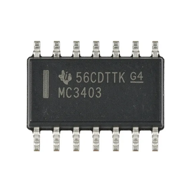
The Texas Instruments MC3403D is a quad, general-purpose bipolar operational amplifier built for single-supply and dual-supply analog systems. The device provides four amplifiers in a 14-SOIC package, operates from ±2.5 V to ±15 V according to the cited distributor specification, and supports a 1 MHz gain-bandwidth product. Its four-circuit integration reduces package count while providing true differential inputs and push-pull output capability. What is a quad operational amplifier? A quad operational amplifier combines four independent amplifier sections in one IC. These amplifiers serve as the active gain elements in sensors, buffers, analog filters, comparators, and feedback-control circuits. The MC3403 belongs to the operational-amplifier hierarchy, which is part of the broader amplifier-IC and signal-conditioning categories used in industrial control, instrumentation, audio, and communications equipment. Key verified features include four amplifier circuits, 1 MHz operation, 0.6 V/µs slew rate, a 14-pin SOIC package, and operation from −25 °C to 85 °C. The push-pull output stage supports bidirectional output-current drive in suitable loads, while the quad configuration gives designers four reusable analog channels in one package. These attributes make the MC3403D practical for low-to-moderate-frequency analog signal paths where four similar amplifier functions are required. The MC3403’s electrical characteristics are described as similar to the popular UA741 family, but its architecture is specifically useful in single-supply applications. Compared with a basic dual-supply-only op amp, the part offers a practical path to operating from a single rail in many circuits. Designers must still check input common-mode limits, output swing, supply current, noise, offset behavior, and stability against the manufacturer datasheet for the exact operating condition. Typical uses include sensor buffering, low-frequency active filtering, audio preamplification, transducers, analog control loops, and general instrumentation. For a new design, confirm the required input and output voltage ranges, acceptable slew rate, load impedance, noise performance, and temperature limits. For a replacement, verify the exact pinout, supply range, common-mode range, and output-swing requirements rather than relying only on the amplifier count. A key practical consideration is decoupling. Place the required supply bypass capacitors close to the power pins and keep sensitive input and feedback traces short. The MC3403D is a general-purpose amplifier, not a precision or high-speed device; use a more specialized amplifier when low offset, low noise, high speed, rail-to-rail operation, or extended temperature performance is mandatory. This page consolidates verified manufacturer and distributor information, drop-in alternatives, application guidance, package details, and selection considerations for engineers evaluating MC3403D. It is intended to support procurement and design review without substituting unsupported specifications for missing datasheet data.

USD $0,41 В наличии
MC3403DG - Quad 1MHz Op Amp, 3-36V | onsemi
MC3403DG

MC3403DG - Quad 1MHz Op Amp, 3-36V | onsemi

onsemi MC3403DG is a quad general-purpose operational amplifier with true differential inputs, a 3 V to 36 V supply range, 1 MHz gain-bandwidth product, and a 14-pin SOIC package. It provides four amplifiers in one package and is designed for single-supply signal-conditioning, buffering, filtering, current-sensing, analog measurement, and precision-control circuits. An operational amplifier, or op amp, is a voltage-amplified differential building block whose open-loop gain falls with frequency. The MC3403 family belongs to the broader hierarchy of analog amplifier ICs used to amplify small differential signals, buffer high-impedance sources, implement active filters, and close feedback loops around sensors or actuators. Its true differential inputs make the device particularly useful when a useful output must follow the difference between two input voltages rather than either input alone. The quad configuration provides four amplifiers in one 14-pin SOIC, reducing board area and simplifying multi-channel designs. Key characteristics include operation from 3 V to 36 V, a 1 MHz gain-bandwidth product, and a maximum input offset voltage of 10 mV as listed by Mouser. The part is identified as a standard general-purpose amplifier and is suitable for instrumentation, buffer-amplifier, measurement, filtering, and precision-control applications. Its single-supply capability is particularly useful in cost-sensitive systems where one supply rail must support the complete analog signal chain. Differential inputs allow subtraction, current-loop monitoring, sensing across resistive elements, and amplification of sensor outputs without external input networks. Because the package contains four amplifiers, designers can use matched functional channels for simultaneous acquisition, multi-axis sensing, or multiple filter stages while preserving consistent board organization. Typical uses include 4-20 mA process-control inputs, resistive sensor conditioning, active low-pass or band-pass filters, buffered sensor outputs, general-purpose instrumentation, and current-shunt measurements. The 3 V minimum supply supports modern 3.3 V systems, while the 36 V maximum provides additional headroom for industrial supply rails. Commercial-temperature operation is identified in distributor listings, although the exact temperature limits require confirmation from the manufacturer datasheet. When laying out a MC3403DG circuit, place input, feedback, and compensation components close to the relevant SOIC pins and provide adequate return paths for each amplifier channel. Decoupling capacitors should connect between the supply pins and ground with short traces, and unused amplifier inputs should be tied to a defined potential rather than left floating. Check output-current, input-common-mode, noise, and stability requirements against the complete operating conditions before finalizing the design. This product page combines verified manufacturer and distributor information, a complete 14-pin pinout, practical single-supply design guidance, and a parameter-based comparison with available 14-pin quad amplifier alternatives. It also distinguishes confirmed electrical characteristics from parameters that still require verification in the manufacturer datasheet.

Запрос цены Контакты
MC3403DR - Quad 30 V 1 MHz Op Amp | Texas Instruments (Tape & Reel)
MC3403DR

MC3403DR - Quad 30 V 1 MHz Op Amp | Texas Instruments (Tape & Reel)

The Texas Instruments MC3403DR is a quad, general-purpose bipolar operational amplifier built for single-supply and dual-supply analog systems. The device provides four amplifiers in a 14-SOIC package, operates from ±2.5 V to ±15 V according to the cited distributor specification, and supports a 1 MHz gain-bandwidth product. Its four-circuit integration reduces package count while providing true differential inputs and push-pull output capability. What is a quad operational amplifier? A quad operational amplifier combines four independent amplifier sections in one IC. These amplifiers serve as the active gain elements in sensors, buffers, analog filters, comparators, and feedback-control circuits. The MC3403 belongs to the operational-amplifier hierarchy, which is part of the broader amplifier-IC and signal-conditioning categories used in industrial control, instrumentation, audio, and communications equipment. Key verified features include four amplifier circuits, 1 MHz operation, 0.6 V/µs slew rate, a 14-pin SOIC package, and operation from −25 °C to 85 °C. The push-pull output stage supports bidirectional output-current drive in suitable loads, while the quad configuration gives designers four reusable analog channels in one package. These attributes make the MC3403DR practical for low-to-moderate-frequency analog signal paths where four similar amplifier functions are required. The MC3403’s electrical characteristics are described as similar to the popular UA741 family, but its architecture is specifically useful in single-supply applications. Compared with a basic dual-supply-only op amp, the part offers a practical path to operating from a single rail in many circuits. Designers must still check input common-mode limits, output swing, supply current, noise, offset behavior, and stability against the manufacturer datasheet for the exact operating condition. Typical uses include sensor buffering, low-frequency active filtering, audio preamplification, transducers, analog control loops, and general instrumentation. For a new design, confirm the required input and output voltage ranges, acceptable slew rate, load impedance, noise performance, and temperature limits. For a replacement, verify the exact pinout, supply range, common-mode range, and output-swing requirements rather than relying only on the amplifier count. A key practical consideration is decoupling. Place the required supply bypass capacitors close to the power pins and keep sensitive input and feedback traces short. The MC3403DR is a general-purpose amplifier, not a precision or high-speed device; use a more specialized amplifier when low offset, low noise, high speed, rail-to-rail operation, or extended temperature performance is mandatory. This page consolidates verified manufacturer and distributor information, drop-in alternatives, application guidance, package details, and selection considerations for engineers evaluating MC3403DR. It is intended to support procurement and design review without substituting unsupported specifications for missing datasheet data.

USD $0,41 В наличии
MC3403DT - Quad 36V 1MHz Op Amp IC | STMicroelectronics
MC3403DT

MC3403DT - Quad 36V 1MHz Op Amp IC | STMicroelectronics

The STMicroelectronics MC3403DT is a low-cost, low-power quad bipolar operational amplifier with four true differential amplifier sections, a 1 MHz gain-bandwidth product, and single-supply operation from 3 V to 36 V. The device is packaged in a 14-pin SOIC and can also operate from dual supplies of ±18 V. Its short-circuit-protected outputs, internally compensated Class AB output stages, and input bias current of 500 nA maximum make it suitable for general-purpose analog signal conditioning. An operational amplifier is an amplifier IC that compares two input voltages and drives its output to represent their difference. A differential input stage rejects common-mode signals, while internal frequency compensation simplifies closed-loop design. The MC3403 combines four amplifiers in one package, placing it in the hierarchy of quad op amp, operational amplifier, analog amplifier IC, and semiconductor. Its broad supply range also makes it a bridge between classic 741-class circuitry and newer low-voltage single-supply systems. Key features include four independent amplifier channels, true differential inputs, 1 MHz gain-bandwidth performance, operation down to a 3 V single supply, and operation up to a 36 V single supply. Each output stage uses a Class AB topology for reduced crossover distortion, while short-circuit protection improves robustness when an output is driven into a difficult load. The internally compensated design supports direct use as a voltage follower or noninverting amplifier without external frequency-compensation components. The MC3403 family combines the general-purpose behavior of the UA741 with lower supply-current demand and improved suitability for single-supply operation. Each channel presents differential inputs, allowing signals to be referenced around the supply midpoint in single-supply circuits. Because the amplifiers are not rail-to-rail, input and output common-mode limits remain important when the signal approaches either supply rail. Designers should use the manufacturer data sheet for exact electrical limits, input-offset voltage, slew rate, output-current capability, and channel-matching characteristics. Typical uses include sensor-signal conditioning, low-frequency active filters, instrumentation amplifiers, audio preamplifiers, transducers, analog control loops, and general instrumentation. Four amplifiers in one package can implement a complete filter, multi-stage gain block, comparator-style signal conditioning, or several independent channels when board area and component count are priorities. The SOIC-14 package also supports conventional through-hole PCB assembly rather than requiring a fine-pitch surface-mount land pattern. When designing around the MC3403DT, begin with the required input and output common-mode range at the actual supply voltage. Place supply-bypass capacitors near the device, maintain a stable reference point for single-supply signals, and verify stability for the selected gain, load, and feedback network. Avoid relying on rail-to-rail operation, and check the maximum total supply voltage when combining bipolar or dual-supply systems. This product page combines the manufacturer operating limits, package information, sourcing details, pin-level guidance, drop-in comparison criteria, and practical circuit considerations into one engineering reference. It also identifies where a new design should remain with the MC3403 family and where a lower-voltage or differently characterized amplifier offers a better fit.

Запрос цены Контакты
MC3403N - Quad 30V 1MHz Op Amp | Texas Instruments
MC3403N

MC3403N - Quad 30V 1MHz Op Amp | Texas Instruments

The Texas Instruments MC3403N is a quad general-purpose operational amplifier built for single- and dual-supply systems, with four amplifiers, a 30 V maximum supply rating, 1 MHz typical gain-bandwidth product, and operation from -25°C to 85°C. It is supplied in a 14-pin PDIP package. An operational amplifier is an analog integrated circuit that uses high-gain differential feedback to amplify the difference between two input voltages. The MC3403 belongs to the broader amplifier hierarchy: operational amplifier, analog IC, semiconductor, and general-purpose signal-conditioning component. Its quad construction reduces package count when a design needs several independent gain stages, buffers, or comparators. The verified product information identifies wide supply-voltage support, a true differential input stage, internal frequency compensation, low input bias current, a Class AB output stage, and short-circuit protection. The 1 MHz gain-bandwidth product is suitable for general-purpose audio, control, and instrumentation circuits rather than precision or high-speed applications. Because all four amplifiers share one package, supply pins and exposed signal pins must be routed carefully on mixed analog and digital boards. The 30 V supply capability permits operation from conventional single supplies or split dual supplies, making the device useful in legacy industrial, audio, and control designs. However, exact input common-mode limits, output swing, input offset voltage, supply-current, noise, and slew-rate values are not stated in the supplied verified excerpts; those parameters require confirmation in the manufacturer datasheet before final circuit sign-off. Typical applications include four-channel audio preamplification, low-frequency active filtering, sensor-signal conditioning, industrial control loops, and general buffer or gain stages. In each case, the 1 MHz bandwidth should be compared with the closed-loop gain and required settling behavior. A four-amplifier package can reduce board area, but it does not eliminate the need to check common-mode range, output swing, stability, and supply-decoupling requirements at every amplifier section. Design with a local bypass capacitor near the supply pins, maintain the required input common-mode range, and verify output-voltage headroom under the intended load. Do not infer precision performance from the word general-purpose. This product page consolidates the verified manufacturer identity, distributor listing, package, temperature range, supply rating, and replacement research while explicitly marking unavailable detailed electrical parameters. The alternatives listed here are limited to candidates supported by the supplied cross-reference data and are presented as package-compatible engineering options; final qualification should confirm pinout, supply limits, input/output ranges, offset, bandwidth, slew rate, and lifecycle status against the selected manufacturer datasheet.

Запрос цены Контакты
MC3403NS - Quad 30V 1MHz Op Amp | Texas Instruments
MC3403NS

MC3403NS - Quad 30V 1MHz Op Amp | Texas Instruments

Texas Instruments MC3403NS is a quad general-purpose operational amplifier rated for 30 V supply operation, 1 MHz gain-bandwidth product, and operation from -25°C to 85°C. The device is offered in a 14-pin SOIC package and contains four amplifiers, each with a Class AB output stage, true differential inputs, and internal frequency compensation. It supports single-supply operation from 3 V to 36 V or dual-supply operation, making it suitable for industrial control, instrumentation, audio, and signal-conditioning systems. An operational amplifier is an analog signal-processing IC that compares an inverting input with a non-inverting input and amplifies the voltage difference between them. Operational amplifiers belong to the amplifier IC hierarchy, combining high open-loop gain, negative feedback, signal amplification, filtering, buffering, and active transducer conditioning. Their internal frequency compensation removes the need for an external dominant-pole capacitor in ordinary closed-loop applications. The MC3403NS provides four low-power amplifiers in one package, reducing board area compared with discrete single or dual amplifier implementations. Its low input bias current is useful when the source impedance is relatively high, while short-circuit protection improves robustness in feedback-controlled circuits. The 30 V rating and wide supply range support legacy industrial systems operating from higher-voltage rails than typical modern 3.3 V or 5 V analog circuits. Technically, each channel uses a true differential input stage and a Class AB output stage. Internal frequency compensation supports stable operation in standard closed-loop configurations, including inverting and non-inverting amplifiers. The 1 MHz gain-bandwidth product limits closed-loop bandwidth according to the selected noise gain, so higher gain reduces usable bandwidth. The wide common supply range also allows ±15 V dual-supply operation in legacy analog systems. Typical uses include four-channel sensor conditioning, general-purpose voltage amplification, audio preamplification, active filtering, data acquisition front ends, and industrial control interfaces. Multiple independent channels can process several low-frequency signals while sharing one supply and package. Where source impedance is high, input bias current and offset characteristics should be checked before selecting the amplifier. A primary design consideration is rail headroom. The output cannot swing fully to either supply rail, and single-supply designs must include sufficient voltage at the output for the downstream load. Place bypass capacitors close to the supply pins, keep feedback loops compact, and verify stability, output swing, and input common-mode range across temperature. This page combines the manufacturer specifications with package guidance, practical circuit considerations, comparison criteria, and sourcing information for engineers evaluating the MC3403NS. The technical guidance emphasizes how its 30 V supply capability, 1 MHz bandwidth, four-channel integration, and 14-pin SOIC footprint affect replacement and design decisions.

Запрос цены Контакты
MC3403P - Quad 36V 1MHz Operational Amplifier | onsemi
MC3403P

MC3403P - Quad 36V 1MHz Operational Amplifier | onsemi

The onsemi MC3403P is a low-cost quad operational amplifier with true differential inputs, internally compensated operation, and a 14-pin plastic DIP package. It contains four amplifiers in one package and operates from a single supply or from split dual supplies, with a maximum single-supply rating of 36 V corresponding to dual operation up to ±18 V. Its 1 MHz gain-bandwidth product supports general-purpose signal conditioning at frequencies up to 1 MHz. An operational amplifier is an analog integrated circuit that amplifies the voltage difference between its inverting and non-inverting inputs. The MC3403 belongs to the general-purpose bipolar operational-amplifier family within the broader amplifier IC and semiconductor hierarchy. Unlike circuits built around the classic UA741, the MC3403 was designed with practical single-supply operation in mind. True differential inputs also allow the amplifier to reject common-mode signals when suitable feedback networks and operating conditions are used. The MC3403P provides internally compensated amplifiers, short-circuit-protected outputs, and a Class AB output stage designed for minimal crossover distortion. Maximum input bias current is specified at 500 nA, making the device practical for higher-impedance sensing paths when leakage and bias-current errors are controlled. Its internally compensated architecture removes the need for an external compensation capacitor in the standard closed-loop configurations shown in typical applications. Each of the four amplifier sections supports common inverting, non-inverting, summing, and difference-amplifier arrangements. The 1 MHz gain-bandwidth product means bandwidth decreases as closed-loop gain increases; designers should therefore account for gain-bandwidth behavior when targeting precision, pulse, or audio-frequency signals. The 36 V maximum supply also provides ample headroom for industrial and educational circuits, although the actual common-mode and output-swing limits must be observed at lower supply voltages. Typical uses include low-frequency audio amplification, active filtering, sensor signal conditioning, waveform generation, and general instrumentation. The four independent amplifiers can implement a complete signal chain in one package, reducing board space compared with four separate single or dual amplifier ICs. In AC-coupled audio and instrumentation circuits, input and feedback components can be selected around the required gain and bandwidth rather than relying on a fixed internal compensation network. Designers should verify the MC3403P pinout before PCB assembly and observe the datasheet limits for input voltage, common-mode range, output swing, supply current, and temperature. A stable bypass capacitor near the supply pins is advisable, and the unused amplifier sections should be configured according to the manufacturer’s recommended practice rather than left floating. Because this is a through-hole DIP device, insertion and soldering require adequate clearance around the package and between adjacent board components. This product record combines verified manufacturer and distributor information, same-footprint alternatives, package and pinout details, and practical selection guidance. It is intended to help engineers identify the MC3403P quickly for legacy industrial, audio, education, and prototype designs while making package constraints and replacement limits explicit.

Запрос цены Контакты
MC3403PG - Quad 1 MHz Operational Amplifier | onsemi
MC3403PG

MC3403PG - Quad 1 MHz Operational Amplifier | onsemi

The onsemi MC3403PG is a general-purpose quad operational amplifier with true differential inputs, a 1 MHz gain-bandwidth product, and a 0.6 V/us slew rate. The device operates from a single supply over a 3 V to 36 V range and is packaged in a 14-pin dual inline package for through-hole assembly. An operational amplifier is an analog signal-conditioning IC used to amplify voltage differences, buffer sensor outputs, and support feedback-control networks. The MC3403 belongs to the operational-amplifier hierarchy, which includes differential-input amplifiers, analog amplifiers, and integrated analog ICs. Its four amplifiers can perform independent signal-conditioning functions while sharing one package and supply connection. The principal features of the MC3403PG include four internally compensated operational-amplifier circuits, true differential inputs, a 1 MHz gain-bandwidth product, a 0.6 V/us slew rate, and operation from a single supply as low as 3 V or as high as 36 V. The electrical characteristics are similar to the popular MC1741C, but the MC3403 adds the advantages required in modern single-supply circuitry. Split-supply operation is also possible when the total voltage between the supply terminals remains within the device's operating range. Because this is a general-purpose amplifier rather than a precision or rail-to-rail part, the input common-mode range, output swing, offset voltage, and stability behavior should be checked against the actual signal and load before final circuit approval. Typical uses include four-channel sensor conditioning, low-frequency active filters, audio preamplification, transducer interfaces, general feedback-control loops, and instrumentation. The 14-DIP format is particularly suitable for through-hole prototypes, educational equipment, legacy control boards, and industrial assemblies where a through-hole quad amplifier simplifies socketed construction and servicing. When laying out a MC3403PG circuit, connect each amplifier's supply pins to the same supply network and place suitable bypassing capacitance close to those pins. Keep sensitive input routing away from high-current switching nodes, and verify that the selected feedback network remains stable with the actual source impedance and load capacitance. This product record combines the MC3403PG specifications, package information, sourcing guidance, candidate replacements, and application-oriented design notes in one place. The comparison tables and selection guidance help engineers distinguish true same-package alternatives from devices that would require board or signal-chain changes.

Запрос цены Контакты