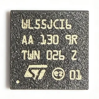
CI522 - 13.56MHz ISO14443A RFID Reader IC QFN-16 | Nanjing Zhongke
Артикул: CI522 ✓ Активен| Кол-во | Цена за ед. | Итого |
|---|---|---|
| 1 | $0.32 | $0,32 |
| 10 | $0.3 | $3,00 |
| 100 | $0.26 | $26,00 |
| 500 | $0.23 | $115,00 |
| 1.000 | $0.21 | $210,00 |
| 3.000 | $0.18 | $540,00 |
CI522 Обзор
What is an RFID reader IC? An RFID reader IC (radio-frequency identification reader IC) is a contactless front-end transceiver that powers a passive transponder (tag or card) over a magnetic field at 13.56 MHz, exchanges modulated data using a defined air protocol such as ISO/IEC 14443 A/B or ISO 15693, and presents a digital interface (SPI, UART, I2C) to a host microcontroller. It belongs to the broader hierarchy: RFID reader IC -> 13.56 MHz NFC front-end -> contactless communication IC -> wireless/RF semiconductor -> semiconductor device. The CI522 implements the type-A sub-protocol of ISO/IEC 14443, which is the most widely deployed air interface for contactless smartcards (MIFARE Classic, MIFARE Ultralight, NTAG) and is the de-facto standard for transit fare cards and access badges.
Key features include an integrated transmit-side antenna driver capable of driving a printed or wound loop directly without an external power amplifier, on-chip CRC and parity verification to offload the host MCU, a configurable low-power wake-up mode that periodically polls the RF field to extend battery life in coin-cell designs, and SPI communication up to 10 Mbit/s. The 3x3 mm QFN-EP package with exposed pad keeps the PCB footprint compact while the thermal pad provides a low-impedance ground reference that is essential for stable RF performance.
Technically, the CI522 combines a 13.56 MHz resonant bridge with modulation/demodulation, anti-collision logic compliant with ISO 14443-3 type A, and a small command engine that handles REQA, SELECT, AUTH, READ, WRITE, and HALT transactions internally. Its low-power wake-up and short command latency enable wake-on-proximity designs where the host sleeps until a card is detected.
Typical applications include access control readers, RFID card writers/programmers for MIFARE Classic 1K/4K and Ultralight tags, smart-locker and shared-mobility kiosks, NFC payment terminals (Type A tags), and battery-powered handheld readers. In each case the CI522 handles the RF and protocol layers so that the host MCU can focus on application logic.
A key design consideration is the antenna matching network - the loop inductance, tuning capacitor, and EMC filter values must be chosen for the specific coil geometry and target card distance; using the recommended reference design from the manufacturer datasheet is the safest path. This page synthesizes distributor pricing, drop-in alternatives, and practical design notes not found in the manufacturer datasheet.
Аналоги без доработки для CI522 — тот же корпус, pin-to-pin совместимость. Компоненты в других корпусах, требующие переработки PCB, исключены.
Варианты в этой серии
Модели той же серии, совместимые без доработки с CI522 (тот же форм-фактор и посадочное место) — отличается по Function, Package, RoHS Status, Supply Voltage, Supported Protocol.
Инструмент быстрого сравнения — выберите альтернативные компоненты для сравнения бок о бок:
CI521
✅ Прямая замена✓ В наличии
Уточнить цену
Открыть даташит →CI523
✅ Прямая замена📋 Справочный аналог (нет в каталоге)
CI520
✅ Прямая замена📋 Справочный аналог (нет в каталоге)
MFRC52201HN1,115
✅ Прямая замена✓ В наличии
$4.1 / шт.
Открыть даташит →FM17550
✅ Прямая замена📋 Справочный аналог (нет в каталоге)
CI522 Характеристики
| Manufacturer | Nanjing Zhongke Microelectronics |
| Функция | 13.56 MHz contactless reader/writer IC |
| Supported Protocol | ISO/IEC 14443 Type A |
| Operating Frequency | 13.56 MHz |
| Maximum Data Rate | 848 Kbit/s |
| Напряжение питания | 2.3 V to 4 V |
| Host Interface | SPI |
| Built-in Antenna Driver | Yes |
| Hardware Data Verification | CRC and parity, on-chip |
| Low-Power Wake-up | Yes (configurable polling) |
| Корпус | QFN-16-EP (3x3 mm) |
| Тип монтажа | Surface Mount |
| Статус RoHS | Compliant (per JLCPCB listing) |
Конфигурация выводов CI522
| Контакт 1 | VCC — Power supply input (2.3 V to 4 V) |
| Контакт 2 | GND — Ground |
| Контакт 3 | RST — Reset input, active low |
| Контакт 4 | IRQ — Interrupt request output to host MCU |
| Контакт 5 | SCLK — SPI serial clock from host |
| Контакт 6 | MOSI — SPI master-out, slave-in (host to CI522) |
| Контакт 7 | MISO — SPI master-in, slave-out (CI522 to host) |
| Контакт 8 | CS — SPI chip-select, active low |
| Контакт 9 | TX1 — Antenna driver output 1 |
| Контакт 10 | TX2 — Antenna driver output 2 |
| Контакт 11 | AUX1 — Auxiliary analog input |
| Контакт 12 | AUX2 — Auxiliary analog input |
| Контакт 13 | WAKE — Low-power wake-up control |
| Контакт 14 | TEST — Test mode pin, leave open in application |
| Контакт 15 | NC — Not connected (per datasheet) |
| Контакт 16 | EP — Exposed pad, thermal/ground return - solder to PCB ground |
Типичное применение
CI522 подходит для 7 применениеs: Access Control Reader, MIFARE Ultralight Card Programmer, Smart Locker / Shared-Mobility Kiosk, NFC Payment Terminal (Type A only), Battery-Operated Handheld RFID Reader, Industrial IoT Reader Module, Vending and Amusement Reader.
Access Control Reader
The CI522's ISO/IEC 14443 Type A engine and 848 Kbit/s air-interface data rate make it well suited for fixed-mount access-control readers mounted on doors, turnstiles, and elevators that read MIFARE Classic or Ultralight credentials. According to the Nanjing Zhongke datasheet, the on-chip antenna driver directly drives the reader loop so the BOM stays small, and on-chip CRC/parity offloads verification from the host MCU, allowing an 8-bit microcontroller to handle credential logic with low firmware burden. Placed at the door-mounted reader PCB with a 50 mm loop antenna and matching network values from the datasheet reference design, CI522 reads cards at the typical 5 to 7 cm range demanded by office access-control products.
Рекомендуется
MIFARE Ultralight Card Programmer
For NFC tag and MIFARE Ultralight card programmers used in production lines or kiosk printers, the CI522's native ISO 14443 Type A support and 848 Kbit/s throughput keep tag-write times short, while the on-chip CRC and parity blocks eliminate extra code paths in firmware. According to the manufacturer reference design, the CI522 sits between the host PC (over USB-UART bridge plus SPI) and the antenna PCB, with a typical full Ultralight page write completed in a few milliseconds. Designers choose CI522 here over older Type A readers because the integrated TX driver shrinks the BOM and the 3x3 mm QFN-EP fits alongside small PCB antennas in handheld printers.
Рекомендуется
Smart Locker / Shared-Mobility Kiosk
The CI522's low-power wake-up mode enables battery-powered smart-locker and shared-mobility kiosks that periodically poll for a card and otherwise sit in standby. According to the Nanjing Zhongke datasheet, low-power wake-up combined with SPI host side gating lets a locker reader draw very little idle current between user taps, extending battery life on the order of a year versus a few months when the host MCU continuously polls. The 3x3 mm QFN-EP footprint also helps fit the reader electronics inside the small kiosk bezel. Placed at the user-facing bezel with a 30 mm loop antenna, CI522 detects the user's MIFARE Classic or Ultralight badge within 4 to 5 cm.
Рекомендуется
NFC Payment Terminal (Type A only)
The CI522 supports closed-loop NFC payment terminals where cards and tokens are MIFARE Ultralight or similar Type A products. According to the Nanjing Zhongke datasheet, the on-chip hardware verification of CRC and parity lets a Cortex-M0 host apply business logic with low firmware footprint, and the integrated antenna driver avoids the cost and PCB area of a discrete PA. Designers choose CI522 here when the terminal scope is single-protocol Type A and BOM cost matters more than the multi-protocol flexibility of an NXP CLRC663. The 16-pin QFN-EP lets the reader PCB sit on the back of a small PIN-pad enclosure.
Рекомендуется
Battery-Operated Handheld RFID Reader
For battery-powered handheld RFID readers used in warehouse inventory and asset tracking, the CI522's low-power wake-up and 13.56 MHz native protocol stack keep idle and active current low enough that two AA cells power a full shift. According to the manufacturer datasheet, the on-chip antenna driver and integrated CRC/parity drop the parts count below a discrete MFRC522 design, lowering both BOM cost and weight. Combined with a Cortex-M0 host, the handheld reader weighs under 200 g, fits in a coat pocket, and reads a stack of tags within 5 cm range in 200 to 500 ms each.
Рекомендуется
Industrial IoT Reader Module
The CI522's small 3x3 mm QFN-EP footprint, integrated antenna driver, and SPI host interface make it a drop-in Type A reader for industrial IoT modules that need to identify tagged workpieces, fixtures, or consumables. According to the Nanjing Zhongke datasheet, the IC operates over the 2.3 V to 4 V supply range compatible with 3.3 V industrial MCUs, and the SPI host can be shared with other peripherals on the same bus via the chip-select pin. In a typical IoT gateway the CI522 reader block lives next to the main MCU and a small PCB antenna, identifying tagged tools or consumables on the production line in real time.
Рекомендуется
Vending and Amusement Reader
Vending machines and amusement devices that accept contactless stored-value cards use the CI522's 848 Kbit/s throughput to keep tap-to-pay times under 200 ms. According to the Nanjing Zhongke datasheet, the integrated antenna driver and on-chip CRC eliminate the need for an external PA and let a low-cost 8-bit MCU drive the reader. A typical vending reader design places the CI522 near the coin slot with a 25 mm loop antenna, accepting MIFARE Classic or Ultralight payment tokens across the 3 to 5 cm tap zone required by self-service kiosks.
Рекомендуется
Сводка рекомендуемых товаров
Справочные инженерные данные для CI522 — сравнение, рекомендации по проектированию и информация о соответствии.
Руководство по выбору
Сравнение с аналогами
| Параметр | Этот товар | CI521 | CI523 | CI520 | FM17550 |
|---|---|---|---|---|---|
| Brand | Nanjing Zhongke Microelectronics | Nanjing Zhongke Microelectronics | Nanjing Zhongke Microelectronics | Nanjing Zhongke Microelectronics | Fudan Microelectronics |
| Package | QFN-16-EP (3x3 mm) | QFN-16-EP (3x3 mm) - same | QFN-16-EP (3x3 mm) - same | QFN-16-EP (3x3 mm) - same | QFN-16-EP (3x3 mm) - same |
| Supported Protocol | ISO/IEC 14443 Type A | ISO/IEC 14443 Type A | ISO/IEC 14443 Type A + B | ISO/IEC 14443 Type A | ISO/IEC 14443 Type A |
| Maximum Air-Interface Data Rate | 848 Kbit/s | 848 Kbit/s | 848 Kbit/s | 424 Kbit/s | 848 Kbit/s |
| Supply Voltage Range | 2.3 V to 4 V | 2.3 V to 4 V | 2.3 V to 4 V | 2.3 V to 4 V | 2.7 V to 3.6 V |
| Host Interface | SPI | SPI | SPI | SPI | SPI |
| Built-in Antenna Driver | Yes | Yes | Yes | Yes | Yes |
| Low-Power Wake-up | Yes | Yes | Yes | Yes | Yes |
Ключевые отличия
- Smallest QFN-16 footprint in its 13.56 MHz Type A reader class (против CI520)
- Single-protocol Type A focus keeps firmware simple (против CI523)
- Chinese-domestic RF reader IC at competitive cost (против FM17550 (Fudan Microelectronics))
Заметки по проектированию
Place the 16-pin QFN-EP CI522 with the exposed pad soldered to a continuous PCB ground pour; the thermal/ground return path is essential to keep the on-chip antenna driver stable under load. According to the Nanjing Zhongke datasheet, all four matching-network components (tuning capacitor, EMC filter inductor and capacitor) must be placed within 5 mm of the TX1/TX2 pins to keep the resonant loop short and Q high. Recommended: keep the antenna loop trace on the top layer directly under the PCB loop antenna with no via stitching, so the magnetic coupling remains uniform across the read zone.
Add a 100 nF X7R ceramic decoupling capacitor within 2 mm of the VCC pin (pin 1) and a 10 uF bulk capacitor near the antenna-driver supply rail. According to the manufacturer reference design, the analog and digital sections of the CI522 are sensitive to VCC ripple during RF bursts, and inadequate decoupling can pull the resonant loop off-tune by 1 to 2 percent, shrinking the read range. Use a low-ESR ceramic; tantalum and aluminum electrolytic do not provide adequate high-frequency bypass for 13.56 MHz operation.
Do not operate CI522 above the 4 V absolute maximum on VCC; the on-chip antenna driver outputs can be permanently damaged. Avoid running long SPI cables between the host MCU and CI522 - keep the SPI bus under 50 mm with a clean ground return, or add a series resistor near the host to dampen ringing. According to the Nanjing Zhongke datasheet, the firmware must wait for the IRQ pin to assert before reading the SPI data register, otherwise polling is required and host latency becomes unpredictable on busy multi-protocol traffic.
Tune the antenna loop to exactly 13.56 MHz with the matching network from the manufacturer reference design; a detuned loop degrades read range and can cause CRC errors. Estimated: a 35 mm x 35 mm square loop made of 1 mm trace over FR4 exhibits roughly 1 uH of inductance and typically pairs with a 100 pF trim capacitor and pi-network of 100 nH/100 pF series/parallel values; verify with a vector network analyzer. Without proper tuning the CI522 will power up correctly but fail to read cards beyond 1 cm.
Информация о соответствии
RoHS compliance confirmed via JLCPCB part page (snippet states ROHS). REACH, AEC-Q100, halogen-free, and conflict-minerals status not stated in the verified web data and left as 'unknown'.