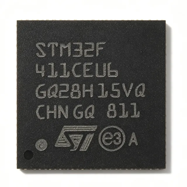
STM32F411CEU6 - 100MHz Cortex-M4F 512KB MCU | STMicroelectronics
Артикул: STM32F411CEU6 ✓ Активен| Кол-во | Цена за ед. | Итого |
|---|---|---|
| 1 | $5.21 | $5,21 |
| 10 | $4.72 | $47,20 |
| 100 | $4.25 | $425,00 |
| 500 | $3.87 | $1.935,00 |
| 1.000 | $3.48 | $3.480,00 |
STM32F411CEU6 Обзор
A microcontroller (MCU) is a compact integrated circuit that combines a processor core, memory, and programmable peripherals to govern a specific operation in an embedded system. MCUs sit within the broader hierarchy of ARM Cortex-M processors, flash microcontrollers, and power management/embedded control semiconductors. The STM32F411 belongs to the STM32F4 'Dynamic Efficiency' series from STMicroelectronics, part of the wider STM32 32-bit MCU family built on the ARM Cortex-M architecture.
Key features include the Cortex-M4F core with single-precision FPU and DSP instructions delivering 125 DMIPS (1.25 DMIPS/MHz), 512 KB flash with 128 KB SRAM, a wide 1.7 V to 3.6 V supply range, and ST's Batch Acquisition Mode (BAM) for reduced power consumption during data conversion. Peripherals include USB OTG FS/HS, SDIO, I2S, multiple SPI/I2C/USART interfaces, 12-bit ADC, general-purpose timers, RTC, and a memory protection unit (MPU).
Technically, the device is fabricated on ST's 90 nm process and features dynamic voltage scaling with multiple low-power modes (Sleep, Stop, Standby), enabling battery-powered designs with excellent performance-per-milliamp. The ART accelerator and 128-bit wide flash interface allow zero-wait-state execution at this clock speed tier.
Typical applications include IoT end nodes, wearable electronics, motor control, audio processing, drones, and industrial automation, where the FPU and DSP instructions accelerate sensor fusion and control algorithms.
Design-wise, decouple each VDD pin with 100 nF capacitors placed close to the pins, keep VDDA on a clean analog supply, and configure BOOT0 correctly for the desired boot source.
This page synthesizes distributor pricing, drop-in alternatives, and practical design notes not found in the STMicroelectronics datasheet.
Аналоги без доработки для STM32F411CEU6 — тот же корпус, pin-to-pin совместимость. Компоненты в других корпусах, требующие переработки PCB, исключены.
Варианты в этой серии
Модели той же серии, совместимые без доработки с STM32F411CEU6 (тот же форм-фактор и посадочное место) — отличается по SRAM, Core, Timers, Package, Flash Memory.
Инструмент быстрого сравнения — выберите альтернативные компоненты для сравнения бок о бок:
STM32F412CEU6
✅ Прямая замена✓ В наличии
$4.16 / шт.
Открыть даташит →STM32F411CCU6
✅ Прямая замена✓ В наличии
$2.96 / шт.
Открыть даташит →STM32F411CEU7
✅ Прямая замена📋 Справочный аналог (нет в каталоге)
STM32F401CEU6
✅ Прямая замена✓ В наличии
$2.88 / шт.
Открыть даташит →STM32F413CGU6
✅ Прямая замена✓ В наличии
$5.44 / шт.
Открыть даташит →STM32F411CEU6 Максимальные параметры и электрические характеристики
| Core | ARM Cortex-M4F 32-bit |
| Максимальная тактовая частота | 100 MHz |
| Flash Memory | 512 KB |
| SRAM | 128 KB |
| Performance | 125 DMIPS / 1.25 DMIPS/MHz |
| Supply Voltage Range | 1.7 V to 3.6 V |
| Рабочая температура | -40 C to +85 C |
| Корпус | 48-UFQFPN (7x7 mm) exposed pad |
| Тип монтажа | Surface Mount |
| ADC | 12-bit, up to 16 channels |
| Communication Interfaces | USART, SPI, I2C, I2S, SDIO, USB OTG FS |
| Timers | General-purpose, advanced, SysTick, RTC |
| DMA | Yes, 16-stream DMA controller |
| FPU | Single-precision floating-point unit |
| MPU | Memory Protection Unit |
| Low Power Modes | Sleep, Stop, Standby, Batch Acquisition Mode (BAM) |
| Статус RoHS | Compliant |
Конфигурация выводов STM32F411CEU6
| Контакт 1 | VBAT — Battery backup supply for RTC |
| Контакт 2 | PC13 — GPIO port C, pin 13 |
| Контакт 3 | PC14 — GPIO port C, pin 14 / OSC32_IN |
| Контакт 4 | PC15 — GPIO port C, pin 15 / OSC32_OUT |
| Контакт 5 | PH0 — GPIO / OSC_IN (HSE) |
| Контакт 6 | PH1 — GPIO / OSC_OUT (HSE) |
| Контакт 7 | NRST — System reset (active low) |
| Контакт 8 | PC0 — GPIO port C, pin 0 / ADC input |
| Контакт 9 | PC1 — GPIO port C, pin 1 / ADC input |
| Контакт 10 | PC2 — GPIO port C, pin 2 / ADC input |
| Контакт 11 | PC3 — GPIO port C, pin 3 / ADC input |
| Контакт 12 | VSSA — Analog ground |
| Контакт 13 | VDDA — Analog power supply |
| Контакт 14 | PA0 — GPIO port A, pin 0 / WKUP / ADC |
| Контакт 15 | PA1 — GPIO port A, pin 1 / ADC |
| Контакт 16 | PA2 — GPIO port A, pin 2 / USART2_TX / ADC |
| Контакт 17 | PA3 — GPIO port A, pin 3 / USART2_RX / ADC |
| Контакт 18 | VDD — Digital power supply |
| Контакт 19 | PA4 — GPIO port A, pin 4 / SPI1_NSS / DAC-related / ADC |
| Контакт 20 | PA5 — GPIO port A, pin 5 / SPI1_SCK / ADC |
| Контакт 21 | PA6 — GPIO port A, pin 6 / SPI1_MISO / ADC |
| Контакт 22 | PA7 — GPIO port A, pin 7 / SPI1_MOSI / ADC |
| Контакт 23 | PC4 — GPIO port C, pin 4 / ADC input |
| Контакт 24 | PC5 — GPIO port C, pin 5 / ADC input |
| Контакт 25 | PB0 — GPIO port B, pin 0 / ADC input |
| Контакт 26 | PB1 — GPIO port B, pin 1 / ADC input |
| Контакт 27 | PB2 — GPIO port B, pin 2 / BOOT1 |
| Контакт 28 | PB10 — GPIO port B, pin 10 / I2C2_SCL / USART3_TX |
| Контакт 29 | PB11 — GPIO port B, pin 11 / I2C2_SDA / USART3_RX |
| Контакт 30 | VCAP_1 — Core regulator capacitor (external capacitor required) |
| Контакт 31 | VDD — Digital power supply |
| Контакт 32 | PB12 — GPIO port B, pin 12 / SPI2_NSS |
| Контакт 33 | PB13 — GPIO port B, pin 13 / SPI2_SCK |
| Контакт 34 | PB14 — GPIO port B, pin 14 / SPI2_MISO |
| Контакт 35 | PB15 — GPIO port B, pin 15 / SPI2_MOSI |
| Контакт 36 | PC6 — GPIO port C, pin 6 / USART6_TX |
| Контакт 37 | PC7 — GPIO port C, pin 7 / USART6_RX |
| Контакт 38 | PC8 — GPIO port C, pin 8 / SDIO related |
| Контакт 39 | PC9 — GPIO port C, pin 9 / SDIO related |
| Контакт 40 | PA8 — GPIO port A, pin 8 / USART1_CK / MCO1 |
| Контакт 41 | PA9 — GPIO port A, pin 9 / USART1_TX / VBUS sense |
| Контакт 42 | PA10 — GPIO port A, pin 10 / USART1_RX |
| Контакт 43 | PA11 — GPIO port A, pin 11 / USB_OTG_FS_DM |
| Контакт 44 | PA12 — GPIO port A, pin 12 / USB_OTG_FS_DP |
| Контакт 45 | PA13 — GPIO port A, pin 13 / SWDIO (debug) |
| Контакт 46 | VSS — Digital ground |
| Контакт 47 | VDD — Digital power supply |
| Контакт 48 | PA14 — GPIO port A, pin 14 / SWCLK (debug) |
Типичное применение
STM32F411CEU6 подходит для 6 применениеs: IoT End Nodes and Smart Sensors, Drone and Flight Controllers, Wearable Electronics, Motor Control, Audio Processing, Industrial Automation and HMI Nodes.
IoT End Nodes and Smart Sensors
The STM32F411CEU6 fits IoT end nodes through its combination of 100 MHz Cortex-M4F processing, 512 KB flash for protocol stacks, and low-power modes. Sleep, Stop, and Standby modes plus Batch Acquisition Mode allow duty-cycled sensor sampling with minimal average current on coin-cell or Li-ion supplies. USB OTG FS and multiple SPI/I2C/USART interfaces connect Wi-Fi, BLE, and LoRa modules directly. With the FPU accelerating sensor fusion and encryption-friendly 128 KB SRAM, a single chip handles connectivity, signal processing, and application logic, reducing BOM count in connected sensor designs.
Рекомендуется
Drone and Flight Controllers
Drone flight controllers benefit directly from the STM32F411CEU6's 125 DMIPS Cortex-M4F with hardware FPU, which executes PID control loops and quaternion attitude estimation at high update rates. The 512 KB flash holds full flight stacks, while the 12-bit ADC with 16 channels reads battery voltage, current sensors, and analog inputs simultaneously via DMA. Multiple hardware timers generate PWM/PPM outputs for ESCs with precise timing. The compact 7x7 mm UFQFPN-48 package suits weight- and space-critical flight boards, and the -40 C to +85 C range handles automotive-bay and outdoor temperature extremes reliably.
Рекомендуется
Wearable Electronics
Wearables demand small size, long battery life, and sufficient compute for sensor fusion - all strengths of the STM32F411CEU6. The 1.7 V minimum supply allows direct operation from a single Li-ion cell via an LDO, and Standby mode holds RTC state at microamp-level current between wake events. The FPU accelerates step counting and gesture algorithms, while 512 KB flash stores BLE stacks and OTA bootloader code. The 7x7 mm 48-pin QFN footprint with exposed pad simplifies compact PCB layouts typical of wristbands, rings, and health patches, and BAM reduces power during periodic ADC health-signal sampling.
Рекомендуется
Motor Control
The STM32F411CEU6 supports motor control through its advanced PWM timers, 12-bit ADC with fast sampling, and DSP instructions for field-oriented control (FOC) transforms. The Cortex-M4F FPU computes Clarke/Park conversions and PI current loops without fixed-point overhead, enabling smooth sinusoidal drive of BLDC and PMSM motors. Hardware timers provide complementary PWM outputs with dead-time insertion, while DMA-offloaded ADC sampling synchronizes current measurements to PWM cycles. The 100 MHz core closes inner current loops well above audible frequencies, and BAM mode lowers power in standby equipment between operating cycles.
Рекомендуется
Audio Processing
Audio applications leverage the STM32F411CEU6's I2S interfaces, FPU-accelerated DSP instructions, and 128 KB SRAM for buffering and real-time effects. The device runs FIR/IIR filters, FFT-based spectrum analysis, and sample-rate conversion comfortably at 100 MHz with single-cycle MAC operations. USB OTG FS enables USB audio class device implementations connecting directly to PCs and phones, while SDIO supports local audio file playback from memory cards. With 512 KB flash, full codec driver stacks, EQ tables, and OTA-updatable firmware coexist on-chip, making it a compact single-chip digital audio processor.
Рекомендуется
Industrial Automation and HMI Nodes
In industrial automation, the STM32F411CEU6 serves as a sensor-conditioning, actuator-control, and communication node. Its wide 1.7 V to 3.6 V supply and -40 C to +85 C temperature rating suit cabinet and field installations, while the MPU adds fault containment for safety-adjacent firmware partitioning. Multiple USARTs handle Modbus RTU links, SPI/I2C connect isolated ADCs and I/O expanders, and timers generate precise control pulses. The 12-bit ADC with DMA enables continuous monitoring of analog process signals, and 512 KB flash retains logging logic plus communication stacks with room for firmware updates in the field.
Рекомендуется
Сводка рекомендуемых товаров
Справочные инженерные данные для STM32F411CEU6 — сравнение, рекомендации по проектированию и информация о соответствии.
Руководство по выбору
Сравнение с аналогами
| Параметр | Этот товар | STM32F412CEU6 | STM32F411CCU6 | STM32F401CEU6 | STM32F413CGU6 |
|---|---|---|---|---|---|
| Package | UFQFPN-48 (7x7 mm) | UFQFPN-48 (7x7 mm) - same | UFQFPN-48 (7x7 mm) - same | UFQFPN-48 (7x7 mm) - same | UFQFPN-48 (7x7 mm) - same |
| Brand | STMicroelectronics | STMicroelectronics | STMicroelectronics | STMicroelectronics | STMicroelectronics |
| Core / Max Clock | Cortex-M4F, 100 MHz | Cortex-M4F, 100 MHz | Cortex-M4F, 100 MHz | Cortex-M4F, 84 MHz | Cortex-M4F, 100 MHz |
| Flash Memory | 512 KB | 512 KB | 256 KB | 512 KB | 1 MB |
| SRAM | 128 KB | 128 KB | 128 KB | 96 KB | 160 KB |
| Batch Acquisition Mode | Yes (BAM) | Yes | Yes | No | Yes |
| Operating Temperature | -40 C to +85 C | -40 C to +85 C | -40 C to +85 C | -40 C to +85 C | -40 C to +85 C |
| Supply Voltage | 1.7 V to 3.6 V | 1.7 V to 3.6 V | 1.7 V to 3.6 V | 1.7 V to 3.6 V | 1.7 V to 3.6 V |
Ключевые отличия
- Highest-performance 100 MHz option in the pin-compatible family with BAM (против STM32F401CEU6)
- Full 512 KB flash at family-best value (против STM32F411CCU6)
- Cost-optimized alternative to feature-extended siblings (против STM32F413CGU6)
Заметки по проектированию
Decouple every VDD pin with a 100 nF ceramic capacitor placed as close to the pin as possible, plus one bulk 4.7 uF to 10 uF capacitor on the board. VDDA requires its own 100 nF capacitor plus a 1 uF capacitor and, in noisy designs, an RC filter (ferrite bead + capacitor) from the main 3.3 V rail to keep ADC noise low. The VCAP_1 pin (pin 30) requires an external 2.2 uF ceramic capacitor to ground for the internal 1.2 V core regulator - never omit it or the core will not stabilize.
BOOT0 must be tied to GND through a 10 k resistor for normal flash boot; leaving it floating can cause sporadic boot from system memory after reset. During SWD programming, PA13/PA14 (SWDIO/SWCLK) are reserved by default - plan board test points accordingly. PC14/PC15 default to 32 kHz crystal functions and have limited output current capability; verify datasheet restrictions before using them as GPIO loads. NRST has an internal pull-up but adding an external 100 nF capacitor improves power-on-reset robustness.
Route USB OTG FS (PA11/PA12) as a 90-ohm differential pair with length-matched traces and keep the pair away from switching regulators and crystal circuitry. The 8 MHz HSE crystal should sit within a few millimeters of PH0/PH1 with short ground-guarded traces and correct load capacitors per crystal specification. The UFQFPN-48 exposed pad should be soldered to a grounded pad array for thermal relief and ground integrity - relying on perimeter pins alone degrades EMC performance.
Estimated: an STM32F411CEU6 at 100 MHz drawing roughly 30-40 mA from 3.3 V dissipates only about 0.10-0.13 W, and with the UFQFPN-48 exposed-pad thermal resistance of tens of C/W the junction temperature rise is a few degrees C above ambient - no heatsinking is needed for typical operation. Thermal concerns only arise in extended-temperature designs near +85 C ambient with all peripherals active; verify with ST's STM32CubeMX power calculator for your exact configuration.
Информация о соответствии
RoHS compliant and lead-free per STMicroelectronics product data. Not an automotive AEC-Q100 part; -40 C to +85 C industrial temperature range.







