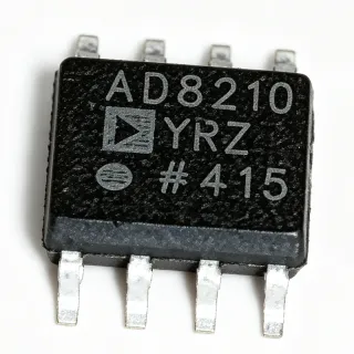
IR2175STRPBF - 600V Linear Current Sense IC, 8-SOIC | Infineon
MPN: IR2175STRPBF ✓ فعالIR2175STRPBF جائزہ
A current sense regulator (also called a linear current sensing IC) is a category of power-management IC that converts a small analog shunt voltage into an isolated, scaled, and noise-immune representation of load current. These ICs sit in the signal chain between a low-side shunt resistor and the controller, providing galvanic isolation between the power stage and logic. The IR2175 family belongs to Infineon's high-voltage gate-driver and sensor portfolio, positioned above simple op-amp current shunts and below isolated delta-sigma modulators.
Key features include 9.5 V to 20 V low-side supply (VCC), 13 V to 20 V high-side floating supply (VB), 2 mA quiescent current on the bootstrap rail (IQBS), 20 mA output current capability, 130 kHz typical PWM output frequency, and ±260 mV input common-mode range with 20 ppm/°C gain temperature drift. An independent fast overcurrent trip signal activates within 2 µs typical delay when the input threshold is exceeded, providing hardware-level short-circuit protection independent of the PWM feedback path.
Architecturally, the IR2175 combines a high-side differential amplifier with an internal level shifter, allowing the low-voltage DSP or MCU to read high-side phase current without external isolation. The monolithic integration of the floating channel eliminates optocoupler drift and propagation delay, supporting high-bandwidth FOC (field-oriented control) loops in variable-frequency drives.
Typical applications include three-phase motor drives, HVAC compressors, industrial servo amplifiers, and EV traction inverters. The wide 600 V floating-channel range covers 230 V and 480 V rectified bus voltages with substantial headroom. Designers select the IR2175 when they need a simple, low-BOM current-feedback path for variable-speed drives.
Designers should size the external shunt to keep peak current below ±260 mV, observe PCB creepage/clearance for the floating pins, and provide adequate bootstrap capacitance to sustain the high-side supply. Compared to discrete op-amp solutions, the IR2175 reduces part count and eliminates calibration of the gain drift.
This page synthesizes distributor pricing, drop-in alternatives, and practical design notes not found in the manufacturer datasheet, helping procurement and firmware teams select, source, and validate a 600 V current-sense IC in a single document.
کے لیے ڈراپ اِن متبادل IR2175STRPBF — یکساں پیکیج، پن سے پن مطابقت پذیر۔ مختلف پیکیج والے پرزے جن کے لیے PCB دوبارہ کام درکار ہو، شامل نہیں ہیں۔
اس سیریز میں مختلف ورژن
اسی سیریز کے ماڈلز جو ڈراپ اِن مطابقت رکھتے ہیں IR2175STRPBF (یکساں فارم فیکٹر اور فٹ پرنٹ) — میں مختلف Package.
IR2175SPBF
✅ ڈراپ-اِن📋 حوالہ جاتی متبادل (کیٹلاگ میں نہیں)
IR2175STRPBF-IR
✅ ڈراپ-اِن📋 حوالہ جاتی متبادل (کیٹلاگ میں نہیں)
IR2277SPBF
✅ ڈراپ-اِن📋 حوالہ جاتی متبادل (کیٹلاگ میں نہیں)
IR21771SPBF
✅ ڈراپ-اِن📋 حوالہ جاتی متبادل (کیٹلاگ میں نہیں)
IR2109SPBF
✅ ڈراپ-اِنقیمت کے لیے رابطہ کریں
ڈیٹا شیٹ دیکھیں →IR2175STRPBF زیادہ سے زیادہ ریٹنگز اور برقی خصوصیات
| Product Type | Linear Current Sensing IC |
| Manufacturer | Infineon (formerly International Rectifier) |
| پیکیج | 8-SOIC (3.90 mm body width) |
| ماؤنٹنگ ٹائپ | Surface Mount |
| Output Current | 20 mA |
| VCC Supply Range | 9.5 V to 20 V |
| VB High-Side Floating Supply | 13 V to 20 V (above VS) |
| VS Floating Supply Offset Voltage | 0.3 V to 600 V |
| Differential Input Voltage (VIN+ to VS) | -260 mV to +260 mV |
| Quiescent Current on VB (IQBS) | 2 mA typical |
| Gain Temperature Drift | 20 ppm/°C typical |
| PWM Output Frequency (fO) | 130 kHz typical |
| Overcurrent Trip Delay | 2 µs typical |
| Overcurrent Trip Level | ±260 mV typical |
| آپریٹنگ درجہ حرارت رینج | -40 °C to +125 °C |
| Channel Type | Floating high-side (monolithic) |
| آؤٹ پٹ کی قسم | Digital PWM (open-drain push-pull) |
| Lead Free / RoHS | Lead Free, RoHS Compliant |
| Packaging | Tape & Reel (Digi-Reel) |
IR2175STRPBF پن کنفیگریشن
| پن 1 | VCC — Low-side and logic fixed supply, 9.5 V to 20 V |
| پن 2 | IN — Differential current-sense input (to external shunt + terminal) |
| پن 3 | VS — High-side floating supply return / shunt low-side reference |
| پن 4 | VB — High-side floating supply (13 V to 20 V above VS) |
| پن 5 | PWM — Digital PWM output (open-drain, duty cycle proportional to current) |
| پن 6 | OC — Overcurrent fault output (active when |VIN+ - VS| > 260 mV) |
| پن 7 | COM — Low-side logic ground reference |
| پن 8 | NC — Not connected (per datasheet) |
عام استعمالات
IR2175STRPBF کے لیے موزوں ہے 6 ایپلیکیشنs: Three-Phase Motor Drive Current Feedback, HVAC Compressor Variable-Frequency Drive, Industrial Servo Amplifier Feedback Path, Solar Inverter Phase Current Monitoring, EV Traction Inverter Current Sense, Uninterruptible Power Supply (UPS) Inverter.
Three-Phase Motor Drive Current Feedback
The IR2175STRPBF sits between the inverter shunt resistor and the microcontroller's timer-capture input in a three-phase motor drive. With a 600 V floating channel and ±260 mV differential input, it tolerates 230 V and 480 V rectified bus voltages while digitizing phase current into a 130 kHz PWM duty cycle. Compared to a discrete op-amp + optocoupler chain, the monolithic integration eliminates calibration of the gain temperature drift (20 ppm/°C typical) and reduces PCB area. The 2 µs overcurrent trip is independent of the feedback PWM and lets a hardware interlock shut down the inverter before the controller reacts, a critical margin in IGBT desaturation events.
تجویز کردہ
HVAC Compressor Variable-Frequency Drive
In a residential or commercial HVAC variable-frequency drive, the IR2175STRPBF provides isolated phase-current feedback for field-oriented control of the compressor motor. The 600 V floating channel handles 230 V AC input rectified to ~325 V DC with margin, while the digital PWM output feeds directly into the DSP's capture pin - no external ADC is needed. Designers size the shunt to keep peak phase current below ±260 mV, then count PWM edges in the controller's timer to recover current magnitude. The 2 µs fault path protects the IGBTs from compressor stall or locked-rotor events without firmware latency.
تجویز کردہ
Industrial Servo Amplifier Feedback Path
Industrial servo amplifiers demand wide-bandwidth current feedback for accurate torque control. The IR2175STRPBF delivers a 130 kHz PWM output, giving the controller 130 000 current samples per second - sufficient bandwidth for high-dynamics servo loops at rotor speeds up to several thousand RPM. The 20 ppm/°C gain drift keeps measurement accuracy stable across the -40 °C to +125 °C industrial temperature range, eliminating per-axis calibration in volume production. The 8-SOIC package drops into compact servo-board layouts alongside gate drivers and isolated power supplies.
تجویز کردہ
Solar Inverter Phase Current Monitoring
In a string inverter or micro-inverter, the IR2175STRPBF monitors the AC-side inductor current for MPPT and grid-synchronization control. The 600 V floating channel covers 480 V AC grid voltages with adequate derating, while the digital PWM output couples to the inverter controller through a single low-cost optocoupler. The 2 mA IQBS quiescent current minimizes losses on the bootstrap supply, important in efficiency-sensitive solar designs. The 2 µs hardware overcurrent trip protects against grid-side short circuits within one line cycle.
تجویز کردہ
EV Traction Inverter Current Sense
In an EV traction inverter the IR2175STRPBF provides per-phase current feedback to the motor controller MCU. The 600 V floating channel tolerates 400 V and 800 V traction battery buses (within derating), while the 2 µs overcurrent trip provides hardware desaturation protection in coordination with the gate driver. The 130 kHz PWM output frequency keeps current-loop bandwidth high enough for smooth torque ripple control at low rotor speeds. Designers must observe PCB creepage between the floating pins and the low-voltage logic side per IEC 60664.
تجویز کردہ
Uninterruptible Power Supply (UPS) Inverter
In a double-conversion UPS, the IR2175STRPBF senses the inverter-leg current to regulate output voltage and current. The wide 9.5 V to 20 V VCC range operates directly from a 15 V auxiliary rail, while the digital PWM output simplifies isolation to the supervisory DSP. The 2 µs hardware fault trip provides a fast inverter shutdown on output overcurrent or short-circuit, complementing the firmware-based protection. The monolithic 600 V floating channel reduces component count compared to discrete Hall-effect current sensors, saving PCB space and BOM cost.
تجویز کردہ
تجویز کردہ پروڈکٹس کا خلاصہ
کے لیے انجینئرنگ ریفرنس ڈیٹا IR2175STRPBF — موازنہ، ڈیزائن رہنمائی، اور تعمیل کی معلومات۔
انتخاب کی گائیڈ
متبادلات کے ساتھ موازنہ
| پیرامیٹر | یہ پروڈکٹ | IR2175SPBF | IR21771SPBF | IR2277SPBF | IR2109SPBF |
|---|---|---|---|---|---|
| Brand | Infineon | Infineon | Infineon | Infineon | Infineon |
| Package | 8-SOIC | 8-SOIC - same | 8-SOIC - same | 8-SOIC - same | 8-SOIC - same |
| Function | Current Sense IC | Current Sense IC | Current Sense IC | Current Sense IC | Half-Bridge Gate Driver |
| Floating Channel Voltage | 600 V | 600 V | 600 V | 600 V | 600 V (boot to VS+) |
| Differential Input Range | ±260 mV | ±260 mV | ±260 mV | ±200 mV | N/A (gate driver) |
| Output Format | Digital PWM, 130 kHz | Digital PWM, 130 kHz | Digital PWM, 130 kHz | Digital PWM | Gate-drive HO/LO outputs |
| VCC Supply Range | 9.5 V to 20 V | 9.5 V to 20 V | 9.5 V to 20 V | 9.5 V to 20 V | 10 V to 20 V |
| Unit Price (1 pc) | $3.62 | ~$3.50 | ~$3.80 | ~$3.20 | ~$1.40 |
اہم امتیازی خصوصیات
- Monolithic 600 V floating channel eliminates optocoupler isolation chain (بمقابلہDiscrete op-amp + optocoupler current-sense chain)
- Direct digital PWM output simplifies microcontroller interface (بمقابلہAnalog-output current sense ICs requiring external ADC)
- Independent 2 µs hardware overcurrent trip runs in parallel to PWM feedback (بمقابلہFirmware-only overcurrent detection)
ڈیزائن نوٹس
Place the IR2175STRPBF as close as possible to the current-shunt resistor to minimize ground-bounce pickup on the differential IN/VIN pins. Use a Kelvin connection (4-wire) from the shunt to the IC inputs, with traces routed as a tightly-coupled differential pair. Maintain at least 6 mm creepage between the high-side floating pins (VB, VS) and the low-side logic pins (VCC, COM, PWM, OC) per IEC 60664 for 230 V AC and 480 V AC systems.
The IR2175STRPBF draws 2 mA quiescent current from the VB bootstrap rail. Size the bootstrap capacitor Cboot for Cboot >= (IQBS + IIN_bias) × t_on / ΔV, where t_on is the maximum high-side on-time per PWM cycle and ΔV is the allowed droop (typically 0.5 V). For a 10 kHz switching frequency and 50% duty cycle, a 100 nF X7R ceramic in parallel with a 1 µF electrolytic is a robust starting point.
Do not exceed the ±260 mV differential input range - input voltages above this will trigger the overcurrent trip and may saturate the input differential amplifier. For peak phase currents above the maximum shunt-rated value, increase the shunt resistance rather than risk saturating the IR2175. Also ensure the bootstrap diode is a fast-recovery type (tRR < 100 ns); standard rectifiers will overheat at high switching frequency.
تعمیل کی معلومات
PbF suffix confirms lead-free and RoHS compliance per Infineon product page. Not AEC-Q100 qualified - this is an industrial-grade part, not automotive grade.