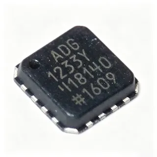
ADF5610BCCZ-RL7 - 14.6 GHz Integrated VCO PLL | Analog Devices
MPN: ADF5610BCCZ-RL7 ✗ Cuối đờiADF5610BCCZ-RL7 Tóm tắt
An integrated VCO is a frequency-control component that combines a voltage-controlled oscillator with active frequency-generation circuitry. In the ADF5610, the VCO has a fundamental frequency range of 3650 MHz to 7300 MHz. The fundamental signal is internally doubled and routed to the RFOUT pin, while a differential output provides additional divided frequencies. This architecture places the synthesizer between RF signal-generation functions and wider communications, test, and instrumentation systems.
The ADF5610 supports a broad tuning range from approximately 57 MHz at the lowest divided output to 14.6 GHz at the highest output. Its 3-wire serial interface provides programming access for configuration and control. The device is suitable for wideband microwave synthesizer implementations where integrating the VCO into the synthesizer simplifies the RF signal chain and reduces the number of separate frequency-generation components.
The core operating principle is fractional-N or integer-N PLL synthesis using an external loop filter and external reference source. The differential divided output can provide divided VCO frequencies, enabling flexible output planning across wideband systems. The integrated VCO also supports a calibration sequence, with a temperature-related calibration voltage available at VPRST for die-temperature estimation during operation.
Typical uses include microwave communications modules, radar and test equipment, frequency-conversion subsystems, and wideband RF signal generators. The 48-VFLGA exposed-pad package is intended for surface-mount assembly and requires careful PCB thermal management and short RF connections. The ADF5610BCCZ-RL7 is marked obsolete by the manufacturer’s distributor listing, so new designs should confirm lifecycle status and consider the current ADF5610 product family options before releasing production quantities.
Bộ thay thế dễ dàng lắp đặt cho ADF5610BCCZ-RL7 — cùng gói, chân-to-chân tương thích. Các bộ phận yêu cầu hàn PCB bị loại trừ.
Các biến thể trong loạt này
Các mẫu cùng loạt có thể lắp đặt dễ dàng tương thích với ADF5610BCCZ-RL7 (cùng hình factor và footprint) — khác nhau ở Device Type, Package.
ADF5610BCCZ
✅ Drop-InLiên hệ để biết giá
Xem tài liệu →ADF5611
✅ Drop-In📋 Tham chiếu thay thế (không có trong danh mục)
ADF5612
✅ Drop-In📋 Tham chiếu thay thế (không có trong danh mục)
ADF5613
✅ Drop-In📋 Tham chiếu thay thế (không có trong danh mục)
LTC6957
✅ Drop-In📋 Tham chiếu thay thế (không có trong danh mục)
ADF5610BCCZ-RL7 Thông số kỹ thuật
| Device Type | Microwave wideband synthesizer with integrated VCO |
| PLL Architecture | Integer-N or fractional-N phase-locked loop |
| Maximum RF Output Frequency | 14.6 GHz |
| Fundamental VCO Frequency Range | 3650 MHz to 7300 MHz |
| Minimum Divided RF Output Frequency | 57 MHz |
| Divided Output Ratios | 1, 2, 4, 8, 16, 32, 64, or 128 |
| Serial Interface | 3-wire SPI |
| Reference Requirement | External reference source |
| Loop Filter | External |
| Hộp | 48-VFLGA exposed-pad package |
| Package Pin Count | 48 pins |
| Kiểu lắp đặt | Surface mount |
| Kiểu đầu ra | Differential divided RF output and doubled VCO output |
| Calibration Voltage Pin | VPRST, Pin 35 |
| Temperature Grade | Industrial |
Hướng dẫn cấu hình chân ADF5610BCCZ-RL7 48 pins
Cấu hình chân cho ADF5610BCCZ-RL7 (48 pins gói). Số thứ tự chân, chức năng và sơ đồ kết nối được xác định trong tài liệu thông số kỹ thuật của nhà sản xuất. Tham khảo nó để biết footprint và hướng dẫn hàn chính xác.

Không có dữ liệu chân cụ thể sẵn có cho ADF5610BCCZ-RL7.
Tham khảo: tài liệu kỹ thuật cho cấu hình chân đầy đủ.
Ứng dụng tiêu biểu
ADF5610BCCZ-RL7 phù hợp cho 6 Áp dụngs: Microwave Communications Modules, Radar and Test Equipment, Frequency Conversion Subsystems, Wideband RF Signal Generators, Microwave Up-Converter Front Ends, RF Calibration and Production Test.
Microwave Communications Modules
The ADF5610BCCZ-RL7 is suitable for wideband microwave communication modules that need an integrated VCO and programmable frequency synthesis in one package. Its fundamental VCO range of 3650 MHz to 7300 MHz and internally doubled output path support RF generation up to 14.6 GHz, reducing the number of separate oscillator and multiplier blocks. The 3-wire SPI interface allows a host controller to configure the synthesizer during system startup or tune the operating channel. In a communication front end, the device can sit behind the reference and loop-filter network and feed a controlled RF signal path. Engineers should preserve short RF traces, provide the manufacturer-recommended decoupling, and validate the loop filter against the required phase noise and lock-time targets.
Được đề xuất
Radar and Test Equipment
The ADF5610BCCZ-RL7 can support radar, instrumentation, and RF test systems requiring programmable wideband RF output. The integrated VCO covers 3650 MHz to 7300 MHz at its fundamental frequency, and the divided output supports ratios of 1, 2, 4, 8, 16, 32, 64, and 128. This division range allows a single synthesizer architecture to serve multiple test frequencies when the system can accept the corresponding output level and spur performance. The external loop filter and reference source are critical to achieving repeatable lock behavior and phase-noise performance. Use controlled impedance routing for RF connections and verify the calibration sequence during power-up before relying on the output for measurement accuracy.
Được đề xuất
Frequency Conversion Subsystems
The ADF5610BCCZ-RL7 is useful in frequency-conversion subsystems where a local oscillator must cover microwave bands while supporting programmable output selection. Its doubled VCO path reaches 14.6 GHz, and the divided differential output provides lower-frequency options down to approximately 57 MHz. This flexibility can simplify the architecture of wideband up-converters, down-converters, and multi-band signal chains. The synthesizer should be referenced to a clean external source and its loop bandwidth should be selected according to the required lock time and phase-noise profile. RF output matching, isolation from noisy digital and switching circuitry, and solid exposed-pad thermal design are essential for maintaining predictable performance in a compact microwave assembly.
Được đề xuất
Wideband RF Signal Generators
The ADF5610BCCZ-RL7 can serve as the core wideband synthesizer in an RF signal generator or laboratory source. The 57 MHz to 14.6 GHz output span, combined with selectable divider ratios, provides flexibility for generating multiple test tones from one integrated frequency-generation block. Its SPI programming interface makes it suitable for automated lab equipment controlled by a microcontroller or embedded processor. Signal-level accuracy still depends on the external reference, loop filter, output matching network, and calibration procedure. Layout should separate sensitive reference and control traces from RF output routing, while the exposed pad requires uninterrupted ground-plane connection for heat transfer. Validate phase noise, spurious content, and lock behavior across the intended operating band.
Được đề xuất
Microwave Up-Converter Front Ends
The ADF5610BCCZ-RL7 is appropriate for microwave up-converter front ends requiring a programmable local oscillator. The high-frequency output capability of 14.6 GHz supports RF synthesis around microwave carrier bands, while the divided outputs can provide local-oscillator signals for lower-frequency conversion stages. The integrated VCO simplifies the synthesizer section compared with a discrete VCO plus multiplier arrangement, although the external reference and loop filter remain necessary. In a compact RF module, control traces and supply routing must be isolated from the local-oscillator path to reduce pulling and unwanted modulation. Use short, impedance-controlled RF connections and validate the synthesizer against the converter’s phase-noise and isolation requirements.
Được đề xuất
RF Calibration and Production Test
The ADF5610BCCZ-RL7 can support automated RF calibration and production-test fixtures that require repeatable wideband frequency generation. Programmable divider ratios and a 3-wire SPI control path allow the test controller to select operating points and capture calibration results efficiently. The external reference quality directly influences frequency repeatability, while the loop-filter design determines lock time and phase noise around each commanded frequency. For production fixtures, isolate the synthesizer from tester switching networks and use stable reference and supply arrangements to reduce measurement variation. The 48-VFLGA package is compact, but its exposed pad and RF pins require careful thermal and assembly design for repeatable performance over temperature and repeated test cycles.
Được đề xuất
Tóm tắt các sản phẩm được đề xuất
Dữ liệu tham khảo kỹ thuật cho ADF5610BCCZ-RL7 — so sánh, hướng dẫn thiết kế và thông tin tuân thủ.
Hướng dẫn chọn lựa
So sánh với các sản phẩm thay thế
| Tham số | Sản phẩm này | ADF5610BCCZ | ADF5611 | ADF5612 | ADF5613 | LTC6957 |
|---|---|---|---|---|---|---|
| Package | 48-VFLGA exposed-pad package | 48-VFLGA exposed-pad package | 48-VFLGA exposed-pad package | 48-VFLGA exposed-pad package | 48-VFLGA exposed-pad package | 48-VFLGA exposed-pad package |
| Brand | Analog Devices | Analog Devices | Analog Devices | Analog Devices | Analog Devices | Analog Devices |
Bảo phân biệt quan trọng
- Integrated VCO reaches a 14.6 GHz maximum RF output (vsADF5611)
- Eight divider choices extend low-frequency flexibility (vsADF5612)
- Integrated microwave synthesizer simplifies frequency generation (vsLTC6957)
Ghi chú thiết kế
Place the external reference, loop-filter, and decoupling networks close to their associated pins. Keep the RF output path short and use a continuous reference plane beneath the RF routing where the board stackup permits. The 48-VFLGA exposed pad should connect to the ground plane through a dense via field, while thermal and RF return-current paths should be reviewed together rather than optimized independently.
Treat the exposed pad as a primary thermal path. Provide uninterrupted copper beneath the device and use multiple thermal vias to distribute heat into the board structure. Validate junction-temperature margin at the highest operating frequency, output level, and ambient temperature. Because the synthesizer integrates an active VCO and PLL, RF-output power, supply dissipation, and ambient conditions should all be included in the thermal verification.
Design the loop filter for the required lock time, phase noise, and reference-spur performance. Keep the SPI control routing away from the sensitive reference and RF nodes, and terminate the interface according to the manufacturer’s recommended configuration. After layout fabrication, verify lock behavior, spur content, and output stability across the full 3650 MHz to 7300 MHz fundamental VCO range and across the commanded divided-output settings.
Do not treat the divided-output frequency as an independent guarantee of output power. Signal amplitude, return loss, and usable frequency can depend on the selected divider and the external output network. Check the datasheet limits for each divider ratio, use the specified reference and filter configurations, and avoid assuming that ADF5611, ADF5612, ADF5613, or LTC6957 can replace the target without a complete pin and specification review.
Thông tin tuân thủ
The target is a commercial microwave synthesizer rather than an automotive-qualified device. Compliance declarations should be confirmed for any remaining legacy inventory before production use.