ESDS312DBVR - ±30kV 2-Channel TVS ESD | Texas Instruments
MPN: ESDS312DBVR ✓ Hoạt độngESDS312DBVR Tóm tắt
A TVS diode array is a circuit-protection semiconductor that diverts transient current away from sensitive circuitry. The ESDS312 belongs to the TVS diode, ESD protection diode, transient suppressor, and discrete semiconductor hierarchy. Its unidirectional structure clamps positive ESD or surge excursions while providing a low-capacitance path for low-voltage data lines.
Verified protection features include ±30 kV contact and air-gap ESD protection, 25 A 8/20 µs surge capability, and a typical 6.5 V clamp voltage listed by DigiKey. The device uses 4.5 pF I/O capacitance per channel, making it suitable for interfaces where added loading and signal degradation must be controlled. TI describes the ESDS312 family as intended for Ethernet, USB, and general-purpose data-line surge protection.
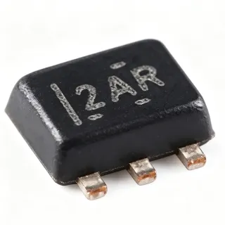
The ESDS312DBVR is supplied in SOT-23-5, a compact surface-mount package in the SOT family. The verified distributor listing identifies the package as SOT-23-5 and describes it as a surface-mount TVS diode. The protection device is intended to be placed close to the connector or board entry point so transient current is intercepted before it reaches sensitive logic.
Typical applications include USB data ports, Ethernet interfaces, communication connectors, and other low-voltage digital data lines. Its 4.5 pF capacitance per channel is the principal signal-integrity consideration: engineers should compare total line capacitance, edge rate, channel count, and connector geometry when assigning protection to high-speed links. The 25 A surge rating also provides a useful distinction from ordinary low-capacacitance ESD-only protection.
The principal design trade-off is that protection capacitance is not zero. Place the device where short transient-current paths and direct ground connections are available, keep the protected trace away from unprotected logic, and verify the PCB return path. This page combines verified manufacturer information, distributor specifications, sourcing data, and practical placement guidance; unavailable electrical details are marked explicitly rather than inferred.
For a drop-in replacement, require the same SOT-23-5 footprint, compatible pin arrangement, comparable channel count, and protection characteristics. The verified alternatives search did not identify a manufacturer-confirmed pin-compatible replacement, so alternatives should not be treated as guaranteed substitutes without checking the original datasheet and PCB layout.
Bộ thay thế dễ dàng lắp đặt cho ESDS312DBVR — cùng gói, chân-to-chân tương thích. Các bộ phận yêu cầu hàn PCB bị loại trừ.
Không có bộ thay thế dễ dàng lắp đặt sẵn có cho sản phẩm này.
Yêu cầu các bộ thay thếESDS312DBVR Thông số kỹ thuật
| Device Type | Dual unidirectional TVS ESD protection diode array |
| Number of Protected Channels | 2 channels |
| Nominal Signal Protection Voltage | 3.6 V |
| Typical Clamp Voltage | 6.5 V |
| Contact ESD Rating | ±30 kV |
| Air-Gap ESD Rating | ±30 kV |
| 8/20 µs Peak Pulse Current | 25 A |
| 8/20 µs Peak Pulse Power | 170 W |
| I/O Capacitance | 4.5 pF per channel |
| Protection Standard | IEC 61000-4-2 ESD; IEC 61000-4-5 8/20 µs surge |
| Application | USB, Ethernet, and general-purpose data-line protection |
| Hộp | SOT-23-5 surface mount |
| Kiểu lắp đặt | Surface mount |
| Polarity | Unidirectional |
| Operating Voltage Context | 3.6 V nominal signal protection |
| Supplier Price | $0.1522 at LCSC as of 2026-10-21 |
| Verified Availability | LCSC listing marked in stock as of 2026-10-21 |
Hướng dẫn cấu hình chân ESDS312DBVR sot-23-5 surface mount
Cấu hình chân cho ESDS312DBVR (sot-23-5 surface mount gói). Số thứ tự chân, chức năng và sơ đồ kết nối được xác định trong tài liệu thông số kỹ thuật của nhà sản xuất. Tham khảo nó để biết footprint và hướng dẫn hàn chính xác.
Không có dữ liệu chân cụ thể sẵn có cho ESDS312DBVR.
Tham khảo: tài liệu kỹ thuật cho cấu hình chân đầy đủ.
Ứng dụng tiêu biểu
ESDS312DBVR phù hợp cho 6 Áp dụngs: USB Data-Port Protection, Ethernet Interface Protection, General Low-Voltage Data-Line Surge Protection, Communication Connector Protection, Low-Voltage Control-Line Protection, Protected External Module Interconnect.
USB Data-Port Protection
ESDS312DBVR fits connector-exposed USB data lines because TI identifies USB as a target application and specifies 4.5 pF of input capacitance per channel. The device provides two protected channels with ±30 kV contact and air-gap ESD ratings, plus a 25 A 8/20 µs surge capability. Place it near the USB connector so transient current is diverted before it reaches the transceiver or controller. The 4.5 pF capacitance is the principal trade-off: it adds loading to the data path, so validate edge rate and signal integrity for the selected USB rate and trace impedance.
Được đề xuất
Ethernet Interface Protection
ESDS312DBVR is suitable for Ethernet data-line protection when the design requires two low-voltage protected channels and limited added capacitance. TI specifically lists Ethernet as an application for the ESDS312 family, while the verified ratings include ±30 kV ESD and 25 A 8/20 µs surge handling. Position the protector at the connector entry point and keep the surge path close to chassis or board ground as appropriate for the product. Validate return loss, insertion loss, common-mode behavior, and the Ethernet standard's isolation requirements in the final board.
Được đề xuất
General Low-Voltage Data-Line Surge Protection
For general-purpose digital data lines, ESDS312DBVR combines two channels, 3.6 V nominal signal protection, and 4.5 pF capacitance per channel in a compact SOT-23-5 package. Its unidirectional TVS structure is appropriate when the protected signal polarity and transient waveform are known. Use the device close to the connector or cable entry point, maintain a short ground return, and verify that the protected logic voltage remains below the device's clamp and absolute-maximum limits. The 25 A 8/20 µs rating adds surge margin beyond ordinary ESD-only protection.
Được đề xuất
Communication Connector Protection
ESDS312DBVR can protect exposed communication-connector contacts when the design operates on low-voltage digital lines. The two-channel arrangement allows one part to protect two conductors, while 4.5 pF capacitance per channel helps limit signal loading. The device should be mounted immediately behind the connector, with protection routing separated from sensitive analog or high-speed circuitry. Confirm the exact SOT-23-5 pin mapping and whether the required interface is unidirectional before layout release. Its verified ±30 kV ESD and 25 A surge ratings are strong component-level indicators, but they do not replace enclosure and system-level ESD design.
Được đề xuất
Low-Voltage Control-Line Protection
ESDS312DBVR may be used on suitable low-voltage control or status lines where transient events can reach a connector or external harness. Its dual-channel format is useful when two related conductors require coordinated protection, while the 4.5 pF capacitance per channel is generally easier to accommodate than a larger protection device on moderate-speed logic. Check the signal's normal voltage, polarity, rise time, and whether a unidirectional clamp is acceptable. Route the device close to the entry point and provide a low-impedance protection return to avoid transferring the surge into the protected system.
Được đề xuất
Protected External Module Interconnect
ESDS312DBVR is useful for external module interconnects where cable transients or ESD events can enter an exposed board connector. The compact SOT-23-5 package helps preserve board area while providing two protected channels and verified ±30 kV ESD capability. Confirm that the module signal voltage is compatible with the 3.6 V nominal protection context and that the data rate tolerates 4.5 pF per channel. Keep the device-side ground return short, inspect the completed assembly for unintended antenna effects, and validate the protection with the actual cable, connector, and enclosure configuration.
Được đề xuất
Tóm tắt các sản phẩm được đề xuất
Dữ liệu tham khảo kỹ thuật cho ESDS312DBVR — so sánh, hướng dẫn thiết kế và thông tin tuân thủ.
Hướng dẫn chọn lựa
So sánh với các sản phẩm thay thế
| Tham số | Sản phẩm này |
|---|---|
| Package | SOT-23-5 surface mount |
| Brand | Texas Instruments |
| Protected Channels | 2 channels |
| Nominal Signal Protection Voltage | 3.6 V |
| Typical Clamp Voltage | 6.5 V |
| I/O Capacitance | 4.5 pF per channel |
| Contact ESD Rating | ±30 kV |
| Air-Gap ESD Rating | ±30 kV |
| 8/20 µs Peak Pulse Current | 25 A |
| 8/20 µs Peak Pulse Power | 170 W |
Bảo phân biệt quan trọng
- Verified 25 A 8/20 µs surge capability (vsGeneric ESD-only protection devices)
- Two protected channels in SOT-23-5 (vsSingle-line discrete TVS solutions)
- Low stated I/O capacitance (vsHigher-capacitance general-purpose TVS arrays)
Ghi chú thiết kế
Place ESDS312DBVR directly behind the connector or cable entry point, with the protected traces short and the transient-current path as low-inductance as practical. Keep the protection device ahead of the first sensitive logic node. The exact SOT-23-5 land pattern and pin mapping must be taken from the official TI datasheet because the supplied search data does not provide that mapping.
Account for the verified 4.5 pF I/O capacitance per channel when assigning the protector to USB, Ethernet, or another high-speed line. Added capacitance can slow edges, alter impedance, and reduce insertion-loss margin. Check the final trace length, connector capacitance, transceiver loading, and target data rate rather than relying only on the ESD rating.
Do not assume that a 6.5 V typical clamp rating is the maximum system voltage or that every transient is safely clamped without considering the protected IC's absolute maximum. Verify normal signal polarity, supply levels, dynamic resistance, pulse waveform, and the protection-device return connection. Use the manufacturer datasheet for the final SOT-23-5 pinout and absolute-maximum limits.
Route the surge or ESD current into the appropriate board ground or protection network using a short, wide path. Avoid routing the transient current through sensitive signal traces or sharing a long return path with analog circuitry. Keep the connector-side protection loop compact and inspect the assembly for unintended coupling between the protected and unprotected sides.
Thông tin tuân thủ
The supplied verified data does not explicitly provide regulatory or material-compliance declarations for ESDS312DBVR. IEC 61000-4-2 and IEC 61000-4-5 are test standards identified in the product information, not compliance certifications.