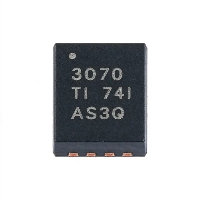
TPS63070RNMT - 2V-16V, 2A Buck-Boost Converter | TI
MPN: TPS63070RNMT ✓ Hoạt độngTPS63070RNMT Tóm tắt
A buck-boost converter is a type of DC-DC switching regulator within the broader power management IC category that combines buck (step-down) and boost (step-up) topologies. This lets a single inductor-based stage produce a stable rail from sources such as 4-cell alkaline, 12V lead-acid, or solar inputs whose voltage swings across the output level. The TPS63070 belongs to the switching voltage regulator family used in portable, industrial, and IoT power systems.
Key features include a 3.6A switch current limit, 2.4MHz switching frequency, and low quiescent current of approximately 50uA typical. Synchronous rectification with integrated MOSFETs improves efficiency and reduces external component count, while the 2.4MHz clock permits small inductors and capacitors for a compact footprint. PWM mode maximizes heavy-load efficiency and PFM mode preserves light-load efficiency; the device also supports negative output current sinking in PWM mode per TI datasheet SLVSDD7B.
Architecture-wise, the four-switch synchronous buck-boost topology seamlessly transitions between buck, buck-boost, and boost operating regions with a single inductor, avoiding output discontinuity when the battery voltage crosses the setpoint. The adjustable feedback (FB) pin sets the output with a resistor divider, and programmable soft-start limits inrush current.
Typical applications include battery-powered portable instruments, industrial sensors, IoT wireless nodes, and 12V rail conditioning for microcontrollers, RF modules, and displays. Wide input tolerance makes it ideal for solar or vehicle-supplied systems.
For best results, keep the inductor and input/output capacitor loops short, place the input capacitor at VIN and PGND, and provide adequate copper on the thermal pad. Pricing references are as of 2026-08-28.
Bộ thay thế dễ dàng lắp đặt cho TPS63070RNMT — cùng gói, chân-to-chân tương thích. Các bộ phận yêu cầu hàn PCB bị loại trừ.
Các biến thể trong loạt này
Các mẫu cùng loạt có thể lắp đặt dễ dàng tương thích với TPS63070RNMT (cùng hình factor và footprint) — khác nhau ở Input Voltage Range, Operating Temperature, Output Type, Output Voltage Range, Package.
TPS63070QRNMTQ1
Liên hệ để biết giá
Xem tài liệu →TPS63070RNMR
📋 Tham chiếu thay thế (không có trong danh mục)
TPS630701RNMR
📋 Tham chiếu thay thế (không có trong danh mục)
TPS630702RNMR
📋 Tham chiếu thay thế (không có trong danh mục)
TPS63070QNMRQ1
📋 Tham chiếu thay thế (không có trong danh mục)
TPS63070RNMT Tỷ lệ tối đa & tính chất điện
| Cấu trúc | Buck-Boost (synchronous) |
| Phạm vi điện áp đầu vào | 2 V to 16 V |
| Khoảng điện áp đầu ra | 2.5 V to 9 V (adjustable) |
| Output Current | 2 A |
| Switch Current Limit | 3.6 A |
| Tần số chuyển đổi | 2.4 MHz |
| Số lượng đầu ra | 1 |
| Kiểu đầu ra | Adjustable (FB pin) |
| Nhiệt độ hoạt động | -40C to +125C (TJ) |
| Hộp | VQFN-HR (RNM), 15 pins |
| Kiểu lắp đặt | Surface Mount |
| Cân bằng đồng bộ | Yes (integrated MOSFETs) |
| Control Modes | PWM / PFM |
| Bắt đầu mềm | Programmable |
| Tắt nhiệt | Yes |
| Negative Current Sinking | Supported in PWM mode |
Cấu hình chân TPS63070RNMT
| Chân 1 | PGND — Power ground |
| Chân 2 | VIN — Power input, 2V-16V |
| Chân 3 | VINA — Analog supply for control circuit |
| Chân 4 | EN — Enable input |
| Chân 5 | SS/TR — Soft-start / tracking pin |
| Chân 6 | FB — Feedback, sets output with resistor divider |
| Chân 7 | PGND — Power ground |
| Chân 8 | SW1 — Switch node 1, connect inductor |
| Chân 9 | SW1 — Switch node 1 |
| Chân 10 | SW2 — Switch node 2, connect inductor |
| Chân 11 | SW2 — Switch node 2 |
| Chân 12 | VOUT — Regulated output, 2.5V-9V |
| Chân 13 | VOUT — Regulated output |
| Chân 14 | GND — Ground |
| Chân 15 | PGND — Power ground / thermal pad |
Ứng dụng tiêu biểu
TPS63070RNMT phù hợp cho 6 Áp dụngs: 12V Rail Conditioning for MCUs and RF Modules, Battery-Powered Portable Instruments, IoT Wireless Sensor Nodes, Solar-Powered Systems, Automotive 12V Subsystems, Display and LED Bias Supplies.
12V Rail Conditioning for MCUs and RF Modules
Industrial control boards often run from 12V or 24V rails that sag or spike across the 5V logic level. The TPS63070RNMT accepts 2V-16V input and regulates a stable 5V at up to 2A, passing seamlessly through buck, buck-boost, and boost regions without output dropout. Its 2.4MHz switching keeps inductors small, and synchronous rectification sustains high efficiency for always-on microcontroller and radio loads.
Được đề xuất
Battery-Powered Portable Instruments
Multi-cell alkaline or lithium battery packs swing from above to below the regulated rail as they discharge. The TPS63070RNMT's 2V-16V input and 2.5V-9V adjustable output maintain regulation across the entire discharge curve, while roughly 50uA quiescent current and PFM light-load mode extend battery life between charges or replacements in handheld test and measurement devices.
Được đề xuất
IoT Wireless Sensor Nodes
Wireless sensor nodes need burst-current capability for radio transmit while idling at microamp levels. The TPS63070RNMT supplies 2A peaks for PA bursts from a 2V-16V solar or battery source, and its PFM mode preserves efficiency at sleep-state loads. The 2.4MHz operation permits a compact inductor, fitting constrained node PCBs. Output set by a single FB resistor divider simplifies rail provisioning.
Được đề xuất
Solar-Powered Systems
Solar panel output voltage varies widely with irradiance and temperature, frequently crossing the battery or load voltage. The TPS63070RNMT's 2V-16V input range and automatic buck-boost transition deliver a constant output from dawn-to-dusk conditions without mode discontinuity, making it a simple single-inductor power stage for solar garden devices, remote telemetry, and energy-harvesting front ends.
Được đề xuất
Automotive 12V Subsystems
With the AEC-Q100 qualified TPS63070QRNMTQ1 sibling, this family serves automotive modules supplied from 12V battery rails that droop during cranking below 6V and surge during load dump. The wide 2V-16V input holds infotainment or sensor-module outputs steady through both conditions, and the 2.4MHz switching keeps switching noise out of the AM radio band, easing EMC compliance.
Được đề xuất
Display and LED Bias Supplies
Small TFT and OLED displays need stable 3.3V-9V rails from battery or USB inputs of varying voltage. The TPS63070RNMT regulates any setpoint in its 2.5V-9V range with 2A capability for display backlight drivers and panel logic. Integrated synchronous FETs and a 2.4MHz clock shrink the solution to a single small inductor, fitting slim display modules with tight height limits.
Được đề xuất
Tóm tắt các sản phẩm được đề xuất
Dữ liệu tham khảo kỹ thuật cho TPS63070RNMT — so sánh, hướng dẫn thiết kế và thông tin tuân thủ.
Hướng dẫn chọn lựa
So sánh với các sản phẩm thay thế
| Tham số | Sản phẩm này | TPS63070QRNMTQ1 | TPS63070RNMR | TPS630701RNMR | TPS630702RNMR |
|---|---|---|---|---|---|
| Package | VQFN-HR (RNM) 15-pin | VQFN-HR (RNM) 15-pin - same | VQFN-HR (RNM) 15-pin - same | VQFN-HR (RNM) 15-pin - same | VQFN-HR (RNM) 15-pin - same |
| Brand | Texas Instruments | Texas Instruments | Texas Instruments | Texas Instruments | Texas Instruments |
| Input Voltage Range | 2V to 16V | 2V to 16V | 2V to 16V | 2V to 16V | 2V to 16V |
| Output Voltage | 2.5V-9V adjustable | 2.5V-9V adjustable | 2.5V-9V adjustable | 3.3V fixed | 5V fixed |
| Output Current | 2 A | 2 A | 2 A | 2 A | 2 A |
| Switch Current Limit | 3.6 A | 3.6 A | 3.6 A | 3.6 A | 3.6 A |
| Switching Frequency | 2.4 MHz | 2.4 MHz | 2.4 MHz | 2.4 MHz | 2.4 MHz |
| AEC-Q100 Qualification | No (standard grade) | Yes | No | No | No |
| Packing | Cut tape / small reel (T) | Cut tape (T) | Tape & reel 3000 (R) | Tape & reel 3000 (R) | Tape & reel 3000 (R) |
Bảo phân biệt quan trọng
- Widest input range in TI buck-boost family (vsTPS63021)
- Automotive-qualified drop-in sibling (vsTPS63070QRNMTQ1)
- Higher output current than small buck-boosts (vsTPS62740DSSR)
Ghi chú thiết kế
Place the input capacitor as close as possible to the VIN and PGND pins, and keep the SW1/SW2-to-inductor loop short and wide. The four-switch buck-boost topology circulates current through both switch nodes, so minimize the copper loop area of SW1-inductor-SW2 to limit radiated EMI at the 2.4MHz switching frequency. Follow TI datasheet SLVSDD7B Section 9 PCB layout guidelines.
The exposed thermal pad must be soldered to a solid ground plane with an array of thermal vias. At VIN=12V, VOUT=5V, 2A load, dissipation is roughly 1-2W depending on efficiency; inadequate copper can push the junction beyond the 125C rating. Use at least 1 square inch of 2oz copper or a buried ground plane under the pad for high-power continuous loads.
Do not omit the SS/TR soft-start capacitor; omitting it causes hard inrush at startup. Ensure the FB divider uses 1% resistors and the FB node is kept short to avoid noise pick-up. Verify the inductor saturation rating exceeds the 3.6A switch current limit - undersized inductors saturate and trigger current-limit instability.
Thông tin tuân thủ
RoHS compliance per distributor listings (DigiKey/LCSC). AEC-Q100 applies only to the TPS63070Q (Q1) variant, not this standard part. Verify REACH status on TI product page.





