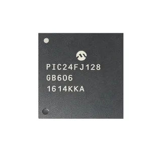
PIC24EP128MC206-E/MR - 16-Bit 60MIPS 128KB Flash Motor MCU | Microchip
MPN: PIC24EP128MC206-E/MR ✓ Hoạt độngPIC24EP128MC206-E/MR Tóm tắt
A 16-bit motor-control microcontroller is a specialized MCU that combines a 16-bit CPU core, deterministic PWM generators, and analog peripherals optimized for closed-loop control of BLDC, PMSM, ACIM, and stepper motors. In the broader taxonomy, it sits within microcontroller (MCU) -> 16-bit MCU -> digital signal controller (DSC) -> motor-control IC. The "EP" suffix denotes enhanced peripherals including high-speed PWM, quadrature encoder interfaces, and on-chip operational amplifiers that eliminate external analog signal conditioning.
Key features include 60 MIPS execution (16-bit modified-Harvard core with DSP engine), 128 KB self-programmable Flash (43K x 24), 16 KB SRAM, six 16-bit PWM channels with dedicated time bases, dual analog comparators, three on-chip operational amplifiers (10 MHz GBW), a 12-bit 1.1 Msps ADC with up to 16 input channels, and four UART/SPI/I2C peripherals. The 9x9 mm 64-pin VQFN package provides an exposed thermal pad for improved power dissipation.
Architecturally, the device uses Microchip's PIC24E core with a 16-bit data path, hardware multiply/divide, dual-port SRAM, and a peripheral engine supporting motor-control PWM with 7.14 ns resolution. The integrated op-amps can directly sense motor phase currents, reducing BOM and PCB area, while the high-speed ADC synchronizes with PWM for precise current sampling.
Typical applications include automotive HVAC blowers, electric water/oil pumps, BLDC and PMSM motor drives, ceiling and appliance fans, e-bike controllers, robotics actuators, and drone propulsion ESCs. The AEC-Q100 Grade 0 (-40C to +150C) rating supports underhood automotive deployments.
Design consideration: route the exposed pad (EP) to a continuous ground plane with at least 16 thermal vias for production reliability, and keep analog op-amp outputs short and isolated from PWM switching traces to prevent noise coupling into current-sense feedback.
This page synthesizes distributor pricing, drop-in alternatives within the PIC24EP family, application-specific companion ICs, and PCB layout notes that complement (but do not replace) the manufacturer datasheet and family reference manual.
Bộ thay thế dễ dàng lắp đặt cho PIC24EP128MC206-E/MR — cùng gói, chân-to-chân tương thích. Các bộ phận yêu cầu hàn PCB bị loại trừ.
Các biến thể trong loạt này
Các mẫu cùng loạt có thể lắp đặt dễ dàng tương thích với PIC24EP128MC206-E/MR (cùng hình factor và footprint) — khác nhau ở Operating Temperature, Package, ADC, Core Architecture, Maximum CPU Speed.
PIC24EP256MC206-I/MR
✅ Drop-In ⚠️ Thông số chưa được xác minhLiên hệ để biết giá
Xem tài liệu →PIC24EP64MC206-E/MR
✅ Drop-In ⚠️ Thông số chưa được xác minhLiên hệ để biết giá
Xem tài liệu →PIC24EP128MC206-I/MR
✅ Drop-In ⚠️ Thông số chưa được xác minhLiên hệ để biết giá
Xem tài liệu →PIC24EP128MC204-E/MV
✅ Drop-InLiên hệ để biết giá
Xem tài liệu →DSPIC33EP128MC206-E/MR
✅ Drop-InLiên hệ để biết giá
Xem tài liệu →PIC24EP128MC206-E/PT
✅ Drop-InLiên hệ để biết giá
Xem tài liệu →PIC24EP128MC206-E/MR Tỷ lệ tối đa & tính chất điện
| Core | PIC24E 16-bit dsPIC33/PIC24E DSC core |
| CPU Speed | 60 MIPS (70 MIPS instruction throughput) |
| Program Flash | 128 KB (43K x 24) |
| SRAM | 16 KB |
| Operating Voltage (Vdd) | 3.0 V to 3.6 V |
| Nhiệt độ hoạt động | -40C to +125C (extended) |
| PWM Channels | 6 x 16-bit with 7.14 ns resolution |
| On-Chip Op-Amps | 3 x 10 MHz GBW |
| ADC | 12-bit, up to 16 channels, 1.1 Msps |
| Analog Comparators | 2 |
| Quadrature Encoder Interface (QEI) | Yes |
| Communication Peripherals | 4 x UART/SPI/I2C (configurable) |
| Timers | 9 x 16-bit / 32-bit |
| DMA Channels | 8 |
| Hộp | 64-pin VQFN (MR) 9x9 mm with exposed pad |
| Kiểu lắp đặt | Surface Mount |
| AEC-Q100 | Qualified (automotive Grade 0 variant family) |
| Trạng thái RoHS | Compliant |
Cấu hình chân PIC24EP128MC206-E/MR
| Chân 1 | RP15/RB15 — Remappable I/O / PWM fault |
| Chân 2 | RP14/RB14 — Remappable I/O |
| Chân 3 | RP13/RB13 — Remappable I/O |
| Chân 4 | RP12/RB12 — Remappable I/O |
| Chân 5 | RP11/RB11 — Remappable I/O |
| Chân 6 | RP10/RB10 — Remappable I/O |
| Chân 7 | RP9/RB9 — Remappable I/O |
| Chân 8 | RP8/RB8 — Remappable I/O |
| Chân 9 | RP7/RB7 — Remappable I/O |
| Chân 10 | RP6/RB6 — Remappable I/O |
| Chân 11 | VDD — Core supply 3.3V |
| Chân 12 | VSS — Ground |
| Chân 13 | OSC1/RC12 — Crystal input or remappable I/O |
| Chân 14 | OSC2/RC15 — Crystal output or remappable I/O |
| Chân 15 | RP5/RB5 — Remappable I/O |
| Chân 16 | RP4/RB4 — Remappable I/O |
| Chân 17 | RP3/RB3 — Remappable I/O |
| Chân 18 | RP2/RB2 — Remappable I/O |
| Chân 19 | RP1/RB1 — Remappable I/O |
| Chân 20 | RP0/RB0 — Remappable I/O |
| Chân 21 | AVDD — Analog supply 3.3V |
| Chân 22 | AVSS — Analog ground |
| Chân 23 | AN0/RA0 — ADC input / analog I/O |
| Chân 24 | AN1/RA1 — ADC input / analog I/O |
| Chân 25 | AN2/RA2 — ADC input / analog I/O |
| Chân 26 | AN3/RA3 — ADC input / analog I/O |
| Chân 27 | AN4/RA4 — ADC input / analog I/O |
| Chân 28 | AN5/RA5 — ADC input / analog I/O |
| Chân 29 | VREF+/VDD — ADC voltage reference positive |
| Chân 30 | VREF-/VSS — ADC voltage reference negative |
| Chân 31 | AN6/RA6 — ADC input / analog I/O |
| Chân 32 | AN7/RA7 — ADC input / analog I/O |
| Chân 33 | AN8/RB0 — ADC input / remappable I/O |
| Chân 34 | AN9/RB1 — ADC input / remappable I/O |
| Chân 35 | AN10/RB2 — ADC input / remappable I/O |
| Chân 36 | AN11/RB3 — ADC input / remappable I/O |
| Chân 37 | AN12/RB4 — ADC input / remappable I/O |
| Chân 38 | AN13/RB5 — ADC input / remappable I/O |
| Chân 39 | AN14/RB6 — ADC input / remappable I/O |
| Chân 40 | AN15/RB7 — ADC input / remappable I/O |
| Chân 41 | OPA1IN/RA8 — Op-amp 1 input / analog I/O |
| Chân 42 | OPA1OUT/RA9 — Op-amp 1 output / analog I/O |
| Chân 43 | OPA2IN/RA10 — Op-amp 2 input / analog I/O |
| Chân 44 | OPA2OUT/RA11 — Op-amp 2 output / analog I/O |
| Chân 45 | OPA3IN/RA12 — Op-amp 3 input / analog I/O |
| Chân 46 | OPA3OUT/RA13 — Op-amp 3 output / analog I/O |
| Chân 47 | PWM1H/RE0 — PWM channel 1 high side output |
| Chân 48 | PWM1L/RE1 — PWM channel 1 low side output |
| Chân 49 | PWM2H/RE2 — PWM channel 2 high side output |
| Chân 50 | PWM2L/RE3 — PWM channel 2 low side output |
| Chân 51 | PWM3H/RE4 — PWM channel 3 high side output |
| Chân 52 | PWM3L/RE5 — PWM channel 3 low side output |
| Chân 53 | FLT32/RE6 — PWM fault input |
| Chân 54 | FLT33/RE7 — PWM fault input |
| Chân 55 | QEA/RD0 — Quadrature encoder A / remappable I/O |
| Chân 56 | QEB/RD1 — Quadrature encoder B / remappable I/O |
| Chân 57 | INDX/RD2 — Quadrature index / remappable I/O |
| Chân 58 | HOME/RD3 — Home input / remappable I/O |
| Chân 59 | MCLR — Master clear reset (active low) |
| Chân 60 | PGED2/RA0 — Programming data / remappable I/O |
| Chân 61 | PGEC2/RA1 — Programming clock / remappable I/O |
| Chân 62 | VDD — I/O supply 3.3V |
| Chân 63 | VSS — Ground |
| Chân 64 | EP — Exposed thermal pad (connect to GND) |
Ứng dụng tiêu biểu
PIC24EP128MC206-E/MR phù hợp cho 6 Áp dụngs: Automotive HVAC Blower Motor Control, Brushless DC (BLDC) Motor Drive for Pumps and Fans, PMSM / Servo Motor Controller for Robotics, Electric Water / Oil Pump Controller, Drone / UAV Electronic Speed Controller (ESC), Industrial Variable-Frequency Drive (VFD) Control Card.
Automotive HVAC Blower Motor Control
The PIC24EP128MC206-E/MR is a strong fit for automotive HVAC blower motor control because its 60 MIPS PIC24E core runs field-oriented control (FOC) algorithms in real time, while the three on-chip 10 MHz op-amps directly sense shunt-based phase currents without external analog signal conditioning. The six 16-bit PWM channels (7.14 ns edge resolution) drive a three-phase BLDC gate driver with center-aligned switching to minimize EMI in cabin audio bands. AEC-Q100 qualification with the -E extended -40C to +125C grade supports underhood air-handler locations. Design tip: route PWM outputs symmetrically to the gate driver, keep op-amp feedback traces short (<10 mm), and use a 4-layer PCB with a continuous ground pour under the QFN exposed pad tied to GND with at least 16 thermal vias.
Được đề xuất
Brushless DC (BLDC) Motor Drive for Pumps and Fans
For 24-48V BLDC pumps and fans, the PIC24EP128MC206-E/MR provides 128 KB Flash for sinusoidal commutation lookup tables, 16 KB SRAM for current-loop state variables, and a 12-bit 1.1 Msps ADC synchronized to PWM edges for precise current sampling. The integrated quadrature encoder interface (QEI) accepts Hall or encoder feedback for sensorless trapezoidal or sensored FOC control. Compared with 8-bit MCUs, the 60 MIPS throughput eliminates CPU bottlenecks at 30 kHz PWM frequencies. Place a 0.1 uF ceramic decoupling capacitor within 2 mm of each Vdd pin and keep the analog AGND and digital GND separated until they meet at the exposed pad for clean current-sense measurements.
Được đề xuất
PMSM / Servo Motor Controller for Robotics
The PIC24EP128MC206-E/MR supports PMSM servo applications where the DSP engine executes field-oriented control (FOC) in under 10 us per cycle. The hardware QEI decodes incremental A/B encoder signals up to 5 MHz, while the on-chip op-amps amplify low-voltage shunt signals before ADC sampling for torque-loop control. The 16 KB SRAM holds Clarke/Park transform state and SVPWM duty commands. With the same 64-pin VQFN footprint and same peripherals, design teams can migrate from prototype to production without changing schematics. For robotics, ensure the PCB layout follows 4-layer stackup with the QFN EP providing the thermal anchor for sustained motor-control compute loads.
Được đề xuất
Electric Water / Oil Pump Controller
In 12V/24V automotive electric water and oil pumps, the PIC24EP128MC206-E/MR's AEC-Q100 qualification, -40C to +125C operating range, and on-chip op-amps enable direct shunt-based current sensing without external components. The 60 MIPS PIC24E core closes PI speed and current loops deterministically at 20 kHz PWM. Hardware fault inputs (analog comparators and PWM fault pins) shut down the gate driver within 25 ns on overcurrent events, meeting ISO 26262 ASIL-A pump safety targets. Use 1% tolerance sense resistors rated for >2x steady-state current, and place an RC filter (100 ohm / 100 pF) on each op-amp output to attenuate switching noise before ADC sampling.
Được đề xuất
Drone / UAV Electronic Speed Controller (ESC)
Lightweight ESC designs benefit from the PIC24EP128MC206-E/MR's small 9x9 mm VQFN footprint, integrated op-amps for current sensing, and 6-PWM output that drives three-phase half-bridges at 48 kHz fast switching. With 60 MIPS throughput, fast sinusoidal commutation runs at 8-16 kHz with low loop latency for tight RPM control under varying load. The 16 KB SRAM holds timing-critical state without DMA stalls. Design tip: keep PWM traces short and impedance-controlled (50 ohm), use gate drivers with <50 ns propagation delay, and add TVS diodes on the DC bus to clamp inductive kickback. Add a back-EMF zero-cross detector using the on-chip analog comparators for sensorless startup.
Được đề xuất
Industrial Variable-Frequency Drive (VFD) Control Card
For industrial VFDs, the PIC24EP128MC206-E/MR provides 128 KB Flash for V/Hz and sensorless FOC firmware libraries, dual UART/SPI/I2C peripherals for Modbus RTU or SPI encoder feedback, and 6 PWM channels capable of driving IGBT gate drivers up to 20 kHz. The -40C to +125C extended grade handles enclosed cabinet environments. Replace legacy 8-bit MCUs with this PIC24E to add sensorless operation, dead-time compensation, and per-cycle current limiting. For VFD control cards, route analog feedback (CT/PT secondaries) through dedicated op-amp channels and add isolated gate-driver supplies (e.g., Si8271) between control and power stages.
Được đề xuất
Tóm tắt các sản phẩm được đề xuất
Dữ liệu tham khảo kỹ thuật cho PIC24EP128MC206-E/MR — so sánh, hướng dẫn thiết kế và thông tin tuân thủ.
Hướng dẫn chọn lựa
So sánh với các sản phẩm thay thế
| Tham số | Sản phẩm này | PIC24EP256MC206-I/MR | PIC24EP64MC206-E/MR | PIC24EP128MC206-I/MR | dsPIC33EP128MC206-E/MR |
|---|---|---|---|---|---|
| Package | 64-VQFN (MR) 9x9 mm with exposed pad | 64-VQFN (MR) 9x9 mm - same | 64-VQFN (MR) 9x9 mm - same | 64-VQFN (MR) 9x9 mm - same | 64-VQFN (MR) 9x9 mm - same |
| Brand | Microchip Technology | Microchip Technology | Microchip Technology | Microchip Technology | Microchip Technology |
| Core | PIC24E 16-bit | PIC24E 16-bit | PIC24E 16-bit | dsPIC33E 16-bit DSC (DSP engine) | |
| CPU Speed | 60 MIPS | 60 MIPS | 60 MIPS | 60 MIPS | |
| Flash | 128 KB | 256 KB (+100%) | 64 KB (-50%) | 128 KB (same) | 128 KB (same) |
| SRAM | 16 KB | 16 KB | 8 KB (-50%) | 16 KB | |
| Temperature Grade | -40C to +125C (E, extended) | -40C to +85C (I, industrial) | -40C to +125C (E, extended) | -40C to +85C (I, industrial) | |
| AEC-Q100 | Qualified (family) | Qualified (family) | Qualified (family) | Qualified (family) | |
| On-Chip Op-Amps | 3 x 10 MHz | 3 x 10 MHz | 3 x 10 MHz | 3 x 10 MHz | |
| PWM Channels | 6 x 16-bit | 6 x 16-bit | 6 x 16-bit | 6 x 16-bit |
Bảo phân biệt quan trọng
- Triple integrated on-chip op-amps eliminate external current-sense analog (vsPIC24EP128GP206 (no MC op-amps))
- AEC-Q100 qualified with extended -40C to +125C grade (vsPIC24EP128GP206 industrial grade)
- Six 16-bit PWM with 7.14 ns edge resolution (vsPIC24EP128MC204 (4 PWM channels))
Ghi chú thiết kế
The 64-pin 9x9 mm VQFN package dissipates motor-control compute heat through the exposed thermal pad. Connect EP to a continuous ground plane on the top layer with at least 16 thermal vias (0.3 mm drill, 0.5 mm pad) to the inner ground plane. At 60 MIPS full load with sustained PWM activity, junction temperature can rise 25-35 C above ambient without a thermal via array. For underhood automotive deployments (-40C to +125C ambient), the thermal via count should be increased to 20+ vias to maintain junction below 150 C.
Route analog op-amp inputs (OPA1IN/OPA2IN/OPA3IN) and current-shunt traces directly to the shunt resistors with short (<10 mm) and symmetric differential routing. Place 100 ohm / 100 pF RC filters on op-amp outputs to attenuate PWM switching noise before ADC sampling. Keep analog ground (AVSS) and digital ground (VSS) separated until they merge at the EP ground pour. Place 0.1 uF ceramic decoupling capacitors within 2 mm of every VDD/AVDD pin and add a single 10 uF bulk capacitor near the IC supply input.
Do not float the MCLR pin - tie it to VDD through a 10 kohm pull-up resistor to avoid unintended resets. Configure unused PWM outputs as GPIO outputs driven low to prevent shoot-through in the gate driver. Verify ADC sampling is synchronized to PWM edges in PWM-trigger mode to avoid sampling during switching transients. Do not exceed the absolute maximum VDD of 3.6 V - using a 5V supply will damage the MCU. Always validate the BOR (brown-out reset) threshold setting matches the system voltage profile.
PWM outputs driving external gate drivers should use 50 ohm characteristic impedance traces and be length-matched within 5 mm between high-side and low-side pairs of the same channel to prevent timing skew. Place a series ferrite bead or 10 ohm resistor near the MCU PWM pin to dampen transmission-line ringing when driving capacitive gate loads. For QEI inputs from motor encoders, route A/B/INDEX signals as a matched differential or guarded triplet to reject common-mode motor switching noise.
Thông tin tuân thủ
AEC-Q100 qualified per Microchip PIC24EP family qualification reports. RoHS and lead-free confirmed by Microchip product page and LCSC listing. Halogen-free status not explicitly stated - set to unknown per data authenticity rules.