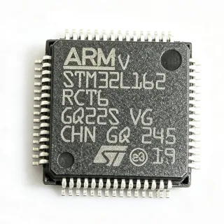
STM32F051R8T6 - 48MHz Cortex-M0 MCU, 64KB Flash | ST
MPN: STM32F051R8T6 ✓ Hoạt độngSTM32F051R8T6 Tóm tắt
A microcontroller (MCU) integrates a processor core, non-volatile memory, SRAM, and a rich set of peripherals onto a single silicon die, forming the lowest tier of the computing hierarchy: transistor -> logic gate -> processor core -> microcontroller -> embedded system. Within STMicroelectronics' portfolio, the STM32F0 entry-level series sits below the mainstream STM32F1/F4 families and provides Cortex-M0 cost efficiency while retaining STM32 tooling, peripheral architecture, and software ecosystem compatibility.
Key features of the STM32F051R8T6 include 11 timers covering basic, general-purpose, and advanced (motor-control) functions, a 12-bit 1 Msps ADC, a 12-bit DAC, up to 55 GPIO lines, and communication interfaces spanning USART, SPI, I2C, and CEC. A CRC calculation unit, programmable watchdogs, and POR/PDR reset circuitry improve design robustness. Supply voltage spans 2.0V to 3.6V, simplifying integration into battery- and USB-adjacent designs.
Technically, the Cortex-M0 core executes Thumb instruction subset code with a 32-bit datapath and a nested vectored interrupt controller (NVIC) delivering deterministic low-latency interrupts. The embedded Flash supports in-system programming via USART, while the flexible clock tree accepts an internal 8 MHz HSI or external crystal sources up to 48 MHz system frequency.
Typical applications include industrial automation sensors and actuators, consumer appliances, motor control with the advanced timers, IoT sensor nodes, and system auxiliary control functions.
Designers should budget SRAM carefully: 8 KB is ample for bare-metal control loops but limits large buffers or complex stacks; enable hardware CRC and DMA offload to free CPU cycles.
This page adds value beyond the manufacturer datasheet by consolidating verified distributor specifications, drop-in alternatives, cross-brand substitution guidance, and practical design notes for the STM32F051R8T6.
Bộ thay thế dễ dàng lắp đặt cho STM32F051R8T6 — cùng gói, chân-to-chân tương thích. Các bộ phận yêu cầu hàn PCB bị loại trừ.
Các biến thể trong loạt này
Các mẫu cùng loạt có thể lắp đặt dễ dàng tương thích với STM32F051R8T6 (cùng hình factor và footprint) — khác nhau ở Package, ADC, Communication Interfaces, Timers, Flash Memory.
STM32F051R8T7
✅ Drop-In📋 Tham chiếu thay thế (không có trong danh mục)
STM32F051R6T6
✅ Drop-In ⚠️ Thông số chưa được xác minhLiên hệ để biết giá
Xem tài liệu →STM32F042R6T6
✅ Drop-In ⚠️ Thông số chưa được xác minh📋 Tham chiếu thay thế (không có trong danh mục)
STM32F031R6T6
✅ Drop-In ⚠️ Thông số chưa được xác minh📋 Tham chiếu thay thế (không có trong danh mục)
GD32F130R8T6
✅ Drop-In📋 Tham chiếu thay thế (không có trong danh mục)
STM32F051R8T6 Tỷ lệ tối đa & tính chất điện
| Core | ARM Cortex-M0, 32-bit |
| Maximum CPU Frequency | 48 MHz |
| Flash Memory | 64 KB |
| SRAM | 8 KB |
| Supply Voltage Range | 2.0 V to 3.6 V |
| GPIO Count | 55 I/O |
| Timers | 11 (basic, general-purpose, advanced) |
| ADC | 12-bit, 1 Msps |
| DAC | 12-bit |
| Communication Interfaces | USART, SPI, I2C, CEC |
| CRC Unit | Yes |
| Reset | POR/PDR (power-on / power-down reset) |
| Oscillator Type | Internal (HSI) and external |
| Hộp | LQFP-64 |
| Kiểu lắp đặt | Surface Mount |
| Program Memory Type | FLASH |
| Trạng thái RoHS | Compliant |
Cấu hình chân STM32F051R8T6
| Chân 1 | VBAT — Backup battery supply for RTC |
| Chân 2 | PC13 — GPIO / RTC functions |
| Chân 3 | PC14-OSC32_IN — GPIO / 32.768 kHz oscillator input |
| Chân 4 | PC15-OSC32_OUT — GPIO / 32.768 kHz oscillator output |
| Chân 5 | PH0-OSC_IN — Main oscillator input |
| Chân 6 | PH1-OSC_OUT — Main oscillator output |
| Chân 7 | NRST — System reset (active low) |
| Chân 8 | PC0 — GPIO / ADC input |
| Chân 9 | PC1 — GPIO / ADC input |
| Chân 10 | PC2 — GPIO / ADC input |
| Chân 11 | PC3 — GPIO / ADC input |
| Chân 12 | VSSA — Analog ground |
| Chân 13 | VDDA — Analog supply |
| Chân 14 | PA0 — GPIO / ADC / wake-up |
| Chân 15 | PA1 — GPIO / ADC |
| Chân 16 | PA2 — GPIO / USART2_TX / ADC |
| Chân 17 | PA3 — GPIO / USART2_RX / ADC |
| Chân 18 | PA4 — GPIO / SPI1_NSS / DAC_OUT1 |
| Chân 19 | PA5 — GPIO / SPI1_SCK / DAC_OUT2 |
| Chân 20 | PA6 — GPIO / SPI1_MISO / ADC |
| Chân 21 | PA7 — GPIO / SPI1_MOSI / ADC |
| Chân 22 | PC4 — GPIO / ADC input |
| Chân 23 | PC5 — GPIO / ADC input |
| Chân 24 | PB0 — GPIO / ADC input |
| Chân 25 | PB1 — GPIO / ADC input |
| Chân 26 | PB2 — GPIO / BOOT1 |
| Chân 27 | PB10 — GPIO / I2C2_SCL / USART3_TX |
| Chân 28 | PB11 — GPIO / I2C2_SDA / USART3_RX |
| Chân 29 | VSS_1 — Ground |
| Chân 30 | VDD_1 — Digital supply |
| Chân 31 | PB12 — GPIO / SPI2_NSS |
| Chân 32 | PB13 — GPIO / SPI2_SCK |
| Chân 33 | PB14 — GPIO / SPI2_MISO |
| Chân 34 | PB15 — GPIO / SPI2_MOSI |
| Chân 35 | PC6 — GPIO |
| Chân 36 | PC7 — GPIO |
| Chân 37 | PC8 — GPIO |
| Chân 38 | PC9 — GPIO |
| Chân 39 | PA8 — GPIO / USART1_CK / MCO |
| Chân 40 | PA9 — GPIO / USART1_TX |
| Chân 41 | PA10 — GPIO / USART1_RX |
| Chân 42 | PA11 — GPIO / CEC / TIM1_CH4 |
| Chân 43 | PA12 — GPIO / CEC |
| Chân 44 | PA13 — GPIO / SWDIO (debug) |
| Chân 45 | VSS_2 — Ground |
| Chân 46 | VDD_2 — Digital supply |
| Chân 47 | PA14 — GPIO / SWCLK (debug) |
| Chân 48 | PA15 — GPIO / SPI1_NSS |
| Chân 49 | PC10 — GPIO / USART3_TX |
| Chân 50 | PC11 — GPIO / USART3_RX |
| Chân 51 | PC12 — GPIO / USART3_CK |
| Chân 52 | PD2 — GPIO / USART3_RX |
| Chân 53 | PB3 — GPIO / SPI1_SCK / SWO |
| Chân 54 | PB4 — GPIO / SPI1_MISO |
| Chân 55 | PB5 — GPIO / SPI1_MOSI / I2C1_SMBA |
| Chân 56 | PB6 — GPIO / I2C1_SCL / USART1_TX |
| Chân 57 | PB7 — GPIO / I2C1_SDA / USART1_RX |
| Chân 58 | BOOT0 — Boot mode selection |
| Chân 59 | PB8 — GPIO / I2C1_SCL / CEC |
| Chân 60 | PB9 — GPIO / I2C1_SDA |
| Chân 61 | VSS_3 — Ground |
| Chân 62 | VDD_3 — Digital supply |
| Chân 63 | PB8/PB9-BOOT — GPIO / boot pin alternate bonding |
| Chân 64 | VDDIO2 — I/O supply domain 2 |
Ứng dụng tiêu biểu
STM32F051R8T6 phù hợp cho 6 Áp dụngs: Industrial Automation Sensors and Actuators, Low-Voltage Motor Control, IoT Sensor Nodes, Consumer Appliances and White Goods, USB-Adjacent and CEC Consumer Electronics, System Management and Auxiliary Control.
Industrial Automation Sensors and Actuators
The STM32F051R8T6 fits industrial sensing and actuation nodes because its 12-bit 1 Msps ADC digitizes analog sensor channels with adequate resolution, and 55 GPIO plus USART/SPI/I2C interfaces integrate encoders, displays, and field-bus bridges. The 2.0V-3.6V tolerant supply with POR/PDR reset gives robust power-up behavior in noisy factory environments. In typical use the MCU runs a bare-metal control loop reading sensor data via DMA-driven ADC conversions, applying filtering, and driving relays or actuators through general-purpose timers. The hardware CRC unit validates communication frames without CPU overhead. The constraint to plan for is 8 KB SRAM - keep buffering shallow and avoid large protocol stacks.
Được đề xuất
Low-Voltage Motor Control
For BLDC/DC fan and pump motor control, the STM32F051R8T6 offers advanced-control timers with complementary PWM outputs and dead-time insertion - precisely the features a three-phase inverter bridge needs. The synchronized 12-bit ADC samples phase current shunts mid-PWM-cycle, supporting sensorless back-EMF commutation or hall-sensored control on the 48 MHz Cortex-M0 core. ST application examples target exactly this configuration within the STM32F0 ecosystem. Designers must respect the 8 KB SRAM budget when implementing observers, and should verify ADC injection-sampling timing in the reference manual before finalizing firmware, since peripheral density is moderate on this entry-level device.
Được đề xuất
IoT Sensor Nodes
Battery-adjacent IoT nodes benefit from the STM32F051R8T6's 2.0V operation - the MCU keeps running as a battery discharges - while low run power and multiple low-power modes extend field life. On-chip SPI/I2C interfaces connect RF modules and MEMS sensors, and the 12-bit ADC monitors battery voltage and analog probes. A typical topology pairs the MCU with a sub-GHz or BLE radio module over UART, waking on sensor threshold interrupts via EXTI lines. The key trade-off is the absence of larger SRAM for TLS stacks, so designs needing heavy cryptography should either externalize connectivity intelligence to the module or select a higher-memory pin-compatible STM32.
Được đề xuất
Consumer Appliances and White Goods
The STM32F051R8T6 suits appliance control boards: 55 GPIO drive keypads, indicators, and relays, while 11 timers manage touch-sensing, buzzer tones, PWM loads, and watchdog supervision. The on-chip CEC interface supports HDMI-CEC control paths in AV appliances. Its 3.3V operation and internal oscillator remove the cost of external crystals in non-timing-critical products, and the CRC unit plus POR/PDR improve resilience against mains-borne transients. Compliance-oriented appliance designs commonly pair this MCU with isolated AC-line sensing. Firmware is developed in STM32CubeIDE using the standard peripheral model, keeping certification rework low when migrating within the STM32F0 family.
Được đề xuất
USB-Adjacent and CEC Consumer Electronics
With a 2.0V-3.6V supply and CEC support, the STM32F051R8T6 integrates into consumer electronics subsystems that need a co-processor for button decoding, IR/CEC protocol handling, and power sequencing under main-SoC control. USART and I2C links to the host are straightforward, and the 64 KB Flash accommodates protocol stacks plus OTA-style firmware field updates implemented as user bootloaders. Note that this exact part lacks a native USB controller; for designs that must enumerate USB directly, the pin-compatible STM32F042R6T6 alternative adds a USB device peripheral while retaining the LQFP-64 footprint, making the migration a low-risk drop-in.
Được đề xuất
System Management and Auxiliary Control
As a system-management co-processor, the STM32F051R8T6 supervises fans, power rails, and front panels in networking and instrumentation equipment. Its 12-bit ADC reads thermistors and rail voltages, PWM timers drive fan channels, and USART links report telemetry to a host CPU or FPGA board. The deterministic Cortex-M0 NVIC keeps monitoring loops responsive even under interrupt storms, and watchdog timers guarantee recovery from host crashes. When used alongside XAIPART FPGA products such as the Intel/Altera MAX 10 family, the MCU handles slow housekeeping while the FPGA manages high-speed logic - a proven architecture for cost-optimized embedded platforms.
Được đề xuất
Tóm tắt các sản phẩm được đề xuất
Dữ liệu tham khảo kỹ thuật cho STM32F051R8T6 — so sánh, hướng dẫn thiết kế và thông tin tuân thủ.
Hướng dẫn chọn lựa
So sánh với các sản phẩm thay thế
| Tham số | Sản phẩm này | STM32F051R8T7 | STM32F051R6T6 | STM32F042R6T6 | GD32F130R8T6 |
|---|---|---|---|---|---|
| Package | LQFP-64 | LQFP-64 - same | LQFP-64 - same | LQFP-64 - same | LQFP-64 - same |
| Brand | STMicroelectronics | STMicroelectronics | STMicroelectronics | STMicroelectronics | GigaDevice |
| Core / Max Frequency | ARM Cortex-M0, 48 MHz | Cortex-M0, 48 MHz | Cortex-M0, 48 MHz | Cortex-M0, 48 MHz | Cortex-M0, up to 72 MHz |
| Flash Memory | 64 KB | 64 KB | 32 KB | 32 KB | 64 KB |
| Supply Voltage | 2.0 V - 3.6 V | 2.0 V - 3.6 V | 2.0 V - 3.6 V | 2.0 V - 3.6 V | 2.6 V - 3.6 V |
Bảo phân biệt quan trọng
- Full 64 KB Flash within the pin-compatible family (vsSTM32F051R6T6)
- Guaranteed ST datasheet compatibility (vsGD32F130R8T6)
- Advanced timers with complementary PWM and dead-time (vsSTM32F031R6T6)
- Trade-off: no native USB controller (vsSTM32F042R6T6)
Ghi chú thiết kế
Decouple each VDD pin (pins 30, 46, 62/64 domain) with a 100 nF ceramic capacitor placed within 3 mm of the pin, plus one 4.7 uF bulk capacitor near the regulator output. The VDDA/VSSA pair (pins 13/12) requires a separate ferrite bead and 1 uF + 10 nF filtering to preserve the 12-bit ADC's effective resolution; injecting switching-regulator ripple into VDDA is the most common cause of ADC noise complaints on STM32F0 boards.
The LQFP-64 thermal pad is absent, so heat exits through the leads - normal for the sub-100 mW dissipation of this MCU. Instead, prioritize trace fan-out: route the SWDIO (pin 44) and SWCLK (pin 47) debug lines to a 4-pin header before final layout, because rework to access them later is difficult. Keep BOOT0 (pin 58) tied through a 10 kOhm pulldown to GND with a test point for firmware recovery via the built-in USART bootloader.
Do not assume flash wait-state timing identical across the family: when cross-brand substituting with GigaDevice GD32F130R8T6, flash zero-wait-state behavior differs and tight timing loops calibrated on the STM32F051R8T6 at 48 MHz will shift. Also confirm the operating temperature requirement before choosing T6 over the T7 industrial grade - consumer grade T6 parts are not specified for extended industrial ambients, and field failures in sealed enclosures often trace to this suffix-level mismatch.
Estimated: with a 48 MHz core clock the GPIO edges are fast enough (typically low-ns class) to generate noticeable ringing on un-terminated ribbon-cable loads; add 22-33 Ohm series resistors on lines leaving the board and on USART TX/RX to external modules. This simple practice, taken from ST EME (electromagnetic compatibility) application guidance for STM32 families, reduces radiated emissions at low development cost.
Thông tin tuân thủ
RoHS compliance per STMicroelectronics standard product listing for STM32F0 series. REACH, halogen-free, and conflict-minerals status not stated in provided web data - verify on st.com product compliance portal.