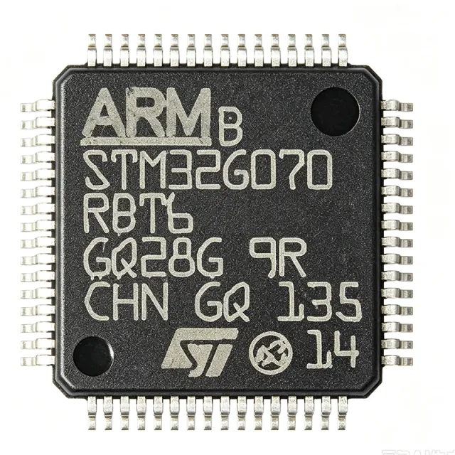
STM32G070RBT6 - 128KB Flash ARM Cortex-M0+ MCU | STMicroelectronics
MPN: STM32G070RBT6 ✓ Hoạt độngSTM32G070RBT6 Tóm tắt
A microcontroller (MCU) is a compact integrated circuit designed to govern a specific operation in an embedded system. It contains a processor core, memory, and programmable input/output peripherals on a single chip. The STM32G070RBT6 belongs to the STM32G0 series, which is part of the broader STM32 family of 32-bit ARM Cortex-M microcontrollers. This hierarchy places it within the embedded processing domain, where it serves as the central control unit for a wide range of applications.
Key features include a 12-bit ADC with up to 19 channels, multiple timers (including advanced-control timers), and a rich set of communication interfaces such as I2C, SPI, USART, and CAN. The device also integrates a DMA controller, a real-time clock (RTC), and a variety of low-power modes, making it suitable for power-sensitive applications. The LQFP64 package provides a compact footprint with 51 GPIOs, enabling flexible system design.
The STM32G070RBT6 is built on a high-performance ARM Cortex-M0+ core with a single-cycle multiplier and a nested vectored interrupt controller (NVIC). It includes a memory protection unit (MPU) for enhanced security and reliability. The device supports a wide operating temperature range of -40°C to +85°C, making it suitable for industrial environments. Its low-power design includes sleep, stop, and standby modes, with typical current consumption in the microampere range.
Typical applications include industrial control systems, home automation, consumer electronics, and IoT devices. The rich peripheral set and low power consumption make it ideal for sensor hubs, motor control, and communication gateways. The CAN interface is particularly useful for automotive and industrial networking applications.
When designing with this MCU, ensure proper decoupling of the power supply pins and consider the use of an external crystal for accurate timing. The device supports in-circuit programming and debugging via SWD, facilitating development and production programming.
This page synthesizes distributor pricing, drop-in alternatives, and practical design notes not found in the STMicroelectronics datasheet, providing a comprehensive resource for engineers evaluating the STM32G070RBT6.
Bộ thay thế dễ dàng lắp đặt cho STM32G070RBT6 — cùng gói, chân-to-chân tương thích. Các bộ phận yêu cầu hàn PCB bị loại trừ.
Các biến thể trong loạt này
Các mẫu cùng loạt có thể lắp đặt dễ dàng tương thích với STM32G070RBT6 (cùng hình factor và footprint) — khác nhau ở Communication Interfaces, Flash Memory, Package.
STM32G071RBT6
✅ Drop-In ⚠️ Thông số chưa được xác minhLiên hệ để biết giá
Xem tài liệu →STM32G070RBT6TR
✅ Drop-In ⚠️ Thông số chưa được xác minh📋 Tham chiếu thay thế (không có trong danh mục)
STM32G070RBT6Q
✅ Drop-In ⚠️ Thông số chưa được xác minh📋 Tham chiếu thay thế (không có trong danh mục)
STM32G071R8T6
✅ Drop-In ⚠️ Thông số chưa được xác minh📋 Tham chiếu thay thế (không có trong danh mục)
STM32G070RBT6 Tỷ lệ tối đa & tính chất điện
| Core | ARM Cortex-M0+ |
| Maximum Frequency | 64 MHz |
| Flash Memory | 128 KB |
| SRAM | 36 KB |
| Supply Voltage Range | 2.0 V to 3.6 V |
| Hộp | LQFP64 |
| GPIO Pins | 51 |
| ADC | 12-bit, 19 channels |
| Timers | Advanced-control timers, general-purpose timers, basic timers |
| Communication Interfaces | I2C, SPI, USART, CAN |
| DMA | Yes |
| RTC | Yes |
| Low-Power Modes | Sleep, Stop, Standby |
| Khoảng nhiệt độ hoạt động | -40°C to +85°C |
| Debug Interface | SWD |
| Trạng thái RoHS | Compliant |
Cấu hình chân STM32G070RBT6
| Chân 1 | VBAT — Battery backup supply for RTC |
| Chân 2 | PC13 — GPIO / RTC tamper / WKUP2 |
| Chân 3 | PC14 — GPIO / OSC32_IN |
| Chân 4 | PC15 — GPIO / OSC32_OUT |
| Chân 5 | PF0 — GPIO / OSC_IN |
| Chân 6 | PF1 — GPIO / OSC_OUT |
| Chân 7 | NRST — Reset (active low) |
| Chân 8 | VDD — Digital power supply |
| Chân 9 | VSS — Ground |
| Chân 10 | PA0 — GPIO / ADC_IN0 / WKUP1 |
| Chân 11 | PA1 — GPIO / ADC_IN1 |
| Chân 12 | PA2 — GPIO / USART2_TX / ADC_IN2 |
| Chân 13 | PA3 — GPIO / USART2_RX / ADC_IN3 |
| Chân 14 | PA4 — GPIO / SPI1_NSS / DAC_OUT1 |
| Chân 15 | PA5 — GPIO / SPI1_SCK / DAC_OUT2 |
| Chân 16 | PA6 — GPIO / SPI1_MISO / TIM3_CH1 |
| Chân 17 | PA7 — GPIO / SPI1_MOSI / TIM3_CH2 |
| Chân 18 | PB0 — GPIO / ADC_IN8 / TIM3_CH3 |
| Chân 19 | PB1 — GPIO / ADC_IN9 / TIM3_CH4 |
| Chân 20 | PB2 — GPIO / BOOT1 |
| Chân 21 | PB10 — GPIO / I2C2_SCL / USART3_TX |
| Chân 22 | PB11 — GPIO / I2C2_SDA / USART3_RX |
| Chân 23 | PB12 — GPIO / SPI2_NSS / I2S2_WS |
| Chân 24 | PB13 — GPIO / SPI2_SCK / I2S2_CK |
| Chân 25 | PB14 — GPIO / SPI2_MISO / I2S2_MCK |
| Chân 26 | PB15 — GPIO / SPI2_MOSI / I2S2_SD |
| Chân 27 | PC6 — GPIO / TIM3_CH1 / USART6_TX |
| Chân 28 | PC7 — GPIO / TIM3_CH2 / USART6_RX |
| Chân 29 | PC8 — GPIO / TIM3_CH3 / USART6_CK |
| Chân 30 | PC9 — GPIO / TIM3_CH4 / I2C3_SDA |
| Chân 31 | PA8 — GPIO / MCO / TIM1_CH1 |
| Chân 32 | PA9 — GPIO / USART1_TX / TIM1_CH2 |
| Chân 33 | PA10 — GPIO / USART1_RX / TIM1_CH3 |
| Chân 34 | PA11 — GPIO / CAN_RX / USART1_CTS |
| Chân 35 | PA12 — GPIO / CAN_TX / USART1_RTS |
| Chân 36 | PA13 — GPIO / SWDIO |
| Chân 37 | PA14 — GPIO / SWCLK |
| Chân 38 | PA15 — GPIO / SPI1_NSS / TIM2_CH1 |
| Chân 39 | PB3 — GPIO / SPI1_SCK / TIM2_CH2 |
| Chân 40 | PB4 — GPIO / SPI1_MISO / TIM3_CH1 |
| Chân 41 | PB5 — GPIO / SPI1_MOSI / TIM3_CH2 |
| Chân 42 | PB6 — GPIO / I2C1_SCL / USART1_TX |
| Chân 43 | PB7 — GPIO / I2C1_SDA / USART1_RX |
| Chân 44 | PB8 — GPIO / I2C1_SCL / CAN_RX |
| Chân 45 | PB9 — GPIO / I2C1_SDA / CAN_TX |
| Chân 46 | VDD — Digital power supply |
| Chân 47 | VSS — Ground |
| Chân 48 | PC10 — GPIO / USART4_TX / I2C3_SCL |
| Chân 49 | PC11 — GPIO / USART4_RX / I2C3_SDA |
| Chân 50 | PC12 — GPIO / USART5_TX / I2C3_SCL |
| Chân 51 | PD2 — GPIO / USART5_RX / TIM1_ETR |
| Chân 52 | VDD — Digital power supply |
| Chân 53 | VSS — Ground |
| Chân 54 | PC0 — GPIO / ADC_IN10 |
| Chân 55 | PC1 — GPIO / ADC_IN11 |
| Chân 56 | PC2 — GPIO / ADC_IN12 |
| Chân 57 | PC3 — GPIO / ADC_IN13 |
| Chân 58 | PC4 — GPIO / ADC_IN14 |
| Chân 59 | PC5 — GPIO / ADC_IN15 |
| Chân 60 | PB12 — GPIO / SPI2_NSS / I2S2_WS |
| Chân 61 | PB13 — GPIO / SPI2_SCK / I2S2_CK |
| Chân 62 | PB14 — GPIO / SPI2_MISO / I2S2_MCK |
| Chân 63 | PB15 — GPIO / SPI2_MOSI / I2S2_SD |
| Chân 64 | VDD — Digital power supply |
Ứng dụng tiêu biểu
STM32G070RBT6 phù hợp cho 6 Áp dụngs: Industrial Control Systems, Home Automation, Consumer Electronics, IoT Devices, Motor Control, Communication Gateways.
Industrial Control Systems
The STM32G070RBT6 is well-suited for industrial control systems due to its robust set of timers, 12-bit ADC, and CAN interface. Its 64 MHz Cortex-M0+ core provides sufficient processing power for real-time control loops, while the wide operating temperature range (-40°C to +85°C) ensures reliability in harsh factory environments. The device can handle multiple sensor inputs, drive actuators, and communicate over industrial networks such as CANopen or Modbus. Its low-power modes help reduce energy consumption in always-on monitoring applications. The LQFP64 package with 51 GPIOs allows flexible interfacing with external components, and the SWD debug interface simplifies firmware development and field updates.
Được đề xuất
Home Automation
In home automation, the STM32G070RBT6 serves as a central controller for smart home devices. Its low-power modes are ideal for battery-powered sensors and actuators, while the rich communication interfaces (I2C, SPI, USART) enable connectivity with various sensors, displays, and wireless modules. The 12-bit ADC can read analog sensors like temperature and light, and the GPIOs can control relays or LEDs. The device's small LQFP64 footprint fits into compact smart home devices, and its 128KB Flash provides ample space for application code. The RTC allows scheduling and time-stamping events, and the DMA controller offloads data transfer tasks from the CPU, improving efficiency.
Được đề xuất
Consumer Electronics
The STM32G070RBT6 is used in consumer electronics such as smart appliances, wearables, and gaming peripherals. Its 64 MHz performance handles user interface tasks, sensor processing, and communication protocols. The device's low power consumption extends battery life in portable devices, and its multiple timers generate precise PWM signals for motor control or LED dimming. The 12-bit ADC interfaces with touch sensors or analog joysticks, and the USART/SPI interfaces connect to Bluetooth or display modules. The LQFP64 package is cost-effective for mass production, and the wide supply voltage range (2.0V to 3.6V) accommodates various battery chemistries.
Được đề xuất
IoT Devices
For IoT devices, the STM32G070RBT6 provides a balanced combination of processing power, memory, and connectivity. Its 128KB Flash and 36KB SRAM support complex firmware, including communication stacks and sensor fusion algorithms. The device's low-power modes are crucial for battery-powered IoT nodes, with standby current in the microampere range. The CAN interface is useful for industrial IoT gateways, while I2C/SPI/USART connect to a wide range of sensors and wireless modules. The 12-bit ADC enables direct sensor interfacing, and the DMA controller efficiently handles data streaming. The device's security features, including the MPU, help protect against unauthorized access.
Được đề xuất
Motor Control
The STM32G070RBT6 is well-suited for motor control applications, such as brushless DC (BLDC) motors and stepper motors. Its advanced-control timers generate high-resolution PWM signals for driving motor phases, and the 12-bit ADC samples current and voltage feedback for closed-loop control. The device's 64 MHz core executes control algorithms like FOC (Field-Oriented Control) with sufficient speed. The CAN interface allows integration into industrial motor control networks. The LQFP64 package provides enough GPIOs for encoder interfaces and fault detection circuits. The device's robust design and wide temperature range make it reliable in demanding motor control environments.
Được đề xuất
Communication Gateways
The STM32G070RBT6 can serve as a communication gateway, bridging different protocols such as CAN, UART, SPI, and I2C. Its multiple USARTs and SPI interfaces allow simultaneous connection to various devices, while the CAN interface enables industrial network integration. The device's 128KB Flash can store protocol conversion firmware, and the DMA controller facilitates high-throughput data transfer without CPU intervention. The low-power modes are beneficial for gateways that need to conserve energy during idle periods. The LQFP64 package offers enough pins for multiple interface connectors, and the device's reliability ensures stable operation in always-on gateway applications.
Được đề xuất
Tóm tắt các sản phẩm được đề xuất
Dữ liệu tham khảo kỹ thuật cho STM32G070RBT6 — so sánh, hướng dẫn thiết kế và thông tin tuân thủ.
Hướng dẫn chọn lựa
So sánh với các sản phẩm thay thế
| Tham số | Sản phẩm này | STM32G071RBT6 | STM32G070RBT6TR | STM32G070RBT6Q | STM32G071R8T6 |
|---|---|---|---|---|---|
| Package | LQFP64 | LQFP64 - same | LQFP64 - same | LQFP64 - same | LQFP64 - same |
| Brand | STMicroelectronics | STMicroelectronics | STMicroelectronics | STMicroelectronics | STMicroelectronics |
| Core | ARM Cortex-M0+ | ARM Cortex-M0+ | ARM Cortex-M0+ | ARM Cortex-M0+ | ARM Cortex-M0+ |
| Maximum Frequency | 64 MHz | 64 MHz | 64 MHz | 64 MHz | 64 MHz |
| Flash Memory | 128 KB | 128 KB | 128 KB | 128 KB | 64 KB |
| SRAM | 36 KB | 36 KB | 36 KB | 36 KB | 36 KB |
| ADC | 12-bit, 19 channels | 12-bit, 19 channels | 12-bit, 19 channels | 12-bit, 19 channels | 12-bit, 19 channels |
| DAC | No | Yes | No | No | Yes |
| Communication Interfaces | I2C, SPI, USART, CAN | I2C, SPI, USART, CAN | I2C, SPI, USART, CAN | I2C, SPI, USART, CAN | I2C, SPI, USART, CAN |
Bảo phân biệt quan trọng
- Higher Flash memory (128KB) compared to some variants (vsSTM32G071R8T6)
- Lower cost than STM32G071RBT6 (vsSTM32G071RBT6)
- Pin-compatible with STM32G071RBT6 (vsSTM32G071RBT6)
Ghi chú thiết kế
Ensure proper decoupling of the VDD pins with 100nF ceramic capacitors placed as close as possible to each VDD pin. Additionally, use a 4.7uF bulk capacitor on the main power rail. The STM32G070RBT6 operates from 2.0V to 3.6V, so verify that the power supply stays within this range during all operating conditions, including transients.
For the LQFP64 package, ensure adequate copper pour for the ground pins to minimize inductance. Place the decoupling capacitors on the same side of the PCB as the MCU, close to the pins. If using an external crystal, place it near the OSC_IN/OSC_OUT pins (PF0/PF1) with proper load capacitors as specified in the datasheet. Keep high-speed communication lines (SPI, USART) away from noisy power traces.
Do not leave the NRST pin floating; connect it to VDD through a 100nF capacitor and a 10kOhm pull-up resistor. Ensure the BOOT0 pin is properly configured for the desired boot mode. When using the ADC, avoid exceeding the maximum input voltage (VDD+0.3V) on any analog pin. Also, note that the STM32G070RBT6 does not have a DAC, so if your application requires analog output, consider the STM32G071RBT6 instead.
Thông tin tuân thủ
RoHS compliant per STMicroelectronics product page. Not AEC-Q100 qualified; for automotive, consider STM32G0 series with AEC-Q100 option.