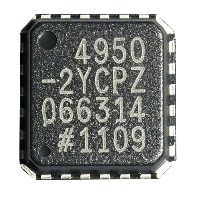
ADA4950-2YCPZ - Dual Differential ADC Driver | Analog Devices
MPN: ADA4950-2YCPZ ✓ 啟用中| 數量 | 單價 | 小計 |
|---|---|---|
| 1 | $8.58 | $8.58 |
| 10 | $7.72 | $77.20 |
| 100 | $6.23 | $623.00 |
| 500 | $5.5 | $2,750.00 |
| 1,000 | $4.95 | $4,950.00 |
ADA4950-2YCPZ 概覽
A differential amplifier is an electronic amplifier that amplifies the difference between two input voltages while rejecting common-mode signals. In the context of ADC driving, a differential amplifier converts a single-ended signal to a differential signal or buffers a differential signal, providing the necessary drive strength and level shifting to interface with high-performance analog-to-digital converters. The ADA4950-2 is specifically optimized for this role, offering low noise, low distortion, and high bandwidth to preserve signal integrity.
Key features of the ADA4950-2 include a -3 dB bandwidth of 1.35 GHz (gain = 1), a slew rate of 2900 V/µs, and a low input voltage noise of 2.2 nV/√Hz. The device provides a differential output with a common-mode voltage set by an internal reference, simplifying interface to ADCs. It also features a power-down mode to conserve energy when not in use. The on-chip gain resistors eliminate the need for external resistor networks, reducing board space and component count.
The ADA4950-2 is well-suited for a wide range of applications, including communications, instrumentation, and medical imaging. Its high bandwidth and low distortion make it ideal for driving high-speed ADCs in software-defined radios, radar systems, and test equipment. The low power consumption (typically 9.5 mA per amplifier) is beneficial for portable and battery-powered devices.
When designing with the ADA4950-2, it is important to consider proper power supply decoupling and PCB layout to achieve optimal performance. The exposed pad on the LFCSP package should be soldered to a ground plane for thermal and electrical performance. Additionally, the input common-mode voltage range and output swing should be checked against the ADC's input requirements to ensure proper operation.
直接替換替代品,適用於 ADA4950-2YCPZ — 相同封裝,腳位對腳位相容。需重新設計 PCB 的不同封裝零件不列入。
快速比較工具 — 選擇替代零件進行並排比較:
ADA4950-2YCPZ-RL7
聯絡詢價
查看資料表 →ADA4950-2YCPZ-R7
📋 參考替代品(不在目錄中)
ADA4950-2YCPZ-R2
📋 參考替代品(不在目錄中)
ADA4932-2YCPZ
📋 參考替代品(不在目錄中)
ADA4930-2YCPZ
📋 參考替代品(不在目錄中)
THS4509
📋 參考替代品(不在目錄中)
ADA4950-2YCPZ 最大額定值與電氣特性
| Number of Channels | 2 (Dual) |
| Gain Options | 1, 2, 3 (fixed, on-chip) |
| Supply Voltage Range (Single) | 3.3 V to 11 V |
| Supply Voltage Range (Dual) | ±1.65 V to ±5.5 V |
| Bandwidth (-3 dB) | 1.35 GHz (G = 1) |
| Slew Rate | 2900 V/µs |
| Input Voltage Noise | 2.2 nV/√Hz |
| Input Offset Voltage | 0.5 mV (typical) |
| Input Bias Current | 2 µA (typical) |
| Output Current | 60 mA (typical) |
| Supply Current (per amplifier) | 9.5 mA (typical) |
| Power-Down Current | 0.3 mA (typical) |
| 工作溫度範圍 | -40°C to +105°C |
| 封裝 | 24-Lead LFCSP (4x4 mm) |
| 安裝類型 | Surface Mount |
| RoHS 狀態 | Compliant |
ADA4950-2YCPZ 腳位配置
| 腳位 1 | OUT+ — Positive differential output |
| 腳位 2 | OUT- — Negative differential output |
| 腳位 3 | VOCM — Output common-mode voltage set |
| 腳位 4 | GND — Ground |
| 腳位 5 | IN+ — Non-inverting input |
| 腳位 6 | IN- — Inverting input |
| 腳位 7 | V+ — Positive supply |
| 腳位 8 | V- — Negative supply (or ground for single supply) |
| 腳位 9 | PD — Power-down (active high) |
| 腳位 10 | G1 — Gain select 1 |
| 腳位 11 | G0 — Gain select 0 |
| 腳位 12 | NC — No connect |
典型應用
ADA4950-2YCPZ 適用於 6 應用s: High-Speed ADC Driver, Software-Defined Radio, Medical Imaging, Test and Measurement, Communications Infrastructure, Radar Systems.
High-Speed ADC Driver
The ADA4950-2YCPZ is ideal for driving high-speed ADCs in communications and instrumentation. Its 1.35 GHz bandwidth and low distortion ensure that the ADC input signal is faithfully reproduced. The fixed gain options simplify the interface, and the low noise (2.2 nV/√Hz) preserves signal-to-noise ratio. The differential output directly connects to ADC inputs, reducing common-mode noise. Power consumption of 9.5 mA per amplifier is suitable for multi-channel systems.
推薦
Software-Defined Radio
In software-defined radios, the ADA4950-2YCPZ drives the ADC that digitizes the IF signal. Its high bandwidth and low distortion are critical for preserving signal integrity in wideband receivers. The gain-selectable feature allows optimization for different signal levels. The low power consumption is beneficial for portable SDR platforms. The differential output reduces common-mode interference, improving receiver sensitivity.
推薦
Medical Imaging
The ADA4950-2YCPZ is used in medical imaging systems such as ultrasound and MRI, where high-speed ADC drivers are required. Its low noise and low distortion ensure accurate signal acquisition. The small LFCSP package is suitable for compact imaging probes. The wide supply voltage range allows operation from various power rails. The power-down mode helps reduce power consumption when not imaging.
推薦
Test and Measurement
In test and measurement equipment, the ADA4950-2YCPZ drives ADCs in oscilloscopes, spectrum analyzers, and signal generators. Its high bandwidth and fast slew rate (2900 V/µs) handle high-frequency signals with minimal distortion. The fixed gain options simplify calibration. The low noise ensures accurate measurements. The device's robustness over -40°C to +105°C makes it suitable for benchtop and field instruments.
推薦
Communications Infrastructure
The ADA4950-2YCPZ is used in base stations and communication systems to drive ADCs in receivers. Its high linearity and low distortion are essential for handling multiple carriers. The differential output reduces common-mode noise, improving receiver performance. The low power consumption is important for high-density channel cards. The gain-selectable feature allows adaptation to different signal levels.
推薦
Radar Systems
In radar systems, the ADA4950-2YCPZ drives ADCs that digitize the received signal. Its high bandwidth and fast slew rate are critical for capturing short pulses. The low noise improves detection sensitivity. The wide supply voltage range allows operation from various power rails. The small package is suitable for phased-array modules. The power-down mode helps manage thermal load.
推薦
推薦產品摘要
工程參考資料,適用於 ADA4950-2YCPZ — 比較、設計指引及合規資訊。
選型指南
與替代品比較
| 參數 | 本產品 | ADA4950-2YCPZ-RL | ADA4950-2YCPZ-R7 | ADA4932-2YCPZ | ADA4930-2YCPZ | THS4509 |
|---|---|---|---|---|---|---|
| Package | 24-Lead LFCSP (4x4 mm) | 24-Lead LFCSP (4x4 mm) | 24-Lead LFCSP (4x4 mm) | 24-Lead LFCSP (4x4 mm) | 24-Lead LFCSP (4x4 mm) | 24-Lead LFCSP (4x4 mm) |
| Brand | Analog Devices | Analog Devices | Analog Devices | Analog Devices | Analog Devices | Texas Instruments |
| Number of Channels | 2 | 2 | 2 | 2 | 2 | 1 |
| Gain Options | 1, 2, 3 (fixed) | 1, 2, 3 (fixed) | 1, 2, 3 (fixed) | External resistors | 1, 2, 3 (fixed) | External resistors |
| Bandwidth (-3 dB) | 1.35 GHz | 1.35 GHz | 1.35 GHz | 1.35 GHz | 1.4 GHz | 1.9 GHz |
| Slew Rate | 2900 V/µs | 2900 V/µs | 2900 V/µs | 2900 V/µs | 2900 V/µs | 6600 V/µs |
| Input Voltage Noise | 2.2 nV/√Hz | 2.2 nV/√Hz | 2.2 nV/√Hz | 2.2 nV/√Hz | 2.2 nV/√Hz | 1.6 nV/√Hz |
| Supply Current (per amp) | 9.5 mA | 9.5 mA | 9.5 mA | 9.5 mA | 9.5 mA | 20 mA |
主要差異化特點
- On-chip gain resistors (對比ADA4932-2YCPZ)
- Lower power consumption (對比THS4509)
- Dual channel in small package (對比THS4509)
設計說明
The ADA4950-2YCPZ operates from a single 3.3V to 11V supply or dual ±1.65V to ±5.5V supplies. Ensure that the supply voltage is within the specified range and that adequate decoupling capacitors (0.1 µF and 10 µF) are placed close to the V+ and V- pins. The power-down pin (PD) can be used to reduce current consumption to 0.3 mA when the amplifier is not in use.
For optimal performance, place the ADA4950-2YCPZ close to the ADC it drives. Use a solid ground plane and minimize trace lengths for the differential output. The exposed pad on the LFCSP package should be soldered to the ground plane to improve thermal performance and reduce parasitic inductance. Follow the layout guidelines in the datasheet for best results.
Ensure that the input common-mode voltage is within the specified range to avoid clipping. The output common-mode voltage is set by the VOCM pin; connect it to the ADC's reference voltage for proper level shifting. Do not leave the gain select pins floating; tie them to V+ or GND to set the desired gain. Verify that the power-down pin is not accidentally asserted.
合規資訊
RoHS compliant per Analog Devices product page. Not AEC-Q100 qualified. Lead-free per datasheet.






