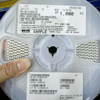
CL05A106MP5NUNC - 10µF 10V X5R 0402 MLCC | Samsung Electro-Mechanics
MPN: CL05A106MP5NUNC ✗ 停產CL05A106MP5NUNC 概覽
An MLCC (Multilayer Layer Ceramic Capacitor) is a passive component constructed by alternating layers of ceramic dielectric and metal electrodes, then sintered into a monolithic block. X5R is a Class 2 dielectric defined by EIA-198, offering moderate volumetric efficiency with capacitance change typically within ±15% over its rated temperature range. In the broader taxonomy, MLCCs sit under ceramic capacitors, which fall under capacitors, which fall under passive components. MLCCs dominate decoupling, bypass, and energy-storage applications in modern electronics because of their low ESR, low ESL, small footprint, and ability to be placed directly under IC power pins.
Key features of the CL05A106MP5NUNC include 10 µF nominal capacitance, ±20% tolerance, 10 V rated voltage, X5R dielectric, and a 0402 footprint (1.0 × 0.5 mm). The device is supplied in tape-and-reel packaging suitable for high-speed automated assembly. Per the manufacturer datasheet, the cap exhibits typical ESR well below 100 mΩ at 1 kHz, making it highly effective for high-frequency decoupling. The X5R temperature profile trades wide temperature stability for higher capacitance density compared to C0G/NP0 parts.
Typical applications include bulk decoupling of IC power rails, smartphone PMIC output filtering, IoT module bypass, and battery management bypass networks. The compact 0402 footprint supports high-density PCB layouts where board real estate is at a premium, particularly under SoCs and microcontrollers. Design engineers commonly select this part as a 1-3 piece-per-rail bypass capacitor paired with smaller 0.1 µF values.
When designing with X5R MLCCs, engineers must apply DC bias derating: a 10 µF 0402 X5R part may lose 60-80% of its nominal capacitance at 5 V DC bias. Always verify effective capacitance under operating voltage, not just nominal 1 Vrms capacitance. For designs requiring tight tolerance or low-loss RF coupling, C0G/NP0 dielectrics should be considered instead.
This page synthesizes distributor pricing, drop-in alternatives, and DC-bias-aware design notes not consolidated in any single manufacturer datasheet, supporting faster sourcing decisions for compact decoupling applications.
直接替換替代品,適用於 CL05A106MP5NUNC — 相同封裝,腳位對腳位相容。需重新設計 PCB 的不同封裝零件不列入。
此系列的變體
與下列產品可直接替換的同系列型號: CL05A106MP5NUNC (相同外形與佔位) — 差異在於 Capacitance, Capacitance Tolerance, Capacitor Type, Mounting Type, Operating Temperature Range.
CL05A106MP5NUNL
✅ 直接替換📋 參考替代品(不在目錄中)
CL05A106MQ5NUNC
✅ 直接替換📋 參考替代品(不在目錄中)
GRM155R61A106ME11
✅ 直接替換📋 參考替代品(不在目錄中)
CC0402MRX5R6BB106
✅ 直接替換📋 參考替代品(不在目錄中)
C1005X5R1A106M050BC
✅ 直接替換📋 參考替代品(不在目錄中)
KGM05AR51A106MH
✅ 直接替換📋 參考替代品(不在目錄中)
CL05A106MP5NUNC 最大額定值與電氣特性
| Capacitance | 10 µF |
| Capacitance Tolerance | ±20% |
| Rated Voltage | 10 V |
| Dielectric Characteristic | X5R (EIA) |
| 工作溫度範圍 | -55 °C to +85 °C |
| 封裝 / 外殼 | 0402 (1005 metric) |
| Package Size (inches) | 0.039 × 0.020 in |
| Package Size (mm) | 1.0 × 0.5 mm |
| 安裝類型 | Surface Mount (SMT) |
| Termination Style | Solder plated Ni/Sn (standard) |
| Capacitor Type | Multilayer Ceramic Capacitor (MLCC) |
| Temperature Coefficient | ±15% (X5R) |
| DC Bias Characteristic | Subject to DC bias derating (see datasheet) |
| RoHS 狀態 | Compliant |
| Packaging | Tape & Reel |
CL05A106MP5NUNC 1.0 × 0.5 mm 腳位配置指南
CL05A106MP5NUNC(1.0 × 0.5 mm 封裝)的腳位配置。 腳位編號、功能與連接圖定義於製造商資料手冊中。請參閱該手冊以取得確切的封裝尺寸與焊接指引。

無詳細腳位定義資料: CL05A106MP5NUNC.
請參閱 資料表 以查看完整腳位配置。
典型應用
CL05A106MP5NUNC 適用於 6 應用s: Microcontroller Power Rail Decoupling, Smartphone PMIC Output Filtering, IoT Wireless Module Bypass Network, Battery Management IC (BMIC) Bypass, USB-PD Controller Decoupling, Sensor Module Local Regulation.
Microcontroller Power Rail Decoupling
Place 1-3 pieces of CL05A106MP5NUNC directly beneath the VDD pins of a 32-bit MCU (e.g., a Cortex-M4 running at 180 MHz) to provide bulk energy storage between the regulator and the load. The 10 µF capacitance combined with 0402's sub-100 mΩ ESR at 1 MHz handles instantaneous load steps during code execution and peripheral activation. Compared to a single 10 µF tantalum, the X5R MLCC delivers equivalent or better high-frequency decoupling in roughly 1/3 the board area, enabling tighter SoC power-pin placement.
推薦
Smartphone PMIC Output Filtering
Use CL05A106MP5NUNC as output filter capacitance on PMIC LDO or buck outputs in compact mobile designs where board area is at a premium. The 0402 footprint supports direct placement under PMIC land pads while delivering 10 µF bulk capacitance for transient response during Wi-Fi or 5G RF power amplifier ramp events. Engineers should verify effective capacitance under 3.8-4.5 V DC bias, since X5R derating may reduce usable capacitance by 50-70% from the 10 µF nominal rating.
推薦
IoT Wireless Module Bypass Network
Pair CL05A106MP5NUNC with 0.1 µF X7R 0402 caps in parallel to form a wide-bandwidth bypass network for Wi-Fi/BLE module power pins. The 10 µF bulk handles low-frequency transient loading during TX bursts while the 0.1 µF handles high-frequency switching noise above 10 MHz. This 1+1 decoupling topology is standard for modules integrating Nordic nRF52, ESP32, and similar 3.3 V SoCs where clean power directly impacts RF performance and link stability.
推薦
Battery Management IC (BMIC) Bypass
Use CL05A106MP5NUNC as bulk bypass capacitance on BMIC input and output rails, supporting up to 2 A continuous discharge spikes during battery authentication and fuel-gauge measurement events. The 10 V rating provides ample headroom for charging voltages up to 9 V when used with quick-charge adapter front-ends. Compared to polymer capacitors, the MLCC delivers faster transient response in a smaller footprint for compact wearable and earbud designs.
推薦
USB-PD Controller Decoupling
Place CL05A106MP5NUNC on VBUS and CC line protection circuits of USB-PD controllers handling up to 5 A load. The 10 V rating exceeds USB-PD 9 V fast-charge levels with margin for transients, while the 0402 footprint enables tight placement adjacent to Type-C connector pins. Effective capacitance may drop below 5 µF at 5 V bias per X5R characteristics, so use 2-3 capacitors in parallel if bulk energy storage is critical for hot-plug events.
推薦
Sensor Module Local Regulation
Apply CL05A106MP5NUNC on the output of local LDO regulators powering MEMS sensors (accelerometers, gyros, environmental sensors) on IoT sensor boards. The X5R 10 µF MLCC filters LDO switching noise and provides instantaneous current during sensor wake/sleep transitions, which can spike to 10-50 mA. The compact 0402 footprint fits easily under sensor BGA packages where board area constraints are severe.
推薦
推薦產品摘要
工程參考資料,適用於 CL05A106MP5NUNC — 比較、設計指引及合規資訊。
選型指南
與替代品比較
| 參數 | 本產品 | CL05A106MP5NUNL | CL05A106MQ5NUNC | GRM155R61A106ME11 | CC0402MRX5R6BB106 | C1005X5R1A106M050BC | KGM05AR51A106MH |
|---|---|---|---|---|---|---|---|
| Package | 0402 (1005 metric) | 0402 (1005 metric) - same | 0402 (1005 metric) - same | 0402 (1005 metric) - same | 0402 (1005 metric) - same | 0402 (1005 metric) - same | 0402 (1005 metric) - same |
| Brand | Samsung Electro-Mechanics | Samsung Electro-Mechanics | Samsung Electro-Mechanics | Murata Manufacturing | YAGEO | TDK | KYOCERA AVX |
| Capacitance | 10 µF | 10 µF | 10 µF | 10 µF | 10 µF | 10 µF | 10 µF |
| Rated Voltage | 10 V | 10 V | 6.3 V | 10 V | 10 V | 10 V | 10 V |
| Tolerance | ±20% | ±20% | ±20% | ±20% | ±20% | ±20% | ±20% |
| Dielectric | X5R | X5R | X5R | X5R | X5R | X5R | X5R |
| Operating Temperature | -55 °C to +85 °C | -55 °C to +85 °C | -55 °C to +85 °C | -55 °C to +85 °C | -55 °C to +85 °C | -55 °C to +85 °C | -55 °C to +85 °C |
| Mounting Type | Surface Mount | Surface Mount | Surface Mount | Surface Mount | Surface Mount | Surface Mount | Surface Mount |
主要差異化特點
- Authorized Samsung Electro-Mechanics OEM sourcing (對比GRM155R61A106ME11 (Murata))
- 10 V rating provides headroom margin (對比CL05A106MQ5NUNC (6.3 V version))
- Compact 0402 footprint enables dense layouts (對比GRM155R61A106ME11 (Murata))
設計說明
Estimated: A 10 µF 0402 X5R MLCC may deliver only 2-4 µF effective capacitance at 5 V DC bias due to dielectric derating. Always check the manufacturer's DC bias curve for your actual operating voltage, and consider using 2-3 capacitors in parallel if bulk energy storage is critical. Nominal capacitance (measured at 0 V bias or 1 Vrms AC) overstates real-world available capacitance.
Recommended: Place the MLCC as close as possible to the IC power pin, ideally within 1-2 mm of the pad. Use vias-in-pad or short traces to minimize parasitic inductance. For high-current transients, pair the 10 µF bulk cap with a smaller 0.1 µF X7R 0402 in parallel to cover both low-frequency bulk storage and high-frequency decoupling above 10 MHz.
Optional: For solder reflow, follow JEDEC J-STD-020 profile with peak temperature not exceeding 260 °C for lead-free assembly. The 0402 package has limited thermal mass, so excessive dwell time above 200 °C can cause silver migration or thermal shock. Always use SAC305 (Sn96.5/Ag3.0/Cu0.5) solder paste for reliable 0402 solder joints.
合規資訊
RoHS compliant per Samsung product page. Not AEC-Q200 qualified for automotive - choose automotive-grade MLCC for AEC-Q200 designs. Conflict-minerals compliance per Samsung Electro-Mechanics declarations.