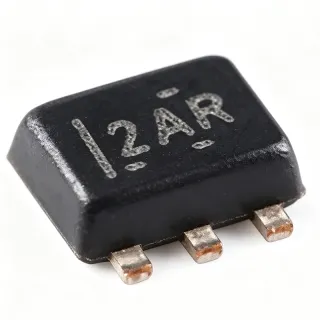
ESD1P0RFS-E6327 - 2-Channel 70V 10A TVS Array | Infineon
MPN: ESD1P0RFS-E6327 ✗ 停產ESD1P0RFS-E6327 概覽
A TVS diode array is a semiconductor protection component connected to sensitive signal lines. During an electrostatic discharge or transient event, the array diverts surge energy away from the protected circuit and clamps the signal voltage to a safer level. ESD1P0RFS belongs to the discrete-semiconductor protection hierarchy: TVS diode array, surge suppressor, ESD protection device, and discrete semiconductor.
The principal feature of ESD1P0RFS-E6327 is its low typical capacitance of 1 pF. Low capacitance helps preserve high-frequency signal behavior while still providing transient protection. Infineon’s application material identifies ESD1P0RFS as a low-capacitance anti-parallel configuration for one protected signal line with superimposed DC voltage, making it relevant to RF antennas, communications interfaces, and ultra-high-speed data lines. The verified search results also identify applications including GPS, HDMI, and Ethernet.
The array provides two-channel protection in a compact surface-mount package. Its verified protection claims include ±20 kV contact ESD and 10 A surge compliance, while the supplied comparison data lists IEC61000-4-2, IEC61000-4-4, and IEC61000-4-5 test categories. The 70 V standoff rating should not be interpreted as a general-purpose mains surge suppressor; engineers must verify that the protected signal, working voltage, and transient waveform remain within the device’s specified limits.
Typical RF placement is close to the connector or exposed interface, with the protected line routed through the array and the return path kept as short as practical. This minimizes parasitic inductance during fast ESD events and helps keep the clamp action close to the entry point. Placement decisions should be based on the manufacturer datasheet and the actual board stack-up rather than assumed equivalent pin functions.
A key design trade-off is capacitance versus protection capability: lower capacitance preserves signal integrity, but the device must still be checked against the required ESD and surge levels. The ESD1P0RFS-E6327 is best suited to applications where compact two-channel RF or high-speed-line protection is needed and the system’s operating voltages remain compatible with its 70 V reverse standoff rating.
This page combines verified manufacturer and distributor information, strict package-aware substitution screening, and practical placement guidance. It distinguishes confirmed ratings from unavailable specifications and avoids presenting unverified electrical limits as product facts.
直接替換替代品,適用於 ESD1P0RFS-E6327 — 相同封裝,腳位對腳位相容。需重新設計 PCB 的不同封裝零件不列入。
此系列的變體
與下列產品可直接替換的同系列型號: ESD1P0RFS-E6327 (相同外形與佔位) — 差異在於 Application Configuration, Channel Count, Device Type, Package, Surge Compliance.
ESD1P0RFW-E6327
✅ 直接替換聯絡詢價
查看資料表 →ESD1P0RFS
✅ 直接替換聯絡詢價
查看資料表 →ESD1P0RFSE6327HTSA1
✅ 直接替換📋 參考替代品(不在目錄中)
ESD1P0RFSH6327XTSA1
✅ 直接替換📋 參考替代品(不在目錄中)
ESD1P0RFWH6327XTSA1
✅ 直接替換📋 參考替代品(不在目錄中)
ESD1P0RFSE6327
✅ 直接替換📋 參考替代品(不在目錄中)
ESD1P0RFS-E6327 規格
| Product Type | Two-channel TVS diode array |
| Channel Count | 2 channels |
| Reverse Standoff Voltage | 70 V |
| Surge Current | 10 A |
| Typical Capacitance | 1 pF |
| Contact ESD Protection | ±20 kV |
| ESD Standard | IEC61000-4-2 |
| EFT Test Category | IEC61000-4-4, A (5/50 ns) |
| Surge Test Waveform | IEC61000-4-5, A (8/20 µs) |
| Application Configuration | Low-capacitance anti-parallel configuration |
| Protected Signal Lines | 1 protected signal line per cited application example |
| 封裝 | SOT-363 / 6-TSSOP / SC-88 |
| 安裝類型 | Surface mount |
| 腳位數 | 6 pins |
| Polarity | Unidirectional channel array |
ESD1P0RFS-E6327 sot-363 / 6-tssop / sc-88 腳位配置指南
ESD1P0RFS-E6327(sot-363 / 6-tssop / sc-88 封裝)的腳位配置。 腳位編號、功能與連接圖定義於製造商資料手冊中。請參閱該手冊以取得確切的封裝尺寸與焊接指引。
無詳細腳位定義資料: ESD1P0RFS-E6327.
請參閱 資料表 以查看完整腳位配置。
典型應用
ESD1P0RFS-E6327 適用於 6 應用s: RF Antenna Interface Protection, GPS and Navigation Interfaces, HDMI and High-Speed Digital Interfaces, Ethernet and Communications Equipment, Ultra-High-Speed Data-Line Protection, Industrial Control and Automation Interfaces.
RF Antenna Interface Protection
ESD1P0RFS-E6327 fits RF antenna connectors where electrostatic discharge can enter from an exposed cable or enclosure interface. Its verified 1 pF typical capacitance helps minimize loading of RF signals, while the cited ±20 kV contact ESD rating provides a defined protection target. The two-channel array can be positioned near the antenna-side connector so surge energy is diverted before reaching RF front-end circuitry. RF frequency, antenna bias voltage, return loss, and insertion loss should still be validated because the available data does not provide a complete RF frequency-response curve.
推薦
GPS and Navigation Interfaces
ESD1P0RFS-E6327 is suitable for protecting sensitive GPS or navigation-interface lines exposed to user contact, cable ESD, or nearby industrial transients. Infineon’s supplied application material explicitly identifies the ESD1P0RF family for GPS, and the target has two channels for coordinated protection of related lines. Its 1 pF typical capacitance is valuable where signal transitions and RF content must remain intact. Place the device close to the connector and verify antenna bias, cable length, ground strategy, and the exact IEC61000-4-2 test condition used by the manufacturer.
推薦
HDMI and High-Speed Digital Interfaces
ESD1P0RFS-E6327 can be considered for ESD protection at high-speed digital interfaces such as HDMI, where connector access and cable transients are common. The device’s verified 1 pF typical capacitance is a useful starting point for preserving edge rates, but the complete signal-integrity budget still depends on pad capacitance, routing, connector geometry, and receiver thresholds. The two-channel structure can protect adjacent interface conductors when the pin assignment is confirmed. Engineers should compare insertion loss and capacitance tolerance across the operating frequency range before release.
推薦
Ethernet and Communications Equipment
ESD1P0RFS-E6327 is relevant to communications equipment with exposed Ethernet, control, or antenna-related lines. Infineon identifies ESD1P0RF devices as suitable for communication interfaces, and the target’s low typical capacitance supports high-frequency signal routing better than a large general-purpose TVS diode. Protection placement at the chassis or connector entry point can reduce the voltage reaching a transceiver or controller. Verify the line’s normal voltage, isolation requirements, return-path design, and the manufacturer’s recommended layout, especially if the interface also uses Ethernet magnetics or long cables.
推薦
Ultra-High-Speed Data-Line Protection
ESD1P0RFS-E6327 is intended for ultra-high-speed data-line protection according to the supplied component description. The verified 1 pF typical capacitance is the central benefit because capacitance directly influences signal rise time, attenuation, and edge-rate-dependent behavior. In a practical board, the array should be close to the external connector so that an ESD event is intercepted before it propagates into the host controller. However, a complete design must verify differential impedance, return loss, connector parasitics, and the exact channel mapping; the available data does not include a frequency-dependent impedance plot.
推薦
Industrial Control and Automation Interfaces
ESD1P0RFS-E6327 can be evaluated for low-capacitance transient protection on industrial control, automation, and equipment I/O interfaces where operators or external wiring can introduce ESD. Its cited ±20 kV contact ESD capability and 10 A surge compliance provide useful starting criteria, while the compact SOT-363 package supports space-constrained boards. Industrial qualification requirements are not supplied, so automotive, medical, or extended-temperature claims should not be inferred. Validate the protected signal’s working voltage, isolation architecture, surge-energy budget, and the final placement against the manufacturer’s application guidance.
推薦
推薦產品摘要
工程參考資料,適用於 ESD1P0RFS-E6327 — 比較、設計指引及合規資訊。
選型指南
與替代品比較
| 參數 | 本產品 | ESD1P0RFW-E6327 | ESD1P0RFS | ESD1P0RFSE6327HTSA1 | ESD1P0RFWH6327XTSA1 |
|---|---|---|---|---|---|
| Package | SOT-363 / 6-TSSOP / SC-88 | SOT-363 | SOT-363 family | PG-SOT363-PO | PG-SOT323 |
| Brand | Infineon Technologies | Infineon Technologies | Infineon Technologies | Infineon Technologies | Infineon Technologies |
| Surge Current | 10 A | 10 A | 10 A | 10 A (8/20 µs) | 10 A (8/20 µs) |
| Mounting Type | Surface mount | Surface mount | Surface mount | Surface mount | Surface mount |
| Special Feature | Low-capacitance two-channel array | Low-capacitance one-channel RF ESD device | Low-capacitance two-channel RF ESD array | 15 V clamp ordering variant | One-channel RF ESD ordering variant |
主要差異化特點
- Two-channel protection in the documented SOT-363 family (對比ESD1P0RFW-E6327)
- Low typical capacitance for signal-preserving protection (對比ESD1P0RFW-E6327)
- Documented 70 V and 10 A protection ratings (對比ESD1P0RFWH6327XTSA1)
- RF-focused family positioning (對比ESD1P0RFS)
設計說明
Place the ESD1P0RFS-E6327 close to the connector or board entry point rather than deep inside the system. Keep the protected signal trace short and route the transient return path with low inductance. The device’s 1 pF typical capacitance is valuable for high-frequency lines, but placement still controls parasitic capacitance and ESD-current path. Confirm the six-pin orientation and channel mapping against the Infineon package drawing before committing the PCB footprint.
Do not treat the 70 V reverse standoff rating as proof that every protected line may operate at 70 V. Check the signal’s maximum DC voltage, AC excursions, antenna bias, and tolerance margin against the manufacturer’s working-voltage data. Likewise, do not use the 10 A surge value as a continuous-current rating. The supplied data identifies ±20 kV contact ESD and transient test categories, but the complete clamp, pulse-energy, and operating-voltage details are [DATA_NEEDED: full electrical characteristics].
Use the manufacturer’s recommended anti-parallel or channel connection exactly as shown in the application example. Because the ESD1P0RFS family is intended for RF and high-speed lines, avoid long exposed traces between the connector, protection device, and protected circuit. Keep the device’s ground or return connection short and inspect the assembled board for solder bridges around the six-pin SOT-363 footprint. Signal-integrity validation should include rise-time and eye-width measurements when the line is a high-speed digital interface.
ESD1P0RFS-E6327 is a protection device, not a regulator or power converter. Do not calculate continuous power dissipation from the 10 A surge figure; transient current is limited by the source impedance, waveform, and duration. If the protected interface also sees sustained overvoltage or surge energy beyond the verified ESD ratings, coordinate the TVS with upstream current limiting and downstream surge protection. The supplied data does not provide continuous power dissipation or complete SOA data.
合規資訊
The supplied verified data identifies IEC61000-4-2, IEC61000-4-4, and IEC61000-4-5 transient-protection test categories, but it does not explicitly state RoHS, REACH, AEC-Q100, lead-free, halogen-free, or conflict-minerals status for this exact ordering code.