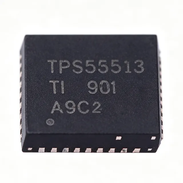
TPS53513RVER - 8A, 18V Sync Buck Converter | Texas Instruments
MPN: TPS53513RVER ✓ 啟用中| 數量 | 單價 | 小計 |
|---|---|---|
| 1 | $5.18 | $5.18 |
| 10 | $4.92 | $49.20 |
| 100 | $4.41 | $441.00 |
| 500 | $3.95 | $1,975.00 |
| 1,000 | $3.55 | $3,550.00 |
TPS53513RVER 概覽
A synchronous buck converter is a type of DC-DC switching regulator that steps a higher input voltage down to a lower output voltage using two integrated MOSFETs (a high-side and a low-side switch) instead of an external Schottky diode. Within the power management IC hierarchy, it belongs to the family of switching voltage regulators, which achieve far higher efficiency than linear regulators, making them the standard choice for point-of-load power conversion in digital systems.
Key features of the TPS53513 include integrated 13.8-mOhm high-side and 5.9-mOhm low-side MOSFETs delivering 8 A of continuous output current, a precision 600 mV reference with 0.5% tolerance, support for all-ceramic output capacitors, and an integrated boost switch that eliminates one more external component.
Technically, the D-CAP3 control topology is an adaptive on-time architecture that provides fast transient response to load steps without complex loop compensation, allowing a very low external-component count. Because switching frequency adapts to input and output conditions, the converter maintains good efficiency across light and heavy loads while supporting high step-down ratios from 18 V rails.
Typical applications include powering FPGAs, ASICs, microprocessors, and DSP cores in networking, telecom, industrial, and server equipment, where a compact 8 A point-of-load solution from a 12 V intermediate bus is required.
For design, note the device is specified from -40C to +85C ambient; at 8 A loads with 18 V input, thermal design of the exposed-pad PCB land pattern is critical, and all-ceramic output capacitance must be verified against D-CAP3 stability requirements.
This page synthesizes distributor pricing, drop-in alternatives, comparison tables, and practical design notes not found in the manufacturer datasheet alone.
直接替換替代品,適用於 TPS53513RVER — 相同封裝,腳位對腳位相容。需重新設計 PCB 的不同封裝零件不列入。
此系列的變體
與下列產品可直接替換的同系列型號: TPS53513RVER (相同外形與佔位) — 差異在於 Control Mode, Package, Topology, Input Voltage Range, Output Voltage Range.
快速比較工具 — 選擇替代零件進行並排比較:
TPS53515RVER
✗ 缺貨
$2.32 / 單位
查看資料表 →TPS53513RVET
📋 參考替代品(不在目錄中)
TPS53513RVER 最大額定值與電氣特性
| 拓撲 | Synchronous step-down (buck) converter |
| Control Mode | D-CAP3 adaptive on-time |
| 輸入電壓範圍 | 1.5 V to 18 V |
| 輸出電壓範圍 | 0.6 V to 5.5 V (adjustable) |
| 最大輸出電流 | 8 A continuous |
| 參考電壓 | 600 mV +/-0.5% |
| High-Side MOSFET Rds(on) | 13.8 mOhm (integrated) |
| Low-Side MOSFET Rds(on) | 5.9 mOhm (integrated) |
| 輸出數量 | 1 |
| Output Capacitor Type | All-ceramic supported |
| Integrated Boost Switch | Yes |
| Operating Ambient Temperature | -40C to +85C |
| 封裝 | 28-VFQFN Exposed Pad (RVE), VQFN-28 |
| 安裝類型 | Surface Mount |
| Packing | Tape & Reel (R suffix) |
| RoHS 狀態 | RoHS-Exempt & Green (per TI E2E forum) |
| Unit Price (reference) | $5.1761 (as of 2026-09-10, Heisener) |
TPS53513RVER 28-vfqfn exposed pad (rve), vqfn-28 腳位配置指南
TPS53513RVER(28-vfqfn exposed pad (rve), vqfn-28 封裝)的腳位配置。 此功率元件具有閘極、汲極與源極端子。對於非極性封裝,請參閱製造商資料表以取得確切的第 1 腳方向與佈局詳細資訊。常見應用包括電源設計、馬達驅動與負載切換。

無詳細腳位定義資料: TPS53513RVER.
請參閱 資料表 以查看完整腳位配置。
安全工作區
典型應用
TPS53513RVER 適用於 6 應用s: FPGA and ASIC Core Power, Networking and Telecom Equipment, Industrial Automation and Control, Server and Data Center Point-of-Load, DSP and Microprocessor Power, Compact Point-of-Load Modules.
FPGA and ASIC Core Power
The TPS53513RVER is well suited to powering FPGA and ASIC core rails because these loads combine high transient current steps with tight voltage windows. Its 8 A continuous rating covers mid-range FPGA core supplies, while the D-CAP3 adaptive on-time control responds to load steps within microseconds, minimizing droop on rails such as 1.0 V or 1.2 V derived from a 12 V intermediate bus. The 600 mV +/-0.5% reference supports low core voltages with margin to spare, and all-ceramic output capacitance keeps the solution height low for dense boards. Placed near the load with a compact inductor and ceramic output bank, the integrated 13.8-mOhm/5.9-mOhm MOSFET power stage delivers high efficiency without external FETs, though designers should budget board copper for thermal dissipation near full 8 A loads.
推薦
Networking and Telecom Equipment
Networking switches, routers, and telecom line cards typically distribute a 12 V intermediate bus and need multiple compact point-of-load converters for MAC, PHY, and memory supplies. The TPS53513RVER fits this pattern directly: its 1.5 V to 18 V input accepts the 12 V bus with margin, and its 8 A capability covers high-draw digital loads such as switch ASICs and network processors. The very low external-component count of the D-CAP3 architecture shortens design time and reduces board area on dense line cards, while all-ceramic output capacitors improve long-term reliability expected in always-on telecom infrastructure. The -40C to +85C ambient specification covers telecom equipment environmental requirements, and the 28-VFQFN exposed pad package supports thermally enhanced layouts on standard multilayer PCBs.
推薦
Industrial Automation and Control
Industrial control systems, PLCs, and motor-drive controllers demand robust, efficient point-of-load conversion from 12 V or 24 V-adjacent buses. The TPS53513RVER operates from 1.5 V to 18 V input, making it ideal for 12 V industrial rails, and its 8 A output powers embedded processors, DSPs, and I/O logic in one compact stage. The D-CAP3 control mode tolerates ceramic-only output networks, which resist vibration and dry-out failure modes that affect electrolytic capacitors in industrial environments. Its -40C to +85C ambient range matches unconditioned factory-floor enclosures. Because integrated MOSFETs remove external power-stage tuning, one proven design can be reused across product variants, reducing qualification effort. Careful exposed-pad soldering and copper pour are recommended to handle worst-case load and hot-ambient combinations.
推薦
Server and Data Center Point-of-Load
Server motherboards and storage systems use distributed 12 V power architectures that feed many point-of-load converters for CPU auxiliaries, memory, ASICs, and SSD controllers. The TPS53513RVER serves mid-current rails up to 8 A with high efficiency from its integrated 13.8-mOhm and 5.9-mOhm MOSFETs, directly reducing converter losses and heat in thermally constrained chassis. The adaptive on-time D-CAP3 control handles the sharp load transients typical of bursty data-center workloads, and the 0.5%-accurate 600 mV reference enables low-voltage rails with tight regulation windows. All-ceramic output capacitance extends service life compared with electrolytic solutions, supporting the multi-year duty cycles expected of server hardware, while the small 28-VFQFN footprint preserves board space around dense processor power trees.
推薦
DSP and Microprocessor Power
Digital signal processors and embedded microprocessors require stable low-voltage rails with good transient behavior during compute bursts. The TPS53513RVER delivers adjustable outputs from 0.6 V to 5.5 V, covering common 1.0 V, 1.2 V, 1.35 V, and 1.8 V DSP and MCU core and I/O supplies from a single 12 V or 5 V input. Its 8 A capacity suits higher-performance DSPs, while the fast D-CAP3 load-step response prevents core-voltage excursions during sudden processing loads that could trigger brownouts or clock throttling. The integrated boost switch simplifies the bootstrap design, reducing external-component count to an inductor, a few resistors, and ceramic capacitors. For lower-current DSP variants in the same family footprint, the 5 A TPS53515RVER offers a pin-compatible cost-optimized option.
推薦
Compact Point-of-Load Modules
Power-module makers and board designers building small POL bricks benefit from the TPS53513RVER's very low external-component count: integrated MOSFETs, integrated boost switch, D-CAP3 control without external compensation, and all-ceramic output support mean the entire converter needs only an input filter, inductor, and small ceramic bank. The 28-VFQFN exposed pad package keeps the power stage compact, enabling high power density on standard PCBs. The wide 1.5 V to 18 V input range lets one module design serve 5 V, 12 V, and bus-derived inputs, simplifying product lines. The 8 A rating with a 0.5% 600 mV reference covers most digital rails. Thermal spreading through the exposed pad must be engineered into the module substrate, especially for continuous full-load operation in enclosed housings.
推薦
推薦產品摘要
工程參考資料,適用於 TPS53513RVER — 比較、設計指引及合規資訊。
選型指南
與替代品比較
| 參數 | 本產品 | TPS53515RVER | TPS53513RVET |
|---|---|---|---|
| Package | 28-VFQFN Exposed Pad (RVE) | 28-VFQFN Exposed Pad (RVE) - same | 28-VFQFN Exposed Pad (RVE) - same |
| Brand | Texas Instruments | Texas Instruments | Texas Instruments |
| Maximum Output Current | 8 A | 5 A | 8 A |
| Input Voltage Range | 1.5 V to 18 V | 1.5 V to 18 V | 1.5 V to 18 V |
| Output Voltage Range | 0.6 V to 5.5 V | 0.6 V to 5.5 V | 0.6 V to 5.5 V |
| Control Mode | D-CAP3 adaptive on-time | D-CAP3 adaptive on-time | D-CAP3 adaptive on-time |
| Reference Voltage Tolerance | 600 mV +/-0.5% | 600 mV +/-0.5% | 600 mV +/-0.5% |
| RoHS / Green Status | RoHS-Exempt & Green | RoHS-Exempt & Green (per TI E2E) | RoHS-Exempt & Green (per TI E2E) |
主要差異化特點
- 8 A continuous current with fully integrated power stage (對比TPS53515RVER)
- D-CAP3 control with all-ceramic output support (對比TPS53626RSMR)
- Trade-off: fixed single-rail 8 A solution (對比TPS53515RVER)
設計說明
The 28-VFQFN exposed pad is the primary thermal path for the TPS53513RVER; solder it to a solid ground plane with an array of thermal vias (typically 5x5 or larger under the pad). Estimated: at 8 A load and 12 V to 1.2 V conversion, high-side conduction loss alone is roughly I2 x Rds(on) x duty = 64 x 0.0138 x 0.1, about 0.09 W, but switching losses at high VIN and high frequency add significantly - verify junction temperature with the datasheet thermal metrics and your switching frequency. Keep hot ambient derating in mind: the device is specified to +85C ambient.
Place the input ceramic capacitors, inductor, and output capacitors as close to the IC as possible. Keep the SW node (inductor connection) copper area small to reduce radiated EMI, and route the feedback trace away from the switch node and inductor to avoid noise coupling into the 600 mV reference node. Use a solid ground plane under the converter and connect the exposed pad directly to it with multiple vias. Follow the PCB layout guidelines in the TI TPS53513 datasheet, which provides a proven two-layer and four-layer layout example.
Although the TPS53513 supports all-ceramic output capacitors, verify total output capacitance against the D-CAP3 stability and transient requirements in the datasheet - excessive ceramic capacitance can affect adaptive on-time behavior during startup. Do not exceed the 18 V absolute maximum on VIN; add margin or a TVS on supply rails with transients. Set the output voltage with 1%-tolerance resistors to preserve the 0.5% reference accuracy. Note the R and T orderable suffixes are the same silicon (TI E2E confirmation) - buy whichever reel quantity is available.
合規資訊
Per TI E2E forum response, TPS53513RVER and TPS53513RVET are RoHS-Exempt & Green. Green indicates halogen-free packaging. REACH, lead-free, and conflict-minerals status should be confirmed on the TI.com quality/environmental pages.






