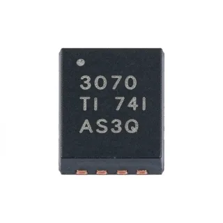
TUSB213RGYR - USB 2.0 HS Redriver with DC Boost | Texas Instruments
MPN: TUSB213RGYR ✓ 啟用中TUSB213RGYR 概覽
A USB redriver is a signal-processing interface integrated circuit placed between a USB transmitter and receiver. It detects degradation on a high-speed differential pair and applies selectable equalization to restore eye opening. Unlike a repeater or hub controller, the TUSB213 does not interpret USB packets or maintain device firmware; its primary role is analog signal recovery between the USB PHY and connector.
The TUSB213 provides pin-strap or I2C configuration for low-speed, full-speed, and high-speed signaling. Four selectable AC boost settings allow the equalization to be tuned for different interconnect losses. Its disconnect and shutdown functions can reduce power consumption when a port is inactive. The device also supports daisy chaining to address high-loss channels, and interchangeable D1P/M and D2P/M routing helps simplify board planning.
According to the Texas Instruments TUSB213 product page, the redriver is compatible with USB 2.0, OTG 2.0, and BC 1.2. It can support up to 5 meters of pre-channel cable length or 2 meters of post-channel cable length. These figures describe intended channel reach rather than a guarantee for every cable, connector, PCB, or environmental condition.
Typical uses include USB Type-C and legacy USB-A ports, external storage, docking stations, cameras, test equipment, and industrial control panels. The DC-boost function can add a controlled DC component to a differential data signal, while selectable AC boost compensates high-frequency attenuation. Correct implementation requires preserving controlled-impedance routing between the source PHY, redriver, connector, and receiving PHY.
Design the power rails so they remain within the 4.4 V to 5.5 V operating range, and place the redriver close to the connector when loss occurs mainly in cable or connector transitions. Configure boost through pins or I2C, evaluate eye closure with the intended channel, and verify low-speed and full-speed bypass behavior after high-speed equalization is enabled.
This page combines the manufacturer feature set, packaging information, ordering variants, drop-in alternatives, application guidance, and design considerations into one engineering-focused reference. It also provides a parameter comparison to help assess whether a same-package variant is appropriate for a specific USB channel.
直接替換替代品,適用於 TUSB213RGYR — 相同封裝,腳位對腳位相容。需重新設計 PCB 的不同封裝零件不列入。
此系列的變體
與下列產品可直接替換的同系列型號: TUSB213RGYR (相同外形與佔位) — 差異在於 Package.
TUSB213IRGYT
✅ 直接替換📋 參考替代品(不在目錄中)
TUSB213QRGYRQ1
✅ 直接替換📋 參考替代品(不在目錄中)
TUSB215RGYT
✅ 直接替換聯絡詢價
查看資料表 →TUSB215QRGYTQ1
✅ 直接替換📋 參考替代品(不在目錄中)
TUSB213RGYT
✅ 直接替換 ⚠️ 規格未經驗證聯絡詢價
查看資料表 →TUSB213RGYR 規格
| Product Type | USB 2.0 high-speed redriver with DC boost |
| USB Compatibility | USB 2.0, OTG 2.0, and BC 1.2 |
| Maximum USB Data Rate | 480 Mbit/s |
| High-Speed Channel Count | 1 channel |
| Supported Signaling Modes | Low-speed, full-speed, and high-speed |
| Supply Voltage Range | 4.4 V to 5.5 V |
| AC Boost Settings | 4 selectable settings |
| Configuration Interface | Pin strap or I2C |
| Maximum Pre-Channel Cable Length | 5 m |
| Maximum Post-Channel Cable Length | 2 m |
| Data Pair Routing | Interchangeable D1P/M and D2P/M |
| Host and Device Operation | Host-agnostic and device-agnostic |
| Daisy-Chain Support | Yes |
| Low-Speed and Full-Speed Behavior | Automatically bypassed |
| Power Management Features | Ultra-low USB disconnect and shutdown |
| 封裝 | 14-pin VQFN (RGY), 3.5 mm x 3.5 mm |
| 安裝類型 | Surface mount |
| RoHS 狀態 | RoHS3 compliant |
TUSB213RGYR 14-pin vqfn (rgy), 3.5 mm x 3.5 mm 腳位配置指南
TUSB213RGYR(14-pin vqfn (rgy), 3.5 mm x 3.5 mm 封裝)的腳位配置。 腳位編號、功能與連接圖定義於製造商資料手冊中。請參閱該手冊以取得確切的封裝尺寸與焊接指引。

無詳細腳位定義資料: TUSB213RGYR.
請參閱 資料表 以查看完整腳位配置。
典型應用
TUSB213RGYR 適用於 6 應用s: USB Type-C Port Signal Conditioning, USB Docking Station, External Storage and Peripherals, Industrial Control and Measurement, USB Test and Compliance Equipment, Camera and Imaging Peripherals.
USB Type-C Port Signal Conditioning
The TUSB213RGYR is useful between a USB 2.0 controller and a Type-C connector when trace, connector, and cable losses reduce high-speed eye margin. Its 480 Mbit/s USB 2.0 channel, four selectable AC boost settings, and automatic low-speed and full-speed bypass allow the equalization to be tuned without changing the logical USB behavior. The 3.5 mm by 3.5 mm VQFN also preserves board area beside compact Type-C receptacles. The designer should retain controlled-impedance routing, minimize stubs, and evaluate the setting with the intended cable and connector because nominal cable length alone does not define total channel loss.
推薦
USB Docking Station
A docking station can place the TUSB213RGYR near an external USB connector to recover high-speed signal degradation caused by long internal traces and connector transitions. The redriver preserves USB 2.0 operation at up to 480 Mbit/s and automatically bypasses lower-speed devices while high-speed equalization is active. Four AC boost settings allow adjustment across different shell, cable, and PCB combinations. The principal trade-off is added component placement and configuration: the equalizer must be positioned at the correct channel boundary, and its settings should be validated through eye measurements rather than inferred solely from connector type.
推薦
External Storage and Peripherals
The TUSB213RGYR can improve an external storage or peripheral connection when USB high-speed pair degradation appears across an internal harness, connector, or PCB transition. Its DC boost and selectable AC boost settings provide two complementary mechanisms for restoring signal integrity, while automatic bypass allows low-speed and full-speed devices to continue operating normally. Because the TUSB213 is a redriver rather than a storage controller, it does not affect command translation, USB enumeration, or data-protocol behavior. Validation should include the slowest and fastest supported devices because automatic bypass and high-speed compensation must coexist correctly.
推薦
Industrial Control and Measurement
Industrial controllers and measurement equipment can use the TUSB213RGYR to protect USB 2.0 high-speed links that cross long PCB routes or connect through ruggedized receptacles. The 4.4 V to 5.5 V operating range supports conventional 5 V USB power architecture, and the compact 14-pin VQFN simplifies placement near the interface connector. Four AC boost levels allow adaptation to multiple cable and enclosure arrangements. The redriver does not provide the functional safety of the surrounding control system, so designers should isolate its role as a signal-conditioning element and verify operation across temperature, power, and cable conditions used in the target equipment.
推薦
USB Test and Compliance Equipment
In USB test fixtures and compliance equipment, the TUSB213RGYR can introduce controlled high-speed channel compensation into a deliberately impaired link. Its selectable AC boost settings make it possible to compare receiver behavior across different effective channel-loss conditions, while DC boost supports the redriver’s transmission architecture. The device’s transparency to low-speed and full-speed traffic permits mixed-speed test scenarios. Engineers should document each boost setting and physical channel configuration so measurements remain repeatable, and should treat the 5 m pre-channel and 2 m post-channel figures as design targets rather than universal guarantees.
推薦
Camera and Imaging Peripherals
The TUSB213RGYR can support camera or imaging peripheral links where a USB 2.0 high-speed channel crosses a connector, cable, or compact internal harness that causes attenuation. Its 480 Mbit/s redriver capability targets USB 2.0 data integrity rather than image processing, and the automatic bypass of low-speed and full-speed traffic allows one design to support multiple device speeds. The compact 14-pin VQFN helps place compensation near the connector where channel loss often increases. System testing should include the camera vendor’s specified cable, host controller, operating system, and power state because enumeration timing and driver behavior are outside the redriver’s control.
推薦
推薦產品摘要
工程參考資料,適用於 TUSB213RGYR — 比較、設計指引及合規資訊。
選型指南
與替代品比較
| 參數 | 本產品 | TUSB213IRGYT | TUSB213QRGYRQ1 | TUSB215RGYT | TUSB215QRGYTQ1 |
|---|---|---|---|---|---|
| Package | 14-VQFN (RGY), 3.5 mm x 3.5 mm | 14-VQFN (RGY) | 14-VQFN (RGY) | 14-VQFN (RGY) | 14-VQFN (RGY) |
| Brand | Texas Instruments | Texas Instruments | Texas Instruments | Texas Instruments | Texas Instruments |
| Device Type | USB 2.0 high-speed signal conditioner with DC boost | TUSB213-family USB signal conditioner | USB 2.0 high-speed signal conditioner | USB 2.0 high-speed signal conditioner with integrated CDP and VBUS supply | USB 2.0 high-speed signal conditioner |
| Maximum USB Data Rate | 480 Mbit/s | 480 Mbit/s | 480 Mbit/s | 480 Mbit/s | 480 Mbit/s |
主要差異化特點
- Provides DC boost in addition to four selectable AC boost levels (對比TUSB215RGYT)
- Supports USB 2.0, OTG 2.0, and BC 1.2 interfaces (對比TUSB213QRGYRQ1)
- Provides an automotive-orderable family alternative (對比TUSB213IRGYT)
設計說明
Treat the redriver as a compensation boundary, not as a universal cable-length fix. Measure eye width, differential impedance, and mode conversion with the final PCB, connector, and cable combination, then select one of the four AC boost settings accordingly. Keep the USB high-speed pair as a short, continuous 100-ohm differential path and remove test pads or unused branches that create impedance discontinuities.
Position the TUSB213RGYR close to the loss-producing interface when attenuation is dominated by the connector or cable. Follow the manufacturer layout pattern for input and output routing, supply decoupling, exposed-pad connection, and ground-via placement. Avoid routing the differential pair through multiple layers, and maintain symmetry between P and M conductors to limit mode conversion and maintain consistent edge rates.
Operate the device only within its 4.4 V to 5.5 V supply range. Place local high-frequency decoupling at the supply and ground pins using the values and layout specified by the manufacturer datasheet. Verify startup, shutdown, and reconnect behavior because an invalid rail excursion or excessive supply transient can create failures that appear elsewhere in the USB enumeration or signal-integrity test results.
Do not assume that identical 14-VQFN packages guarantee interchangeable behavior. Before replacing the TUSB213RGYR with TUSB213QRGYRQ1, TUSB215RGYT, or another RGY variant, compare pin assignments, supply limits, exposed-pad requirements, configuration registers, boost behavior, and auxiliary functions. Pay particular attention to the integrated CDP and VBUS supply identified for TUSB215RGYT, which may change the surrounding application circuit.
合規資訊
The product listing identifies the TUSB213RGYR as RoHS3 compliant. Other compliance and material-declaration statuses are not stated in the product information.