
Texas Instruments

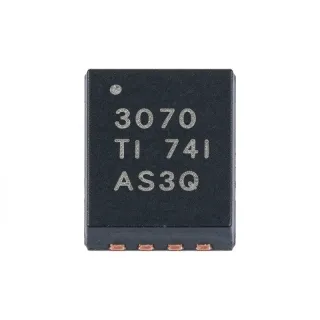
TUSB213RGYR - USB 2.0 HS Redriver with DC Boost | Texas Instruments

부품 번호: TUSB213RGYR ✓ 활성
4.4 V to 5.5 V Vdss 14-pin VQFN (RGY), 3.5 mm x 3.5 mm Package 1 channel Speed
MOQ: 1 |

TUSB213RGYR 개요

Texas Instruments TUSB213RGYR is a USB 2.0 high-speed signal conditioner with DC boost, optimized for restoring degraded USB data pairs across lossy interconnect. The device supports USB 2.0 high-speed, USB 2.0 OTG 2.0, and Battery Charging 1.2 operation, with one configurable high-speed data channel. Its 4.4 V to 5.5 V supply range and 14-pin VQFN package in a compact 3.5 mm by 3.5 mm footprint suit space-constrained USB ports, cable assemblies, docking systems, and embedded host or device designs.

A USB redriver is a signal-processing interface integrated circuit placed between a USB transmitter and receiver. It detects degradation on a high-speed differential pair and applies selectable equalization to restore eye opening. Unlike a repeater or hub controller, the TUSB213 does not interpret USB packets or maintain device firmware; its primary role is analog signal recovery between the USB PHY and connector.

The TUSB213 provides pin-strap or I2C configuration for low-speed, full-speed, and high-speed signaling. Four selectable AC boost settings allow the equalization to be tuned for different interconnect losses. Its disconnect and shutdown functions can reduce power consumption when a port is inactive. The device also supports daisy chaining to address high-loss channels, and interchangeable D1P/M and D2P/M routing helps simplify board planning.

According to the Texas Instruments TUSB213 product page, the redriver is compatible with USB 2.0, OTG 2.0, and BC 1.2. It can support up to 5 meters of pre-channel cable length or 2 meters of post-channel cable length. These figures describe intended channel reach rather than a guarantee for every cable, connector, PCB, or environmental condition.

Typical uses include USB Type-C and legacy USB-A ports, external storage, docking stations, cameras, test equipment, and industrial control panels. The DC-boost function can add a controlled DC component to a differential data signal, while selectable AC boost compensates high-frequency attenuation. Correct implementation requires preserving controlled-impedance routing between the source PHY, redriver, connector, and receiving PHY.

Design the power rails so they remain within the 4.4 V to 5.5 V operating range, and place the redriver close to the connector when loss occurs mainly in cable or connector transitions. Configure boost through pins or I2C, evaluate eye closure with the intended channel, and verify low-speed and full-speed bypass behavior after high-speed equalization is enabled.

This page combines the manufacturer feature set, packaging information, ordering variants, drop-in alternatives, application guidance, and design considerations into one engineering-focused reference. It also provides a parameter comparison to help assess whether a same-package variant is appropriate for a specific USB channel.

드롭인 대체품: TUSB213RGYR — 동일 패키지, 핀 호환. PCB 재작업이 필요한 다른 패키지 부품은 제외됩니다.

이 시리즈의 변형

다음과 드롭인 호환되는 동일 시리즈 모델: TUSB213RGYR (동일 폼 팩터 및 풋프린트) — 차이점: Package.

Texas Instruments
Package: 14-pin VQFN (RGY), 3.5 x 3.5 mm
비교 대상: TUSB213RGYR →

TUSB213IRGYT

✅ 드롭인
📦 14-VQFN (RGY)
Same TUSB213 family and 14-VQFN RGY class; comparison information identifies differences in supply-voltage range and power consumption, with no exact percentage stated.

📋 참조 대체품 (카탈로그에 없음)

TUSB213QRGYRQ1

✅ 드롭인
📦 14-VQFN (RGY)
Same TUSB213 family and 14-VQFN RGY footprint; Q1 orderable variant adds automotive qualification while retaining the 480 Mbit/s USB 2.0 redriver function.

📋 참조 대체품 (카탈로그에 없음)

TUSB215RGYT

✅ 드롭인
Texas Instruments
📦 14-VQFN (RGY)
USB 2.0 high-speed signal conditioner · 480 Mbit/s high speed · USB 2.0, OTG 2.0, BC 1.2 · Low-Speed, Full-Speed, High-Speed · 1 · Supported · Integrated USB BC1.2 CDP · Pin strap or I²C

가격 문의

데이터시트 보기 →

TUSB215QRGYTQ1

✅ 드롭인
📦 14-VQFN (RGY)
Same 480 Mbit/s USB 2.0 redriver class and 14-VQFN RGY package; Q1 orderable variant adds automotive qualification and uses a different tape-and-reel suffix.

📋 참조 대체품 (카탈로그에 없음)

TUSB213RGYT

✅ 드롭인 ⚠️ 사양 미검증
Texas Instruments
📦 14-VQFN (RGY)
USB 2.0 high-speed signal conditioner with DC boost · USB 2.0, OTG 2.0, and Battery Charging 1.2 · Low speed, full speed, and high speed · 4.4 V to 5.5 V · Pin strap or I2C · 4 selectable settings · Supported · 5 m

가격 문의

데이터시트 보기 →

TUSB213RGYR 사양

Product Type USB 2.0 high-speed redriver with DC boost
USB Compatibility USB 2.0, OTG 2.0, and BC 1.2
Maximum USB Data Rate 480 Mbit/s
High-Speed Channel Count 1 channel
Supported Signaling Modes Low-speed, full-speed, and high-speed
Supply Voltage Range 4.4 V to 5.5 V
AC Boost Settings 4 selectable settings
Configuration Interface Pin strap or I2C
Maximum Pre-Channel Cable Length 5 m
Maximum Post-Channel Cable Length 2 m
Data Pair Routing Interchangeable D1P/M and D2P/M
Host and Device Operation Host-agnostic and device-agnostic
Daisy-Chain Support Yes
Low-Speed and Full-Speed Behavior Automatically bypassed
Power Management Features Ultra-low USB disconnect and shutdown
패키지 14-pin VQFN (RGY), 3.5 mm x 3.5 mm
실장 유형 Surface mount
RoHS 상태 RoHS3 compliant

TUSB213RGYR 14-pin vqfn (rgy), 3.5 mm x 3.5 mm 핀 구성 가이드

TUSB213RGYR(14-pin vqfn (rgy), 3.5 mm x 3.5 mm 패키지)의 핀 구성입니다. 핀 번호, 기능, 연결 다이어그램은 제조사 데이터시트에 정의되어 있습니다. 정확한 풋프린트와 솔더링 지침은 해당 문서를 참조하십시오.

TUSB213RGYR의 14-pin vqfn (rgy), 3.5 mm x 3.5 mm 패키지 핀아웃 다이어그램

다음에 대한 상세 핀아웃 데이터 없음: TUSB213RGYR.

다음을 참조하십시오: 데이터시트 전체 핀 구성은 다음을 참조하십시오.

일반적인 애플리케이션

TUSB213RGYR 적합 용도: 6 애플리케이션s: USB Type-C Port Signal Conditioning, USB Docking Station, External Storage and Peripherals, Industrial Control and Measurement, USB Test and Compliance Equipment, Camera and Imaging Peripherals.

📱

USB Type-C Port Signal Conditioning

The TUSB213RGYR is useful between a USB 2.0 controller and a Type-C connector when trace, connector, and cable losses reduce high-speed eye margin. Its 480 Mbit/s USB 2.0 channel, four selectable AC boost settings, and automatic low-speed and full-speed bypass allow the equalization to be tuned without changing the logical USB behavior. The 3.5 mm by 3.5 mm VQFN also preserves board area beside compact Type-C receptacles. The designer should retain controlled-impedance routing, minimize stubs, and evaluate the setting with the intended cable and connector because nominal cable length alone does not define total channel loss.

🖥️

USB Docking Station

A docking station can place the TUSB213RGYR near an external USB connector to recover high-speed signal degradation caused by long internal traces and connector transitions. The redriver preserves USB 2.0 operation at up to 480 Mbit/s and automatically bypasses lower-speed devices while high-speed equalization is active. Four AC boost settings allow adjustment across different shell, cable, and PCB combinations. The principal trade-off is added component placement and configuration: the equalizer must be positioned at the correct channel boundary, and its settings should be validated through eye measurements rather than inferred solely from connector type.

🖥️

External Storage and Peripherals

The TUSB213RGYR can improve an external storage or peripheral connection when USB high-speed pair degradation appears across an internal harness, connector, or PCB transition. Its DC boost and selectable AC boost settings provide two complementary mechanisms for restoring signal integrity, while automatic bypass allows low-speed and full-speed devices to continue operating normally. Because the TUSB213 is a redriver rather than a storage controller, it does not affect command translation, USB enumeration, or data-protocol behavior. Validation should include the slowest and fastest supported devices because automatic bypass and high-speed compensation must coexist correctly.

🏭

Industrial Control and Measurement

Industrial controllers and measurement equipment can use the TUSB213RGYR to protect USB 2.0 high-speed links that cross long PCB routes or connect through ruggedized receptacles. The 4.4 V to 5.5 V operating range supports conventional 5 V USB power architecture, and the compact 14-pin VQFN simplifies placement near the interface connector. Four AC boost levels allow adaptation to multiple cable and enclosure arrangements. The redriver does not provide the functional safety of the surrounding control system, so designers should isolate its role as a signal-conditioning element and verify operation across temperature, power, and cable conditions used in the target equipment.

🧩

USB Test and Compliance Equipment

In USB test fixtures and compliance equipment, the TUSB213RGYR can introduce controlled high-speed channel compensation into a deliberately impaired link. Its selectable AC boost settings make it possible to compare receiver behavior across different effective channel-loss conditions, while DC boost supports the redriver’s transmission architecture. The device’s transparency to low-speed and full-speed traffic permits mixed-speed test scenarios. Engineers should document each boost setting and physical channel configuration so measurements remain repeatable, and should treat the 5 m pre-channel and 2 m post-channel figures as design targets rather than universal guarantees.

🎥

Camera and Imaging Peripherals

The TUSB213RGYR can support camera or imaging peripheral links where a USB 2.0 high-speed channel crosses a connector, cable, or compact internal harness that causes attenuation. Its 480 Mbit/s redriver capability targets USB 2.0 data integrity rather than image processing, and the automatic bypass of low-speed and full-speed traffic allows one design to support multiple device speeds. The compact 14-pin VQFN helps place compensation near the connector where channel loss often increases. System testing should include the camera vendor’s specified cable, host controller, operating system, and power state because enumeration timing and driver behavior are outside the redriver’s control.

What is the TUSB213RGYR?
The TUSB213RGYR is a Texas Instruments single-channel USB 2.0 high-speed redriver with DC boost, packaged in a 14-pin VQFN (RGY). According to the TUSB213 manufacturer product page, it supports USB 2.0 high-speed signaling at 480 Mbit/s, automatically bypasses low-speed and full-speed traffic, and can be configured through pin straps or I2C. It is intended for restoring signal integrity across lossy cables, connectors, PCB traces, and other USB interconnects.
What are the key specifications of TUSB213RGYR that engineers should know?
The TUSB213RGYR combines one USB 2.0 high-speed channel, a 4.4 V to 5.5 V supply range, four selectable AC boost settings, and configurable low-speed and full-speed bypass in a 14-pin VQFN (RGY). According to the Texas Instruments product page, it supports USB 2.0, OTG 2.0, and BC 1.2, includes DC boost, and accommodates up to 5 meters of pre-channel or 2 meters of post-channel cable.
Where can I download the TUSB213RGYR datasheet PDF?
The official TUSB213RGYR datasheet can be obtained from the Texas Instruments TUSB213 product page, which links to the device documentation and ordering information. The manufacturer product page also provides the RGY package details, supported USB standards, configuration options, and quality information. Use the manufacturer documentation for the authoritative pin descriptions, recommended application circuit, electrical limits, and PCB land pattern before releasing a production design.
Where can I find the TUSB213RGYR pinout?
The TUSB213RGYR pinout is documented in the pin-configuration section of the Texas Instruments TUSB213 datasheet. The device uses a 14-pin RGY VQFN package, and its datasheet is the correct source for signal names, power pins, ground connections, exposed-pad requirements, and no-connect assignments. Use that pin table when assigning USB data routing and I2C or pin-strap configuration signals; do not infer connector assignments from package position alone.
How does TUSB213RGYR improve a degraded USB high-speed connection?
The TUSB213RGYR improves a degraded USB high-speed connection by applying selectable AC equalization to the differential data pair. According to the Texas Instruments product page, four AC boost settings are available for channels with different loss characteristics, while automatic bypass preserves low-speed and full-speed operation. The DC-boost function adds a controlled DC component to the output, and daisy-chain support can extend the usable channel when additional compensation is required.
What is the maximum USB speed supported by TUSB213RGYR?
The TUSB213RGYR supports USB 2.0 high-speed signaling up to 480 Mbit/s. According to the TUSB213 manufacturer product page, the device includes one high-speed channel and automatically bypasses low-speed and full-speed traffic. This makes the redriver suitable for USB data paths that need loss compensation without changing the logical USB transaction handled by the host or device controller.
What supply voltage does TUSB213RGYR require?
The TUSB213RGYR operates from a 4.4 V to 5.5 V supply. According to the manufacturer product information, its VQFN implementation integrates the required USB redriver functions and DC-boost capability on a 3.5 mm by 3.5 mm footprint. The power rail must remain within the supported range under transient loading, and the layout should follow the manufacturer’s decoupling and exposed-pad guidance.
How is TUSB213RGYR configured for USB channel compensation?
The TUSB213RGYR can be configured by pin straps or I2C, and it provides four selectable AC boost levels. According to the Texas Instruments TUSB213 product page, low-speed and full-speed signaling is automatically bypassed while high-speed equalization is applied. Engineers should select the boost setting by measuring the actual channel response rather than using cable length alone, because PCB traces, connectors, stubs, and cable construction contribute different losses.
What is the difference between TUSB213RGYR and TUSB215RGYT?
Both devices are Texas Instruments 14-pin VQFN USB 2.0 high-speed redrivers rated for 480 Mbit/s, but they belong to different product variants. The TUSB215RGYT description identifies an integrated CDP and VBUS supply, while the TUSB213RGYR is identified specifically as a high-speed signal conditioner with DC boost. Verify the complete pin table, configuration register behavior, auxiliary functions, and required external circuitry before treating either device as a substitute.
TUSB213RGYR vs TUSB213IRGYT - which one is suitable for a new design?
The TUSB213RGYR is the standard 14-pin RGY device identified as a USB 2.0 high-speed signal conditioner with DC boost, while TUSB213IRGYT is a distinct orderable variant in the same family. According to the available comparison information, selection can depend on supply-voltage range, power consumption, and package requirements. Check the manufacturer ordering table for exact temperature, grade, pin, and marking differences before making a drop-in substitution.
When should I choose TUSB213RGYR over a USB hub or repeater?
Choose the TUSB213RGYR when the problem is analog degradation of one USB 2.0 high-speed differential pair and the USB controller, protocol, enumeration, and device behavior do not need to change. A USB hub adds another logical controller and device, while the TUSB213 is a transparent signal conditioner with pin-strap or I2C configuration. It is appropriate when preserving the existing USB topology and recovering high-speed eye margin are the primary requirements.
Is TUSB213RGYR suitable for USB Type-C and docking applications?
The TUSB213RGYR is suitable for USB Type-C and docking interfaces when the design requires high-speed signal conditioning between a USB controller and a connector or cable. Its 480 Mbit/s USB 2.0 support, four AC boost settings, DC boost, and compact 3.5 mm by 3.5 mm VQFN package help accommodate lossy board and connector paths. Interface protection, lane orientation, cable-length budget, and compliance testing remain separate design responsibilities.
What can replace the TUSB213RGYR?
The closest documented same-package options are TUSB213IRGYT, TUSB213QRGYRQ1, and TUSB215RGYT, all identified as 14-pin VQFN USB interface devices. A valid replacement must match the RGY land pattern, pin functions, supply requirements, configuration method, and high-speed performance. The automotive TUSB213QRGYRQ1 and feature-rich TUSB215RGYT should be selected only after their manufacturer datasheets confirm functional compatibility rather than package similarity alone.
Is TUSB213RGYR the same as TUSB215RGYT?
No. TUSB213RGYR and TUSB215RGYT are related Texas Instruments USB 2.0 high-speed redrivers, but the product information identifies TUSB215RGYT as having integrated CDP and VBUS-supply features while TUSB213RGYR is characterized by DC boost. Their common 14-pin VQFN class does not by itself prove pin-to-pin equivalence. Review the pin descriptions and application circuits before treating one as a replacement for the other.
Where to buy TUSB213RGYR online and what is its lead time?
Use the Request a Quote form on this page to ask for TUSB213RGYR availability, current lead time, and order handling from XAIPART. The part is a Texas Instruments RGY-orderable USB 2.0 high-speed signal conditioner with a 14-pin VQFN package. Current inventory and production lead time can change, so request a written quotation that identifies the exact TUSB213RGYR suffix and delivery quantity.
What is the price and stock status of TUSB213RGYR?
Request current TUSB213RGYR price, stock status, and quantity availability through the Request a Quote form on this page. The device is identified by Texas Instruments as the RGY package option of the TUSB213 USB 2.0 high-speed signal conditioner with DC boost. A quotation should cover the exact 14-pin VQFN ordering code, requested quantity, delivery schedule, and any trace or compliance documentation needed for production.
How should TUSB213RGYR be placed in a USB PCB layout?
Place the TUSB213RGYR close to the connector or lossy interconnect when the signal-degradation boundary is near that interface, and maintain controlled-impedance differential routing between the host or device PHY, redriver, and connector. The manufacturer datasheet should govern trace geometry, decoupling, exposed-pad connection, and via placement. Avoid long stubs and unnecessary layer transitions because they can reduce the eye margin the equalization is intended to recover.

엔지니어링 참조 데이터: TUSB213RGYR — 비교, 설계 지침 및 규정 준수 정보.

선택 가이드

Choose the TUSB213RGYR for a 5 V USB 2.0 high-speed path that needs selectable AC equalization, DC boost, and automatic low-speed and full-speed bypass in a compact 14-VQFN package. Select TUSB213QRGYRQ1 when automotive qualification is required and its manufacturer documentation confirms the same electrical behavior and pin functions. Consider TUSB215RGYT when integrated CDP and VBUS-supply functions are valuable, but account for those additional functions and verify the pin configuration before substitution. TUSB213IRGYT is appropriate when its voltage range, power consumption, and ordering details better match the design. TUSB215QRGYTQ1 serves automotive-oriented designs where its Q1 status and 14-VQFN package are suitable. In every case, validate the final USB eye, enumeration behavior, power states, and channel margin with the intended connector and cable.

대체품과의 비교

파라미터 이 제품 TUSB213IRGYT TUSB213QRGYRQ1 TUSB215RGYT TUSB215QRGYTQ1
Package 14-VQFN (RGY), 3.5 mm x 3.5 mm 14-VQFN (RGY) 14-VQFN (RGY) 14-VQFN (RGY) 14-VQFN (RGY)
Brand Texas Instruments Texas Instruments Texas Instruments Texas Instruments Texas Instruments
Device Type USB 2.0 high-speed signal conditioner with DC boost TUSB213-family USB signal conditioner USB 2.0 high-speed signal conditioner USB 2.0 high-speed signal conditioner with integrated CDP and VBUS supply USB 2.0 high-speed signal conditioner
Maximum USB Data Rate 480 Mbit/s 480 Mbit/s 480 Mbit/s 480 Mbit/s 480 Mbit/s

주요 차별점

  • Provides DC boost in addition to four selectable AC boost levels (vs TUSB215RGYT)
  • Supports USB 2.0, OTG 2.0, and BC 1.2 interfaces (vs TUSB213QRGYRQ1)
  • Provides an automotive-orderable family alternative (vs TUSB213IRGYT)

설계 노트

Treat the redriver as a compensation boundary, not as a universal cable-length fix. Measure eye width, differential impedance, and mode conversion with the final PCB, connector, and cable combination, then select one of the four AC boost settings accordingly. Keep the USB high-speed pair as a short, continuous 100-ohm differential path and remove test pads or unused branches that create impedance discontinuities.

Position the TUSB213RGYR close to the loss-producing interface when attenuation is dominated by the connector or cable. Follow the manufacturer layout pattern for input and output routing, supply decoupling, exposed-pad connection, and ground-via placement. Avoid routing the differential pair through multiple layers, and maintain symmetry between P and M conductors to limit mode conversion and maintain consistent edge rates.

Operate the device only within its 4.4 V to 5.5 V supply range. Place local high-frequency decoupling at the supply and ground pins using the values and layout specified by the manufacturer datasheet. Verify startup, shutdown, and reconnect behavior because an invalid rail excursion or excessive supply transient can create failures that appear elsewhere in the USB enumeration or signal-integrity test results.

Do not assume that identical 14-VQFN packages guarantee interchangeable behavior. Before replacing the TUSB213RGYR with TUSB213QRGYRQ1, TUSB215RGYT, or another RGY variant, compare pin assignments, supply limits, exposed-pad requirements, configuration registers, boost behavior, and auxiliary functions. Pay particular attention to the integrated CDP and VBUS supply identified for TUSB215RGYT, which may change the surrounding application circuit.

규정 준수 정보

RoHS
Compliant
REACH
Unknown
AEC-Q100
Unknown
무연
Unknown
무할로겐
Unknown
분쟁 광물
Unknown

The product listing identifies the TUSB213RGYR as RoHS3 compliant. Other compliance and material-declaration statuses are not stated in the product information.

관련 검색

tusb213rgyr vqfn-14 TUSB213RGYR datasheet TUSB213RGYR pinout TUSB213RGYR datasheet pdf Texas Instruments TUSB213RGYR TUSB213RGYR equivalent TUSB213RGYR replacement TUSB213RGYR vs TUSB215RGYT TUSB213RGYR price TUSB213RGYR stock TUSB213RGYR application circuit TUSB213 4.4V 5.5V redriver

관련 부품 & 용어

Texas Instruments TUSB213RGYR TUSB213 TUSB213IRGYT TUSB213QRGYRQ1 TUSB215RGYT TUSB215QRGYTQ1 USB 2.0 USB high-speed redriver USB signal conditioner DC boost AC boost 480 Mbit/s USB OTG 2.0 Battery Charging 1.2 I2C pin strap configuration daisy chain low-speed bypass full-speed bypass VQFN-14 RGY package surface-mount package controlled-impedance routing RoHS3
빠른 견적 RFQ
상세 정보를 모두 입력하십시오 — 영업팀이 24시간 이내에 답변드립니다
부품 번호 제조사 패키지 QTY 목표 가격 합계
✓
견적이 제출되었습니다!

24시간 이내에 이메일로 답변드리겠습니다

1
RFQ 제출됨
2
견적 접수됨
3
주문 완료
4
결제
5
배송됨
6
배송 완료
RFQ 상세 보기