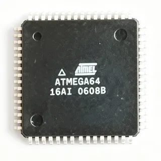
ATMEGA16-16AU - 8-bit AVR MCU 16MHz 16KB Flash TQFP-44 | Microchip
料号: ATMEGA16-16AU ✓ 量产中| 数量 | 单价 | 小计 |
|---|---|---|
| 1 | $6.78 | $6.78 |
| 10 | $6.1 | $61.00 |
| 100 | $5.45 | $545.00 |
| 500 | $4.9 | $2,450.00 |
| 1,000 | $4.41 | $4,410.00 |
ATMEGA16-16AU 概述
A microcontroller unit (MCU) is a single integrated circuit that combines a processor core, memory, and programmable peripherals into one chip, sitting at the heart of embedded systems. The ATmega family belongs to the 8-bit MCU hierarchy within the broader microcontroller and semiconductor taxonomy, and is programmed in-system via SPI or through JTAG with tools such as AVR Studio / Microchip Studio and the open-source MightyCore Arduino hardware package.
Key features include the AVR advanced RISC architecture with 133 powerful instructions, most executing in a single clock cycle; 32 x 8-bit general purpose working registers; 16KB of self-programmable Flash with 10,000 erase/write cycles; three flexible timers/counters with compare modes and PWM; and a hardware two-wire interface (I2C) plus SPI and UART for serial communication. The 10-bit ADC resolves 8 single-ended channels, suiting analog sensor front-ends.
Technically, the -16 speed grade runs up to 16MHz from a 4.5V to 5.5V supply, with operation down to 2.7V at reduced clock speed. Internal RC oscillators, brown-out detection, power-on reset, and idle/power-down power-saving modes reduce external component count. The 32 I/O lines are grouped into four 8-bit ports (PA-PD) with internal pull-ups.
Typical applications include motor control, industrial sensor systems, LED display drivers, and educational/hobby embedded platforms. Design consideration: keep clock frequency within the voltage-derated safe operating region and place 0.1uF decoupling capacitors close to each VCC/AVCC pin. This page synthesizes distributor pricing, drop-in alternatives, and practical design notes not found in the manufacturer datasheet.
直接替换替代料: ATMEGA16-16AU ——相同封装,引脚兼容。需要 PCB 改动的不同封装料号已排除。
本系列中的变体
可与以下型号直接替换的同系列型号: ATMEGA16-16AU (相同外形与封装尺寸) ——差异在于 Instruction Set, Operating Temperature, Maximum Clock Frequency, Debug Interface, Throughput.
快速对比工具——选择替代料号进行并排对比:
ATMEGA16A-AU
✅ 直接替换✓ 有现货
$2.05 / 个
查看数据手册 →ATMEGA32A-AU
✅ 直接替换 ⚠️ 规格未核验✓ 有现货
$2.95 / 个
查看数据手册 →ATMEGA164A-AU
✅ 直接替换 ⚠️ 规格未核验✓ 有现货
$2.65 / 个
查看数据手册 →ATMEGA164PA-AU
✅ 直接替换 ⚠️ 规格未核验✓ 有现货
$2.75 / 个
查看数据手册 →ATMEGA8535-16AU
✅ 直接替换 ⚠️ 规格未核验✓ 有现货
$4.41 / 个
查看数据手册 →ATMEGA162-16AU
✅ 直接替换 ⚠️ 规格未核验✓ 有现货
$2.45 / 个
查看数据手册 →ATMEGA16-16AU 最大额定值与电气特性
| Core Architecture | 8-bit AVR RISC |
| Max Clock Frequency | 16 MHz |
| Flash Memory | 16 KB (8K x 16) in-system programmable |
| SRAM | 1 KB |
| EEPROM | 512 B |
| Supply Voltage Range | 2.7 V to 5.5 V (4.5 V to 5.5 V for 16 MHz operation) |
| Performance | 16 MIPS at 16 MHz |
| Instruction Set | 133 instructions, most single-cycle |
| General Purpose Registers | 32 x 8-bit |
| I/O Pins | 32 |
| ADC | 8-channel, 10-bit |
| Timers/Counters | 3 (two 8-bit, one 16-bit with PWM) |
| Communication Interfaces | UART, SPI, TWI (I2C) |
| Debug Interface | JTAG (on-chip debug) |
| 工作温度 | -40C to +85C |
| 封装 | 44-TQFP (10 x 10 mm) |
| 安装类型 | Surface Mount |
| 生命周期状态 | Active |
ATMEGA16-16AU 44-tqfp (10 x 10 mm) 引脚配置指南
ATMEGA16-16AU(44-tqfp (10 x 10 mm) 封装)的引脚配置。 该数字 IC 包含 GPIO、通信接口(UART、SPI、I2C)和电源引脚。请参阅制造商数据手册以了解复用引脚功能和配置选项。对嵌入式系统设计和 PCB 布局至关重要。

暂无详细引脚数据: ATMEGA16-16AU.
请参阅 数据手册 以查看完整引脚配置。
典型应用
ATMEGA16-16AU 适用于 6 应用s: Motor Control, Industrial Sensor Systems, LED Display and Signage Control, Education and Embedded Prototyping, Consumer Appliance Control Panels, Data Acquisition and Test Fixtures.
Motor Control
The ATMEGA16-16AU fits motor control because its 16-bit Timer/Counter1 provides two hardware compare channels with non-inverting/inverting PWM outputs at up to 16MHz resolution, while Timer2 offers an independent PWM channel for a second actuator. In a DC motor drive, Timer1 generates a 20kHz PWM from a 16MHz clock with 8-bit duty resolution, and the 8-channel 10-bit ADC samples current-shunt and potentiometer feedback for closed-loop PID control at kilohertz rates. Running from a 5V rail at 4.5V to 5.5V guarantees the full 16 MIPS throughput. JTAG on-chip debugging lets engineers halt the control loop and inspect variables in-circuit. A gate driver (e.g., IRS2110 or IR2110) is recommended between the MCU PWM outputs and the power MOSFET bridge.
推荐
Industrial Sensor Systems
The ATMEGA16-16AU is well suited to multi-channel industrial sensing because its 8-channel 10-bit ADC reads up to eight analog sensors (temperature, pressure, humidity) without an external multiplexer, and the 1KB SRAM plus 512B EEPROM support small data logging and calibration constants that survive power cycling. The TWI (I2C) interface connects digital sensors and EEPROMs, while the UART streams readings to SCADA or PLC gateways at standard baud rates. Operating from -40C to +85C covers industrial cabinets, and brown-out detection plus the internal 1MHz/8MHz RC oscillator keep timing functional during supply disturbances. Place a precision voltage reference (e.g., 2.5V) on the AREF pin and decouple AVCC to achieve repeatable ADC readings near the datasheet 10-bit accuracy.
推荐
LED Display and Signage Control
The ATMEGA16-16AU drives LED matrix and 7-segment displays efficiently because all 32 GPIO are available for parallel display scanning - four full 8-bit ports can directly bit-bang a column/row multiplexed matrix, while hardware SPI at up to fosc/2 clocks shift-register drivers such as 74HC595 chains at high speed. Timer0 can generate the multiplexing interrupt (typically 1kHz refresh per row for flicker-free 8-row displays), leaving CPU headroom from the 16 MIPS throughput for animation and communication. At 16MHz and 5V the 20mA-class port sink/source capability directly drives small LED digits through current-limiting resistors. For larger signs, add constant-current LED drivers to offload current from the MCU ports.
推荐
Education and Embedded Prototyping
The ATMEGA16-16AU is a staple of embedded-systems education because the AVR RISC architecture is simple to teach - 133 mostly single-cycle instructions and 32 registers map cleanly to assembly coursework - and the chip includes on-chip JTAG debugging, letting students set breakpoints without extra silicon. The MightyCore Arduino hardware package on GitHub supports ATmega16 boards, so learners can use Arduino APIs with a custom core, or program via SPI ISP with a USBasp programmer. The 5V logic matches breadboard-friendly modules, and the 16MHz/16 MIPS performance handles UART bootloader use. A minimum system needs only a 16MHz crystal with two 22pF capacitors, a 10kOhm RESET pull-up, and 0.1uF decoupling on VCC and AVCC.
推荐
Consumer Appliance Control Panels
The ATMEGA16-16AU serves appliance control panels (washing machines, ovens, HVAC thermostats) because its 32 I/O lines handle many keys, LEDs, relays, and a segment display simultaneously without port expanders. Timer2 can run asynchronously from a 32.768kHz watch crystal on TOSC1/TOSC2 (PC6/PC7), providing an accurate real-time clock while the CPU sleeps in power-save mode - a decisive feature for cost-sensitive appliances that must keep time at low standby power. The 512B EEPROM stores user settings, and the TWI interface reads external NTC/EEPROM peripherals. Robustness features including power-on reset, brown-out detection, and internal RC oscillator options reduce external BOM cost at volume.
推荐
Data Acquisition and Test Fixtures
The ATMEGA16-16AU works well in low-speed data acquisition fixtures where its 10-bit ADC, hardware UART, and JTAG debug cover the full signal chain in one chip. Sampling up to 8 analog channels, the ADC supports roughly 15kSPS at full 10-bit resolution - adequate for temperature, strain-gauge (with instrumentation amplifier), and slow process signals - while the UART streams frames to a PC at 115200 baud. The 1KB SRAM buffers sample blocks between transmissions. The 16MHz crystal option provides deterministic timing for trigger generation. For higher accuracy, drive AREF from an external precision reference and average multiple samples in firmware; keep analog traces away from the crystal and JTAG lines to protect signal integrity.
推荐
推荐产品汇总
工程参考数据: ATMEGA16-16AU ——对比、设计指导和合规信息。
选型指南
与替代料对比
| 参数 | 本产品 | ATMEGA16A-AU | ATMEGA32A-AU | ATMEGA164A-AU | ATMEGA8535-16AU |
|---|---|---|---|---|---|
| Package | 44-TQFP (10x10 mm) | 44-TQFP (10x10 mm) - same | 44-TQFP (10x10 mm) - same | 44-TQFP (10x10 mm) - same | 44-TQFP (10x10 mm) - same |
| Brand | Microchip Technology | Microchip Technology | Microchip Technology | Microchip Technology | Microchip Technology |
| Flash Memory | 16 KB | 16 KB | 32 KB | 16 KB | 8 KB |
| SRAM | 1 KB | 1 KB | 2 KB | 1 KB | 512 B |
| Max Clock Speed | 16 MHz | 16 MHz | 16 MHz | 20 MHz | 16 MHz |
| Pin Compatibility | ATmega16 TQFP-44 pinout | Pin-to-pin (official drop-in) | Pin-to-pin | Pin-to-pin | Pin-to-pin |
| Firmware Compatibility | ATmega16 register map | Binary-compatible (same register map) | Recompile required | Recompile required (enhanced core) | Recompile required (subset) |
| Debug Interface | JTAG | JTAG | JTAG | debugWIRE (no JTAG) | JTAG |
| Operating Temperature | -40C to +85C | -40C to +85C | -40C to +85C | -40C to +85C | -40C to +85C |
关键差异点
- True binary-compatible official drop-in exists (对比 ATMEGA16A-AU)
- JTAG on-chip debugging and boundary scan (对比 ATMEGA164A-AU)
- Four full 8-bit ports (32 GPIO) in a compact 10x10 mm body (对比 ATmega328P (TQFP-32))
设计说明
Respect the voltage-frequency derating: the ATMEGA16-16AU needs 4.5V to 5.5V to run at 16MHz; at 3.3V the safe maximum clock is around 8MHz. Powering a 16MHz design from a nominal 3.3V rail is a common cause of marginal startup and random resets, especially at cold temperature. Place 0.1uF ceramic capacitors on each VCC pin and on AVCC, with AVCC fed through a low-pass filter (10uH inductor or ferrite bead plus 0.1uF) when ADC accuracy matters. Estimated: at 16MHz and 5V, active current is on the order of 10-15 mA per typical AVR figures - verify against the manufacturer datasheet electrical characteristics.
For the 44-TQFP footprint, use the standard 0.8mm pitch land pattern and keep the crystal (16MHz, two 22pF capacitors) within a few millimeters of XTAL1/XTAL2 with short guarded traces to avoid crosstalk. Route JTAG (TCK, TMS, TDO, TDI on port C) to a header even in production builds - it enables boundary scan and on-chip debugging, and the JTAGEN fuse must be cleared to free PC2-PC5 as GPIO. Pull RESET up with 10kOhm to VCC and expose a programming header for SPI ISP (MOSI/MISO/SCK/RESET on port B).
Fuses are the number-one pitfall: setting clock fuses for an external clock when a crystal is fitted, or enabling CKOPT/low-frequency options incorrectly, can brick the chip so it only recovers with a high-voltage parallel programmer. Also remember that JTAG is enabled by default and claims pins PC2-PC5, so those port bits appear dead until JTAGEN is cleared. When substituting the ATMEGA164A or ATMEGA32A on the same PCB, the register map differs - recompile rather than reprogramming the same hex file.
合规信息
Compliance data not stated in the provided verified web data; consult the official Microchip product page and Material Content Declaration for RoHS/REACH status of the specific date code.