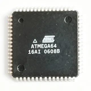
PIC18F458-I/PT - 40MHz 8-Bit CAN Microcontroller | Microchip
料号: PIC18F458-I/PT ✓ 量产中PIC18F458-I/PT 概述
A microcontroller is a programmable integrated circuit containing a processor core, nonvolatile program memory, data memory, and dedicated peripherals. The PIC18F458 belongs to the PIC18 family of 8-bit embedded controllers, a form of embedded processor used to supervise sensors, actuators, communications, and user interfaces. Its flash-based program memory permits field programming and supports the self-programming capability identified for the device family.
The PIC18F458-I/PT combines a maximum operating frequency of 40 MHz with 32 KB of flash memory and 1.5 KB of RAM. Its 34 I/O pins provide interfaces for digital control signals, while the integrated peripherals reduce the need for external components. A watchdog timer, power-on reset, brown-out detection and reset, and low-voltage detection support reliable operation in embedded control systems.
The controller includes a CAN 2.0B module with three transmit buffers, two receive buffers, six full acceptance filters, and two filter masks. This resource is useful for industrial and automotive-style distributed control networks where a microcontroller must exchange prioritized messages over a shared CAN bus. The eight-channel, 10-bit ADC supports analog measurement, while the five-channel, 10-bit PWM output supports motor, lighting, and proportional control functions.
Typical uses include industrial controllers, CAN-connected monitoring equipment, automotive subsystems, data acquisition units, motor-control boards, and compact embedded products. The 44-TQFP package provides enough pins for mixed analog and digital interfaces while remaining suitable for automated board assembly and multilayer PCB layouts.
The primary design constraint is operating voltage: the manufacturer documentation must be consulted for the exact VDD range, clock configuration, ADC conversion characteristics, and peripheral operating limits before schematic release. Firmware should also include watchdog recovery, brown-out-aware startup behavior, and validation of CAN bit timing for the selected oscillator and bus topology.
This product page consolidates the key architecture, memory, peripheral, package, comparison, and design information engineers need to evaluate the PIC18F458-I/PT, while also highlighting the distinctions among closely related PIC18F devices that must be checked before replacement or firmware reuse.
直接替换替代料: PIC18F458-I/PT ——相同封装,引脚兼容。需要 PCB 改动的不同封装料号已排除。
本系列中的变体
可与以下型号直接替换的同系列型号: PIC18F458-I/PT (相同外形与封装尺寸) ——差异在于 Package, Operating Temperature, Timers, ADC, CAN Module.
PIC18F458-E/PT
✅ 直接替换联系询价
查看数据手册 →PIC18F4520-I/PT
✅ 直接替换联系询价
查看数据手册 →PIC18F4580-I/PT
✅ 直接替换📋 参考替代料(不在目录中)
PIC18F458-I/PT 最大额定值与电气特性
| Product Type | 8-bit flash PIC microcontroller |
| Maximum Core Clock | 40 MHz |
| Flash Program Memory | 32 KB |
| Flash Memory Organization | 16K x 16 |
| RAM | 1.5 KB |
| Digital I/O Pins | 34 pins |
| 封装 | 44-TQFP (10 x 10 mm) |
| 安装类型 | Surface mount |
| CAN Protocol | CAN 2.0B |
| CAN Transmit Buffers | 3 |
| CAN Receive Buffers | 2 |
| CAN Acceptance Filters | 6 full acceptance filters and 2 filter masks |
| ADC Resolution | 10-bit |
| ADC Channels | 8 channels |
| PWM Resolution | 10-bit |
| PWM Channels | 5 channels |
| Program Memory Type | Enhanced flash |
| Self-Programming | Supported |
| Watchdog Timer | Integrated |
| Power-On Reset | Integrated POR |
| Brown-Out Detection and Reset | Integrated brown-out detector and reset |
| Low-Voltage Detection | Integrated LVD |
PIC18F458-I/PT 44-tqfp (10 x 10 mm) 引脚配置指南
PIC18F458-I/PT(44-tqfp (10 x 10 mm) 封装)的引脚配置。 该数字 IC 包含 GPIO、通信接口(UART、SPI、I2C)和电源引脚。请参阅制造商数据手册以了解复用引脚功能和配置选项。对嵌入式系统设计和 PCB 布局至关重要。

暂无详细引脚数据: PIC18F458-I/PT.
请参阅 数据手册 以查看完整引脚配置。
典型应用
PIC18F458-I/PT 适用于 6 应用s: Industrial CAN Monitoring Controller, Automotive CAN Subsystem, Eight-Channel Data Acquisition Unit, PWM Motor and Valve Controller, Embedded Sensor Hub, Programmable Logic Controller.
Industrial CAN Monitoring Controller
The PIC18F458-I/PT fits an industrial CAN monitoring node because its CAN 2.0B controller includes three transmit buffers, two receive buffers, six full acceptance filters, and two filter masks. This allows the controller to prioritize messages and reject traffic that does not match configured identifiers. Its 40 MHz core provides ample instruction throughput for local filtering and diagnostics, while 34 I/O pins support digital inputs, discrete outputs, status LEDs, and communication isolation controls. Use an appropriate external CAN transceiver, verify bit timing for the network clock and oscillator configuration, and test termination, bus fault recovery, and watchdog behavior in the final system.
推荐
Automotive CAN Subsystem
The PIC18F458-I/PT is suitable for compact CAN-based automotive subsystems where local control and message filtering are required. Its three CAN transmit buffers and two receive buffers support prioritized communication, while the 32 KB flash and 1.5 KB RAM allow protocol handling, diagnostics, and application logic to coexist. The 34 I/O pins can connect sensors, switches, drivers, and fault indicators. Before deployment, verify the grade limits, automotive qualification requirements, CAN transceiver behavior, bus protection, and transient immunity against the vehicle electrical specification. Firmware should exercise reset, bus-off, and watchdog recovery paths.
推荐
Eight-Channel Data Acquisition Unit
The eight-channel, 10-bit ADC in the PIC18F458-I/PT supports compact analog measurement systems such as environmental, process, and equipment-monitoring units. At a maximum core frequency of 40 MHz, the controller can sample, scale, filter, and report measurements while managing digital alarms and a communication link. The 1.5 KB RAM provides working space for buffering, and 32 KB of flash holds application and calibration code. Keep analog inputs on their assigned pins, follow the datasheet acquisition and reference recommendations, and validate noise, settling time, input range, and sampling sequence on the completed board.
推荐
PWM Motor and Valve Controller
The five 10-bit PWM channels make the PIC18F458-I/PT appropriate for low- to medium-duty motor, valve, and proportional actuator control. The 40 MHz 8-bit processor can combine PWM generation with limit sensing, interlocks, status reporting, and CAN commands. Its 34 I/O pins provide flexibility for direction controls, fault inputs, and discrete sensors. Drive external transistors or motor drivers rather than powering loads directly from microcontroller pins, and account for inductive transients, flyback paths, thermal dissipation, and timing accuracy. Validate startup behavior, stalled-load response, and safety shutdown behavior under worst-case conditions.
推荐
Embedded Sensor Hub
The PIC18F458-I/PT can act as a compact sensor hub for industrial or building systems that combine digital inputs, analog measurements, and CAN reporting. Thirty-four I/O pins allow connection of switches, encoders, discrete sensors, and alarm outputs, while the 8-bit CPU supports local filtering and event logic. The 32 KB flash and 1.5 KB RAM make the device appropriate for protocol stacks and moderate data buffering. Power the sensing interface with appropriate filtering and grounding, define safe states for external inputs, and use the watchdog to recover from unexpected firmware or peripheral faults.
推荐
Programmable Logic Controller
The PIC18F458-I/PT is suitable for compact programmable logic controller designs combining discrete I/O, analog monitoring, PWM outputs, and CAN communications. The 40 MHz core provides deterministic handling of scan tasks, while 32 KB of flash accommodates structured application code and 1.5 KB of RAM supports state variables and communication buffers. Brown-out detection, power-on reset, watchdog timing, and low-voltage detection help support dependable field operation. Establish input filtering, output interlock behavior, communication timeout actions, and safe-state rules in firmware, then verify them against the specific machinery or process being controlled.
推荐
推荐产品汇总
工程参考数据: PIC18F458-I/PT ——对比、设计指导和合规信息。
选型指南
与替代料对比
| 参数 | 本产品 | PIC18F458-E/PT | PIC18F4520-I/PT | PIC18F4580-I/PT |
|---|---|---|---|---|
| Brand | Microchip Technology | Microchip Technology | Microchip Technology | Microchip Technology |
| Package | 44-TQFP (10 x 10 mm) | 44-TQFP (10 x 10 mm) | 44-TQFP (10 x 10 mm) | 44-TQFP (10 x 10 mm) |
| Temperature-Grade Suffix | -I industrial grade | -E extended-temperature grade | -I industrial grade | -I industrial grade |
关键差异点
- Combines CAN 2.0B and flash execution in an 8-bit control device (对比 PIC18F4580-I/PT)
- Industrial temperature ordering option (对比 PIC18F458-E/PT)
- Full 32 KB flash and 34 I/O pins in the same 10 x 10 mm footprint (对比 PIC18F4520-I/PT)
设计说明
Confirm the manufacturer-specified VDD range, decoupling requirements, and brown-out thresholds before finalizing the power tree. Place the required input and bulk capacitors close to the corresponding supply pins, and route high-current return paths away from ADC inputs and oscillator circuitry. Because the available technical summary confirms integrated POR, brown-out reset, and low-voltage detection but does not list exact voltage limits, use the PIC18F458 family datasheet for the authoritative supply values.
Assign the 44-pin TQFP footprint from the manufacturer package drawing and verify every signal against the device-specific pin table before PCB release. Keep decoupling, oscillator components, programming interfaces, and reset circuitry close to their associated pins. Preserve a clean return path beneath sensitive analog sections, isolate CAN transceiver routing from precision analog inputs, and test programming and debug access after final placement.
Do not treat a shared 44-TQFP package as proof of firmware-compatible interchangeability. PIC18F4520-I/PT and PIC18F4580-I/PT are related devices, but the target name, configuration bits, peripheral multiplexing, and application code must be checked individually. For PIC18F458-E/PT, verify that the -E temperature grade remains within the final product's environmental requirement. Build a new project for the final selected device and perform programming, peripheral, and timing regression tests.
For CAN designs, calculate bit timing from the actual oscillator frequency and validate the controller configuration across temperature and supply tolerance. Include the external transceiver, bus termination, fault handling, and protected routing in system testing. The controller's three transmit buffers, two receive buffers, six acceptance filters, and two masks support message management, but correct filter configuration and bus timing remain essential to preventing frame errors and unexpected bus activity.
合规信息
No explicit compliance declarations were stated in the technical source material. Verify RoHS, REACH, lead-free, halogen-free, conflict-minerals, and automotive qualification status using the current manufacturer product documentation before release.