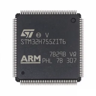
STM32H753BGT6 - 32-bit Arm Cortex-M7 MCU 2MB Flash | STMicroelectronics
料号: STM32H753BGT6 ✓ 量产中| 数量 | 单价 | 小计 |
|---|---|---|
| 1 | $18.5 | $18.50 |
| 10 | $16.8 | $168.00 |
| 100 | $14.2 | $1,420.00 |
| 500 | $12.9 | $6,450.00 |
| 1,000 | $11.5 | $11,500.00 |
STM32H753BGT6 概述
A microcontroller (MCU) is a compact integrated circuit designed to govern a specific operation in an embedded system. It contains a processor core, memory, and programmable input/output peripherals. The STM32H753BGT6 belongs to the STM32H7 series, which is part of the broader STM32 family of 32-bit flash microcontrollers. This family is widely used in applications requiring high computational performance, rich connectivity, and real-time control.
Key features of the STM32H753BGT6 include a 480 MHz Arm Cortex-M7 core with double-precision floating-point unit (FPU), 2 MB of dual-bank flash memory, 1 MB of SRAM, and a comprehensive set of peripherals including multiple 16-bit and 32-bit timers, 12-bit ADCs, DACs, and a camera interface. It also supports advanced connectivity with USB OTG, Ethernet MAC, and multiple SPI, I2C, and UART interfaces. The device includes a Chrom-ART Accelerator for graphics and a hardware cryptographic engine for secure communications.
The STM32H753BGT6 is built on a high-performance architecture that combines the Cortex-M7 core with a sophisticated memory system, including an L1 cache and a TCM (Tightly Coupled Memory) interface. This architecture enables efficient execution of complex algorithms and real-time data processing. The device also features a power management unit with multiple low-power modes, making it suitable for battery-powered applications.
Typical applications include industrial automation, motor control, robotics, medical devices, and high-end audio equipment. The high clock speed and rich peripheral set make it ideal for applications requiring fast data processing and real-time control. The device also supports a wide range of development tools, including the STM32CubeIDE and HAL libraries, which accelerate firmware development.
When designing with the STM32H753BGT6, ensure proper decoupling of the power supply pins and adequate grounding for the LQFP package. The device requires a stable clock source, typically a 25 MHz crystal, and careful PCB layout to minimize noise and ensure reliable operation. The internal voltage regulator can be configured for different performance modes, balancing power consumption and performance.
直接替换替代料: STM32H753BGT6 ——相同封装,引脚兼容。需要 PCB 改动的不同封装料号已排除。
本系列中的变体
可与以下型号直接替换的同系列型号: STM32H753BGT6 (相同外形与封装尺寸) ——差异在于 Communication Interfaces, Flash Memory, Package, SRAM, ADC Resolution.
快速对比工具——选择替代料号进行并排对比:
STM32H743BGT6
✅ 直接替换✓ 有现货
$12.4 / 个
查看数据手册 →STM32H753BIT6
✅ 直接替换📋 参考替代料(不在目录中)
STM32H750BGT6
✅ 直接替换 ⚠️ 规格未核验📋 参考替代料(不在目录中)
STM32H753BGT6
✅ 直接替换✓ 有现货
$11.5 / 个
查看数据手册 →STM32H743BGT6
✅ 直接替换✓ 有现货
$12.4 / 个
查看数据手册 →STM32H753BIT6
✅ 直接替换📋 参考替代料(不在目录中)
STM32H750BGT6
✅ 直接替换 ⚠️ 规格未核验📋 参考替代料(不在目录中)
STM32H753BGT6
✅ 直接替换✓ 有现货
$11.5 / 个
查看数据手册 →STM32H743BGT6
✅ 直接替换✓ 有现货
$12.4 / 个
查看数据手册 →STM32H753BIT6
✅ 直接替换📋 参考替代料(不在目录中)
STM32H750BGT6
✅ 直接替换 ⚠️ 规格未核验📋 参考替代料(不在目录中)
STM32H753BGT6
✅ 直接替换✓ 有现货
$11.5 / 个
查看数据手册 →STM32H743BGT6
✅ 直接替换✓ 有现货
$12.4 / 个
查看数据手册 →STM32H753BIT6
✅ 直接替换📋 参考替代料(不在目录中)
STM32H750BGT6
✅ 直接替换 ⚠️ 规格未核验📋 参考替代料(不在目录中)
STM32H753BGT6
✅ 直接替换✓ 有现货
$11.5 / 个
查看数据手册 →STM32H743BGT6
✅ 直接替换✓ 有现货
$12.4 / 个
查看数据手册 →STM32H753BIT6
✅ 直接替换📋 参考替代料(不在目录中)
STM32H750BGT6
✅ 直接替换 ⚠️ 规格未核验📋 参考替代料(不在目录中)
STM32H753BGT6
✅ 直接替换✓ 有现货
$11.5 / 个
查看数据手册 →STM32H753BGT6 最大额定值与电气特性
| Core | Arm Cortex-M7 |
| 最大时钟频率 | 480 MHz |
| Flash Memory | 2 MB |
| SRAM | 1 MB |
| Supply Voltage Range | 1.62 V to 3.6 V |
| 封装 | LQFP-144 (20x20 mm) |
| 工作温度范围 | -40C to +85C |
| Number of I/O Pins | 114 |
| ADC Resolution | 12-bit |
| Number of ADC Channels | 3x 12-bit ADC with up to 16 channels each |
| DAC Resolution | 12-bit |
| Number of Timers | 22 (including 2x 32-bit timers) |
| Communication Interfaces | USB OTG, Ethernet MAC, SPI, I2C, UART, CAN, SAI |
| Cryptographic Acceleration | Hardware AES, DES, 3DES, SHA-1, SHA-256 |
| RoHS 状态 | Compliant |
STM32H753BGT6 引脚配置
| 引脚 1 | PE2 — GPIO or alternate function |
| 引脚 2 | PE3 — GPIO or alternate function |
| 引脚 3 | PE4 — GPIO or alternate function |
| 引脚 4 | PE5 — GPIO or alternate function |
| 引脚 5 | PE6 — GPIO or alternate function |
| 引脚 6 | VBAT — Backup battery supply |
| 引脚 7 | PC13 — GPIO or RTC output |
| 引脚 8 | PC14 — GPIO or OSC32_IN |
| 引脚 9 | PC15 — GPIO or OSC32_OUT |
| 引脚 10 | PF0 — GPIO or alternate function |
| 引脚 11 | PF1 — GPIO or alternate function |
| 引脚 12 | PF2 — GPIO or alternate function |
| 引脚 13 | PF3 — GPIO or alternate function |
| 引脚 14 | PF4 — GPIO or alternate function |
| 引脚 15 | PF5 — GPIO or alternate function |
| 引脚 16 | PF6 — GPIO or alternate function |
| 引脚 17 | PF7 — GPIO or alternate function |
| 引脚 18 | PF8 — GPIO or alternate function |
| 引脚 19 | PF9 — GPIO or alternate function |
| 引脚 20 | PF10 — GPIO or alternate function |
| 引脚 21 | PF11 — GPIO or alternate function |
| 引脚 22 | PF12 — GPIO or alternate function |
| 引脚 23 | PF13 — GPIO or alternate function |
| 引脚 24 | PF14 — GPIO or alternate function |
| 引脚 25 | PF15 — GPIO or alternate function |
| 引脚 26 | PG0 — GPIO or alternate function |
| 引脚 27 | PG1 — GPIO or alternate function |
| 引脚 28 | PG2 — GPIO or alternate function |
| 引脚 29 | PG3 — GPIO or alternate function |
| 引脚 30 | PG4 — GPIO or alternate function |
| 引脚 31 | PG5 — GPIO or alternate function |
| 引脚 32 | PG6 — GPIO or alternate function |
| 引脚 33 | PG7 — GPIO or alternate function |
| 引脚 34 | PG8 — GPIO or alternate function |
| 引脚 35 | PG9 — GPIO or alternate function |
| 引脚 36 | PG10 — GPIO or alternate function |
| 引脚 37 | PG11 — GPIO or alternate function |
| 引脚 38 | PG12 — GPIO or alternate function |
| 引脚 39 | PG13 — GPIO or alternate function |
| 引脚 40 | PG14 — GPIO or alternate function |
| 引脚 41 | PG15 — GPIO or alternate function |
| 引脚 42 | PH0 — GPIO or OSC_IN |
| 引脚 43 | PH1 — GPIO or OSC_OUT |
| 引脚 44 | PH2 — GPIO or alternate function |
| 引脚 45 | PH3 — GPIO or alternate function |
| 引脚 46 | PH4 — GPIO or alternate function |
| 引脚 47 | PH5 — GPIO or alternate function |
| 引脚 48 | PH6 — GPIO or alternate function |
| 引脚 49 | PH7 — GPIO or alternate function |
| 引脚 50 | PH8 — GPIO or alternate function |
| 引脚 51 | PH9 — GPIO or alternate function |
| 引脚 52 | PH10 — GPIO or alternate function |
| 引脚 53 | PH11 — GPIO or alternate function |
| 引脚 54 | PH12 — GPIO or alternate function |
| 引脚 55 | PH13 — GPIO or alternate function |
| 引脚 56 | PH14 — GPIO or alternate function |
| 引脚 57 | PH15 — GPIO or alternate function |
| 引脚 58 | PI0 — GPIO or alternate function |
| 引脚 59 | PI1 — GPIO or alternate function |
| 引脚 60 | PI2 — GPIO or alternate function |
| 引脚 61 | PI3 — GPIO or alternate function |
| 引脚 62 | PI4 — GPIO or alternate function |
| 引脚 63 | PI5 — GPIO or alternate function |
| 引脚 64 | PI6 — GPIO or alternate function |
| 引脚 65 | PI7 — GPIO or alternate function |
| 引脚 66 | PI8 — GPIO or alternate function |
| 引脚 67 | PI9 — GPIO or alternate function |
| 引脚 68 | PI10 — GPIO or alternate function |
| 引脚 69 | PI11 — GPIO or alternate function |
| 引脚 70 | PI12 — GPIO or alternate function |
| 引脚 71 | PI13 — GPIO or alternate function |
| 引脚 72 | PI14 — GPIO or alternate function |
| 引脚 73 | PI15 — GPIO or alternate function |
| 引脚 74 | PA0 — GPIO or alternate function |
| 引脚 75 | PA1 — GPIO or alternate function |
| 引脚 76 | PA2 — GPIO or alternate function |
| 引脚 77 | PA3 — GPIO or alternate function |
| 引脚 78 | PA4 — GPIO or alternate function |
| 引脚 79 | PA5 — GPIO or alternate function |
| 引脚 80 | PA6 — GPIO or alternate function |
| 引脚 81 | PA7 — GPIO or alternate function |
| 引脚 82 | PA8 — GPIO or alternate function |
| 引脚 83 | PA9 — GPIO or alternate function |
| 引脚 84 | PA10 — GPIO or alternate function |
| 引脚 85 | PA11 — GPIO or alternate function |
| 引脚 86 | PA12 — GPIO or alternate function |
| 引脚 87 | PA13 — GPIO or SWDIO |
| 引脚 88 | PA14 — GPIO or SWCLK |
| 引脚 89 | PA15 — GPIO or alternate function |
| 引脚 90 | PB0 — GPIO or alternate function |
| 引脚 91 | PB1 — GPIO or alternate function |
| 引脚 92 | PB2 — GPIO or alternate function |
| 引脚 93 | PB3 — GPIO or alternate function |
| 引脚 94 | PB4 — GPIO or alternate function |
| 引脚 95 | PB5 — GPIO or alternate function |
| 引脚 96 | PB6 — GPIO or alternate function |
| 引脚 97 | PB7 — GPIO or alternate function |
| 引脚 98 | PB8 — GPIO or alternate function |
| 引脚 99 | PB9 — GPIO or alternate function |
| 引脚 100 | PB10 — GPIO or alternate function |
| 引脚 101 | PB11 — GPIO or alternate function |
| 引脚 102 | PB12 — GPIO or alternate function |
| 引脚 103 | PB13 — GPIO or alternate function |
| 引脚 104 | PB14 — GPIO or alternate function |
| 引脚 105 | PB15 — GPIO or alternate function |
| 引脚 106 | PD0 — GPIO or alternate function |
| 引脚 107 | PD1 — GPIO or alternate function |
| 引脚 108 | PD2 — GPIO or alternate function |
| 引脚 109 | PD3 — GPIO or alternate function |
| 引脚 110 | PD4 — GPIO or alternate function |
| 引脚 111 | PD5 — GPIO or alternate function |
| 引脚 112 | PD6 — GPIO or alternate function |
| 引脚 113 | PD7 — GPIO or alternate function |
| 引脚 114 | PD8 — GPIO or alternate function |
| 引脚 115 | PD9 — GPIO or alternate function |
| 引脚 116 | PD10 — GPIO or alternate function |
| 引脚 117 | PD11 — GPIO or alternate function |
| 引脚 118 | PD12 — GPIO or alternate function |
| 引脚 119 | PD13 — GPIO or alternate function |
| 引脚 120 | PD14 — GPIO or alternate function |
| 引脚 121 | PD15 — GPIO or alternate function |
| 引脚 122 | PE0 — GPIO or alternate function |
| 引脚 123 | PE1 — GPIO or alternate function |
| 引脚 124 | VDD — Power supply |
| 引脚 125 | VSS — Ground |
| 引脚 126 | VDD — Power supply |
| 引脚 127 | VSS — Ground |
| 引脚 128 | VDD — Power supply |
| 引脚 129 | VSS — Ground |
| 引脚 130 | VDD — Power supply |
| 引脚 131 | VSS — Ground |
| 引脚 132 | VDD — Power supply |
| 引脚 133 | VSS — Ground |
| 引脚 134 | VDD — Power supply |
| 引脚 135 | VSS — Ground |
| 引脚 136 | VDD — Power supply |
| 引脚 137 | VSS — Ground |
| 引脚 138 | VDD — Power supply |
| 引脚 139 | VSS — Ground |
| 引脚 140 | VDD — Power supply |
| 引脚 141 | VSS — Ground |
| 引脚 142 | VDD — Power supply |
| 引脚 143 | VSS — Ground |
| 引脚 144 | VDD — Power supply |
典型应用
STM32H753BGT6 适用于 6 应用s: Industrial Automation, Motor Control, Medical Devices, High-End Audio Equipment, Robotics, IoT Gateways.
Industrial Automation
The STM32H753BGT6 is ideal for industrial automation due to its high clock speed (480 MHz) and rich peripheral set. It can handle complex control algorithms, real-time communication (Ethernet, CAN), and multiple sensor inputs. The hardware cryptographic engine ensures secure data transmission in industrial IoT applications. Its wide operating temperature range and robust design make it suitable for factory floor environments.
推荐
Motor Control
The STM32H753BGT6 excels in motor control applications, providing high-resolution PWM generation, multiple ADCs for current sensing, and advanced timers. Its 480 MHz core enables fast execution of field-oriented control (FOC) algorithms, improving efficiency and dynamic response. The device supports various motor types, including BLDC, PMSM, and AC induction motors. The integrated hardware cryptographic engine can secure firmware updates and communication in motor drives.
推荐
Medical Devices
The STM32H753BGT6 is suitable for medical devices such as patient monitors, infusion pumps, and diagnostic equipment. Its high performance enables real-time signal processing and graphical user interfaces. The hardware cryptographic engine ensures secure patient data handling, complying with healthcare regulations. The device's low-power modes help extend battery life in portable medical devices.
推荐
High-End Audio Equipment
The STM32H753BGT6 is used in high-end audio equipment such as digital audio players, AV receivers, and professional audio interfaces. Its high clock speed and DSP capabilities enable advanced audio processing, including noise reduction and equalization. The device supports multiple audio interfaces (SAI, I2S) and can handle high-resolution audio formats. The Chrom-ART Accelerator enhances graphical user interfaces on audio devices.
推荐
Robotics
The STM32H753BGT6 is well-suited for robotics applications, providing high computational power for path planning, sensor fusion, and motor control. Its multiple communication interfaces allow integration with various sensors and actuators. The hardware cryptographic engine secures communication between robots and control systems. The device's real-time capabilities ensure precise and responsive robot movements.
推荐
IoT Gateways
The STM32H753BGT6 is an excellent choice for IoT gateways, offering high performance for data aggregation, protocol conversion, and edge computing. Its Ethernet MAC and USB OTG interfaces enable connectivity to local networks and cloud services. The hardware cryptographic engine ensures secure communication and data integrity. The device's low-power modes help reduce energy consumption in always-on gateway applications.
推荐
推荐产品汇总
工程参考数据: STM32H753BGT6 ——对比、设计指导和合规信息。
选型指南
与替代料对比
| 参数 | 本产品 | STM32H743BGT6 | STM32H753BIT6 | STM32H750BGT6 |
|---|---|---|---|---|
| Package | LQFP-144 | LQFP-144 | LQFP-144 | LQFP-144 |
| Brand | STMicroelectronics | STMicroelectronics | STMicroelectronics | STMicroelectronics |
| Core | Arm Cortex-M7 | Arm Cortex-M7 | Arm Cortex-M7 | Arm Cortex-M7 |
| Maximum Clock Frequency | 480 MHz | 480 MHz | 480 MHz | 480 MHz |
| Flash Memory | 2 MB | 2 MB | 2 MB | 128 KB |
| SRAM | 1 MB | 1 MB | 1 MB | 1 MB |
| Cryptographic Engine | Yes | No | Yes | Yes |
| Operating Temperature Range | -40C to +85C | -40C to +85C | -40C to +125C | -40C to +85C |
关键差异点
- Hardware cryptographic engine (对比 STM32H743BGT6)
- 2 MB dual-bank flash (对比 STM32H750BGT6)
- Industrial temperature grade option (对比 STM32H753BGT6 (standard))
设计说明
The STM32H753BGT6 requires a stable power supply. Use a 100 nF decoupling capacitor on each VDD pin and a 4.7 uF bulk capacitor on the main supply. The VCAP pins require a 2.2 uF capacitor to ground for the internal voltage regulator. Ensure the supply voltage is within 1.62V to 3.6V.
For the LQFP-144 package, ensure proper grounding and thermal relief. Use a solid ground plane and place vias near the ground pins to minimize inductance. The exposed pad (if present) should be soldered to the ground plane for better thermal performance.
Do not leave unused pins floating; configure them as analog inputs or outputs to avoid excessive current consumption. Ensure the boot pins (BOOT0, BOOT1) are set correctly for the desired boot mode. The NRST pin should have a 100 nF capacitor to ground for reliable reset.
合规信息
RoHS compliant per STMicroelectronics product page. Not AEC-Q100 qualified; for automotive, consider STM32H753BIT6Q.