Logic ICs
Products (361)

HEF4047BT - CMOS Monostable/Astable Multivibrator SOIC-14
The Nexperia (formerly NXP Semiconductors) HEF4047BT is a CMOS monostable/astable multivibrator housed in a 14-pin SOIC (SOT108) surface-mount package. It is a retriggerable astable multivibrator that can be configured as either a positive-edge or negative-edge triggered monostable multivibrator, with output pulse width programmed by external resistor Rt and capacitor Ct. The device includes clamp diodes on inputs, enabling the use of current limiting resistors to interface to voltages in excess of VCC. A multivibrator is a fundamental digital timing element that produces pulse waveforms without a stable DC state, or a single controlled-width pulse (monostable) from a trigger event. Within the digital-IC taxonomy, the HEF4047BT sits in the specialty-logic family of CMOS logic ICs, branching from the broader 4000-series CMOS logic line. Its core role in system design is generating precise time delays or square-wave clocks without software overhead, complementing microcontrollers and PLLs in mixed-signal designs. Key features include wide supply voltage operation from 4.5 V to 15.5 V, low quiescent current of typically 2.4 mA, 50 ns propagation delay, monostable and astable modes in a single device, retriggerable operation, and master reset. The SOIC-14 package provides ease of assembly on standard reflow profiles with MSL Level 1 moisture sensitivity. Internally the HEF4047BT uses CMOS logic gates combined with an external RC timing network to set the output pulse width or oscillation frequency. Its high noise immunity (typical of 4000-series CMOS) and low power consumption make it well-suited to battery-powered and industrial environments. The retrigger capability allows the output pulse to be extended by repeated triggers within the timing window. Typical applications include missing-pulse detection, bounce-free switches, frequency discriminators, timing circuits, clock-pulse generation, and monostable multivibrators for digital debounce in industrial controls, instrumentation, and consumer electronics. Engineers often pair it with the CD4013 or CD4093 for cascaded timing chains. When designing with the HEF4047BT, select Rt and Ct to place the timing well within the part's specified range, keep Rt traces short to avoid stray capacitance pickup, and bypass VCC with a 100 nF ceramic capacitor placed close to pin 14. Note that the HEF4047BT,653 reel-pack variant and HEF4047BT,652 bulk-pack variant share identical silicon and pinout. This page synthesizes distributor pricing, drop-in SOIC-14 alternatives, and practical design notes not found in the manufacturer datasheet alone, including cross-vendor substitutes such as CD4047BCN from onsemi and HCF4047 from STMicroelectronics.

HEF4538BT - Dual Monostable Multivibrator | Nexperia SOIC-16
The Nexperia HEF4538BT is a dual retriggerable-resettable monostable multivibrator in a 16-pin SOIC package, providing two independent precision one-shot timing channels per IC. Each multivibrator features an active-LOW trigger/retrigger input (nA), an active-HIGH trigger/retrigger input (nB), an overriding active-LOW direct reset input (nCD), complementary outputs (nQ and nQ-bar), and dedicated pins (nREXT/CEXT and CEXT) for connecting external timing components REXT and CEXT. A monostable multivibrator (one-shot) is a sequential logic building block belonging to the broader multivibrator family, which also includes astable (free-running) and bistable (flip-flop) variants. Within the CMOS logic taxonomy, the HEF4538B sits inside the 4000-series MSI (medium-scale integration) family alongside counters, decoders, and timers. Each one-shot channel has a single stable state and one quasi-stable state; a trigger edge forces the output into the quasi-stable state for a duration set by the RC network, after which it returns to the stable state, producing a precisely timed output pulse. Key features of the HEF4538BT include a wide supply voltage range of 3.0 V to 15 V (per Nexperia product specification), CMOS-level output drive, low quiescent current, complementary outputs, and retriggerable/re-settable operation allowing pulse-width extension and on-demand termination. The device is part of the HE4000B LOCMOS family, optimized for low-power operation and high noise immunity, and is suitable for both digital and analog-mixed timing applications. Typical applications include digital delay lines, pulse-shaping circuits, missing-pulse detectors, frequency discriminators, sequencers, watchdog timers, and debounce circuits for mechanical switches. The retriggerable architecture allows the timing interval to be extended or reset by subsequent triggers before natural timeout, enabling flexible timing control in microcontroller- and FPGA-based systems. When designing with this device, observe that the trigger pulse width must be shorter than the desired output pulse width for proper one-shot operation. Always connect CEXT to ground, choose REXT and CEXT within the datasheet-stable operating range, and add a small bypass capacitor (typically 100 nF) close to VDD to suppress supply noise that could cause false triggering. The HEF4538BT is the -Q100 automotive-qualified variant's foundation, making it a versatile choice for industrial, consumer, and automotive-grade timing designs. This page synthesizes distributor pricing, drop-in alternatives, and practical design notes that go beyond the manufacturer datasheet, helping engineers rapidly evaluate HEF4538BT for new designs and second-source for legacy CD4538/MC14538 installations.

ISO6763QDWRQ1 - 6-CH 50Mbps 5kVrms Digital Isolator | TI
The Texas Instruments ISO6763QDWRQ1 is an automotive-grade, 6-channel (3/3) reinforced digital isolator delivering 50 Mbps data rate, 5000 Vrms isolation per UL 1577, and 100 kV/us common-mode transient immunity (CMTI) in a 16-pin wide-body SOIC (DW) package operating from -40C to +125C. A digital isolator is a semiconductor device that transfers digital signals across an isolation barrier, galvanically separating two ground domains to block high voltages, reject ground loops, and protect low-voltage circuitry. Within the power-signal-chain hierarchy, digital isolators sit under the isolation products family, alongside isolated transceivers and gate drivers, and are foundational components in industrial and automotive power management systems. Key features include the 50 Mbps data rate supporting fast SPI, UART, and general-purpose GPIO traffic, 1.8 V to 5 V logic compatibility on both sides for direct interfacing with modern MCUs, and the 100 kV/us CMTI rating that keeps signals intact in the presence of aggressive switching transients from SiC and IGBT power stages. The AEC-Q100 qualification makes the part suitable for automotive environments. The ISO676x-Q1 family uses TI capacitive isolation technology, with an SiO2-based barrier providing reinforced isolation. The 3/3 channel configuration (three channels in each direction) supports bidirectional buses such as full-duplex SPI (SCLK, MOSI, MISO plus CS) across the barrier without direction-control pins, reducing firmware overhead and glitch risk. The wide-body DW package provides adequate creepage and clearance for reinforced isolation designs. Typical applications include isolated SPI communication in battery management systems (BMS), isolated UART and GPIO in on-board chargers and traction inverters, isolated communication in motor drives, and industrial PLC I/O isolation. Design consideration: verify the total load capacitance on both sides; at 50 Mbps the output drivers need adequate decoupling (100 nF local plus 4.7 uF bulk per side is a common practice) to maintain signal integrity during simultaneous switching of multiple channels. This page synthesizes distributor pricing, drop-in alternatives, and practical design notes not found in the manufacturer datasheet.

LC4032C-5T48I - 400MHz 32-Macrocell ISP CPLD | Lattice
The Lattice Semiconductor LC4032C-5T48I is a 3.3V/2.5V/1.8V in-system programmable SuperFAST high-density PLD with 32 macrocells, a 400MHz maximum operating frequency, and a 2.5ns propagation delay in a TQFP package. The device combines programmable logic, in-system programmability, and high-speed timing in one reconfigurable semiconductor. A CPLD, or complex programmable logic device, is a user-programmable digital logic semiconductor within the broader FPGA and programmable-logic hierarchy. Its interconnected programmable logic blocks provide deterministic timing and flexible implementation of combinational and sequential functions. The LC4032C family is positioned for designs requiring high-density logic, compact integration, and field-reconfigurable control or interface functions. The verified LC4032C-5T48I listing identifies support for 3.3V, 2.5V, and 1.8V operation, up to four global clock pins, programmable clock polarity, and routing to 80 product-term outputs. The 400MHz maximum operating frequency and 2.5ns propagation delay make the device useful where logic timing margin matters. The -5 speed designation and industrial temperature suffix indicate the ordering variant, although detailed electrical limits require the manufacturer datasheet. Typical applications include system control, bus arbitration, protocol-interface glue logic, industrial automation, instrumentation, and embedded control. In a control design, the CPLD can consolidate fixed logic functions while retaining the option to update the configuration when board requirements evolve. In a timing-sensitive interface, the global-clock structure can help distribute registered logic across the device. PCB design should preserve the manufacturer-recommended package footprint and verify every power, ground, clock, and I/O connection against the datasheet pinout. Designers should also account for configuration-control timing, unused pins, supply sequencing, and the specified operating voltage. Programming files, pull resistors, clock requirements, and I/O standards must be checked in the applicable device documentation before release to production. This page consolidates verified manufacturer and distributor references for LC4032C-5T48I, highlights the 32-macrocell and 400MHz positioning, and separates documented facts from parameters requiring engineering confirmation. It is intended to support component identification, sourcing, and design review rather than replace the complete Lattice datasheet.
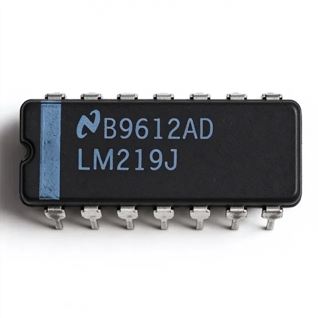
LM219J - High-Speed Dual Comparator | Texas Instruments
The Texas Instruments LM219J is a general-purpose, high-speed dual comparator with two independent comparison channels, a 5 V to 30 V supply range, and a 14-CDIP package. It is designed for applications requiring rapid logic-level decisions and compatibility with DTL, open-collector, open-emitter, RTL, and TTL interfaces. The device is supplied in a 0.300-inch, 7.62 mm ceramic dual-inline package. A comparator is an analog-to-digital decision component that compares two input voltages and produces a logic-oriented output indicating which input is higher. In the broader electronics hierarchy, the LM219J belongs to the comparator and linear IC families, alongside logic-compatible interface and signal-conditioning devices. Its two channels can be used independently for threshold detection, zero-crossing detection, pulse shaping, or basic control loops. The verified LM219J information identifies a dual general-purpose comparator, a 5 V to 30 V supply range, and DTL, open-collector, open-emitter, RTL, and TTL output compatibility. These characteristics make it useful in legacy industrial logic, control, test, and instrumentation systems where existing designs depend on high-voltage-compatible inputs and established logic interfaces. The dual-channel configuration also reduces the component count when two comparison functions are required. The LM219J family is described as a precision high-speed dual comparator fabricated on a single monolithic chip. The verified data does not provide a full electrical parameter table, propagation-delay value, input-offset specification, input-current limit, or output-current rating, so those values are not inferred here. Applications should be checked against the manufacturer datasheet before relying on timing, noise, input common-mode range, or output-drive limits. Typical uses include industrial control logic, digital threshold detection, pulse and signal monitoring, legacy computer interfaces, process-control instrumentation, and embedded systems using open-collector or TTL-compatible signaling. The 14-CDIP package favors through-hole legacy boards and repair or modernization projects rather than compact surface-mount assemblies. When upgrading a PCB, confirm pin numbering, supply polarity, input polarity, output pull-up requirements, and timing margins before substitution. For robust implementation, place the device close to the circuitry whose signals are being compared, maintain the required supply voltage, and observe the output-load requirements of the selected interface. Open-collector outputs generally need an external pull-up network, while TTL-compatible systems may use active drive. PCB layout should minimize long comparator input traces and provide adequate bypassing around the supply pins. This page combines verified distributor and cross-reference information with practical engineering guidance. It explicitly separates available facts from missing parameters so that procurement, replacement, and high-speed circuit decisions can be checked against the authoritative Texas Instruments documentation before design release.

LM2903M - Dual Differential Comparator | Texas Instruments
The Texas Instruments LM2903M is a dual differential comparator in an 8-pin SOIC package. It contains two independent comparator channels, operates from a single supply or split supplies, and provides open-collector output stages suitable for driving external pull-up networks. The verified distributor listing identifies the device as a standard general-purpose comparator with rail-to-rail input capability, while the linked Fairchild datasheet describes the LM2903 family as a dual differential comparator designed for operation from a 2 V to 36 V supply. The LM2903M combines two precision comparators with low input offset voltage, low supply current, and a propagation delay listed by a verified distributor source as 1.5 microseconds. A comparator is a differential amplifier with a logic output rather than a conventional analog output. It evaluates the voltage relationship between its inverting and non-inverting inputs and produces a saturated digital state when the selected input exceeds the reference. In the LM2903M, two independent channels allow one device to perform two threshold decisions, window comparisons, or complementary sensing functions. This makes the part useful as a building block within logic ICs, interface ICs, industrial control systems, and discrete analog signal-conditioning circuits. Key features include dual differential comparison, an open-collector output, single-supply operation from 2 V to 36 V, support for split-supply operation, and an 8-SOIC surface-mount package. The open-collector outputs can be wired to a common pull-up rail when multiple comparators need a shared bus, although the pull-up resistor and external logic voltage must be selected for the intended interface. The reported 1.5 microsecond response time is adequate for many industrial and control applications where the system does not require sub-microsecond decisions. The LM2903 family is designed for low-power operation independent of the supply voltage, which helps conserve energy in battery-powered and distributed equipment. Each channel has independent input and output behavior, allowing one channel to monitor a sensor while the second channel provides an alarm, window-limit, or control function. Input and output behavior should still be checked against the complete manufacturer datasheet for the exact ordering code before production use. Typical applications include battery monitoring, industrial sensor interfaces, overvoltage and undervoltage detection, temperature threshold circuits, power-supply sequencing, and general-purpose logic control. The open-collector output is especially useful when driving a relay, opto-isolator, or another device that requires a pulled-up supply domain. The SOIC-8 footprint is suitable for conventional surface-mount PCB assembly, but the exposed package dimensions and lead geometry should be checked against the mechanical drawing. For a reliable design, begin by verifying the input common-mode range, output sink current, supply-current limits, and propagation delay against the required operating conditions. Do not leave the open-collector outputs without an appropriate pull-up resistor unless the intended load provides one. Decoupling capacitors should be placed close to the supply and ground pins, and input traces should be kept short to reduce noise pickup. This product page combines verified manufacturer and distributor information with engineering guidance, comparison data, and practical design notes to support component selection and PCB implementation.

LM293H - Dual Differential Comparator | Texas Instruments
The Texas Instruments LM293H is a dual differential comparator, an analog comparator IC with two independent comparison channels, open-collector outputs, and a TO-99-8 metal can package. The verified product data identifies the device as a general-purpose, low-power comparator with low offset voltage, operating from single or dual supplies over a wide voltage range. The LM293H is suitable when two signals must be compared and the result must drive TTL, MOS, CMOS, or other digital logic through its open-collector output. A differential comparator is a semiconductor device that compares two input voltages and produces a logic-level indication of their relationship. The dual-channel architecture provides two independent comparators in one package, reducing component count in threshold detection, overvoltage indication, current sensing, and control systems. Its open-collector outputs require an external pull-up resistor when the output must settle to a valid high level. The LM293 family is associated with wide supply capability, single-supply operation, and compatibility with common logic families. The LM293H is identified in the verified distributor data as an 8-pin TO-99-8 device with two channels. The manufacturer family information describes the LM293 as an industrial-grade dual differential comparator. The verified search data specifically lists low power, low offset voltage, rail-to-rail input labeling, open-collector output, and a wide supply operating range. Detailed electrical limits, propagation-delay curves, input common-mode limits, output sink-current limits, and temperature limits must be confirmed in the manufacturer datasheet before final design release. Typical uses include battery-powered monitoring, industrial sensor interfaces, overvoltage detection, temperature threshold circuits, and dual-rail control logic. In a practical design, each comparator can monitor a signal against a reference voltage while the open-collector output drives a pull-up and the downstream logic input. Care is required when inputs approach supply rails, when output pull-up speed affects timing, or when unused comparator channels are left unconnected. This page combines verified manufacturer and distributor links, package identification, application guidance, and structured comparison information. It intentionally avoids filling unavailable electrical values with guesses; consult the current manufacturer datasheet for authoritative limits, ordering details, and lifecycle information.

LMV761MF/NOPB - 120ns Precision Comparator | Texas Instruments
The Texas Instruments LMV761MF/NOPB is a single, low-voltage precision comparator with a 120 ns response time, push-pull output, and shutdown capability. It operates from a 2.7 V to 5 V supply and is packaged in a compact 6-pin SOT-23 package. The device is intended for precision signal conditioning, threshold detection, and low-noise analog systems where fast decision-making and low supply current are important. A comparator is an analog integrated circuit that compares two input voltages and changes its output state when the differential input crosses a defined threshold. Unlike an operational amplifier, a comparator is optimized for saturated digital-style output states rather than linear amplification. The LMV761 belongs to the broader semiconductor hierarchy of analog ICs, comparator circuits, and low-voltage precision signal-conditioning components. The LMV761MF/NOPB provides a single comparator channel with rail-to-rail input capability, push-pull output, and a shutdown pin. Its 120 ns propagation delay supports fast decision paths, while its low supply current makes it suitable for portable and low-power equipment. The push-pull output avoids the external pull-up resistor normally required by open-collector comparators, simplifying PCB layout and reducing system component count. This comparator is particularly useful when a system must convert an analog measurement into a logic-level decision without adding substantial propagation delay. Its 2.7 V minimum supply voltage supports low-voltage digital and embedded systems, while operation up to 5 V provides compatibility with conventional low-voltage rails. The SOT-23-6 package supports compact placement, although designers should account for the small thermal footprint and exposed pad limitations of the package family. Typical applications include sensor threshold detection, battery and power-supply monitoring, signal crossing detection, window-comparison circuits, industrial control logic, portable instrumentation, and low-voltage embedded systems. The shutdown function can reduce supply current when the comparator is not needed, helping conserve power in always-on equipment. For reliable operation, connect the supply and ground pins according to the manufacturer datasheet, place bypass capacitance close to the device, and treat unused input pins carefully. Input common-mode range, output drive capability, and shutdown logic should be verified against the system requirements before layout release. This page summarizes verified manufacturer and distributor information alongside practical selection guidance, drop-in alternatives, and design considerations not consolidated in a single source.

LSF0102-Q1 - 2-Ch Auto Bidirectional Level Translator | TI
The Texas Instruments LSF0102-Q1 is an automotive-qualified, 2-channel auto bidirectional multi-voltage level translator for open-drain and push-pull applications, packaged in an 8-pin VSSOP (DCU). It operates from 0.95 V to 5.5 V on Vref_A and 1.8 V to 5.5 V on Vref_B, enabling bidirectional translation between 0.95 V and 5.5 V without a direction pin. Data inputs are 5-V tolerant. A voltage level translator is a logic IC that converts signal voltage levels between circuits operating at different supply rails, sitting within the broader hierarchy of voltage translators -> logic ICs -> interface semiconductors. The LSF family uses a pass-gate (transmission-gate) architecture with reference rails, distinguishing it from powered translator families such as TXS/TXB that use MOSFET output stages. Key features include up to 100 MHz up translation and greater than 100 MHz down translation with capacitive loads of 30 pF or less; at a 50 pF load the device supports up to 40 MHz in both directions. This bandwidth covers standard automotive interfaces such as I2C, SPI, GPIO, SDIO, UART, and MDIO. AEC-Q100 qualification makes it suitable for automotive environments. The auto-direction architecture requires no direction-control pin, reducing MCU GPIO overhead and eliminating direction-timing errors. Because the LSF core is a passive pass-gate structure, external pull-up resistors set logic levels on open-drain buses; for push-pull signals, the reference rails Vref_A and Vref_B define the translated levels directly. Typical applications include automotive infotainment I2C buses between 1.8 V SoCs and 3.3 V peripherals, SPI connections between low-voltage MCUs and 5 V sensors, and SDIO/GPIO interfaces in body electronics and cluster modules. Design consideration: because the LSF topology needs external pull-up resistors on open-drain nets, size them against total bus capacitance and target rise time; keep capacitive loading at or below 30 pF to exploit the full 100 MHz translation rate.

LSF0102DDFR - 2-Ch 100Mbps Level Translator | TI
The Texas Instruments LSF0102DDFR is a dual-channel auto-bidirectional multi-voltage level translator supporting both open-drain and push-pull applications. Housed in an 8-pin TSOT-23-8 (DDF) package, it translates signals between voltage domains from 0.95V up to 5.5V at data rates up to 100 Mbps without requiring a direction control pin. A level translator, or voltage level shifter, is a logic IC that enables digital signals to safely cross between circuits operating at different supply voltages, such as 1.8V, 3.3V, and 5V domains. Within the hierarchy of logic ICs, translators sit alongside buffers and bus switches in the signal-interface layer of a system, ensuring reliable communication in mixed-voltage designs. Key features include fully automatic bidirectional translation with no direction pin, support for open-drain buses (I2C, SMBus) and push-pull interfaces (SPI, UART), a wide 0.95V to 5V translation range, and ultra-low quiescent current of 6 uA typical. The fast propagation delay preserves signal timing in high-speed links up to 100 Mbps. Technically, the LSF0102 uses a pass-gate (transmission-gate) architecture. The reference pins VREF_A and VREF_B set the logic levels on each side, and external pull-up resistors define the high levels of each domain. The device senses data direction automatically, making it transparent to the host system and reducing pin count and firmware complexity compared to directional translators. Typical applications include I2C and SMBus level shifting between 1.8V, 3.3V, and 5V domains, SPI and UART interfaces in mixed-voltage embedded systems, general-purpose GPIO translation, and battery-powered portable devices where the 6 uA quiescent current minimizes standby drain. Design consideration: pull-up resistor values directly trade off maximum data rate against power consumption; use lower resistance (1-2 kilohm) for high-speed push-pull operation and higher resistance (4.7-10 kilohm) for low-power open-drain buses.

LT1016CN8 - 10ns UltraFast Precision Comparator | Analog Devices
The Analog Devices LT1016CN8 is an UltraFast 10ns precision comparator with matched complementary TTL/CMOS outputs, latch capability, and single 5V or ±5V supply operation, housed in an 8-pin PDIP (N8) through-hole package. A comparator is an analog building block within the voltage-comparator family of linear integrated circuits that compares two input voltages and drives its output to a digital high or low state depending on the input polarity. Comparators sit in the signal-chain hierarchy between operational amplifiers and logic devices, providing the level decision that interfaces continuous analog signals into digital logic such as TTL and CMOS. High-speed comparators like the LT1016 additionally act as timing and data-slicing elements in measurement and communication systems. Key features of the LT1016CN8 include an UltraFast 10ns typical propagation delay, direct TTL/CMOS logic interfacing while operating off ±5V or a single 5V supply, tight input offset voltage and high gain for precision applications, and matched complementary outputs that extend design versatility. The output stage provides active drive in both directions, eliminating the external pull-up required by open-collector comparators and improving edge symmetry. Technical advantages of the LT1016 architecture include no minimum input slew rate requirement, which allows slow-moving signals to be compared reliably, no power supply current spiking during output transitions, which reduces supply noise in sensitive circuits, and a LATCH pin that retains input data at the outputs when held high, enabling peak-detection and sampling functions. Quiescent negative supply current is only 3mA, allowing the negative supply pin to be driven from a resistive divider without affecting performance. Typical applications include fast sampling and sample-and-hold front ends, high-speed A/D converter input comparators, pulse and timing discriminators, and logic-level translation between analog front ends and TTL/CMOS systems. The 200ns acquisition time noted in the datasheet sample-and-hold application exceeds many monolithic sample-and-hold capabilities. A key design consideration is supply configuration: the LT1016 delivers full performance from ±5V or single 5V rails, but output logic levels must be verified against the connected logic family, and the latch pin should be tied appropriately when latching is not used. This page synthesizes verified datasheet parameters, pricing, drop-in alternatives, and practical design notes not found on the manufacturer datasheet alone.
LT685CH - 5.5ns ECL High-Speed Comparator | Analog Devices
The Analog Devices LT685CH is an ultrafast high-speed comparator with differential inputs, complementary ECL-compatible outputs, and a typical propagation delay of 5.5 ns, supplied in an 8-pin hermetic ceramic DIP package. Its output current capability is suitable for driving 50 ohm transmission lines, while low input offset and high resolution support precision analog-to-digital signal processing. The device also provides an output latch function and an external hysteresis control pin. A high-speed comparator is a signal-conditioning integrated circuit that compares two input voltages and changes its output state according to their relative polarity. The LT685 belongs to the comparator hierarchy within interface and signal-processing semiconductors. Its differential inputs reduce sensitivity to common-mode noise when the compared signals are balanced, while complementary outputs simplify interfacing with ECL-family logic and systems requiring both true and inverted decisions. The LT685CH emphasizes decision speed rather than rail-to-rail input operation or low power consumption. According to the manufacturer product information, the device is fully compatible with ECL logic levels and can adequately drive transmission lines terminated in 50 ohms. The 5.5 ns typical delay is the principal performance figure for high-speed threshold detection. A dedicated latch function allows a decision to be held for downstream circuitry, and external hysteresis control helps designers set or tune the switching threshold behavior. Typical signal paths place the differential inputs close to the source and route them as a short, geometry-matched pair. Because the LT685CH is capable of high-speed output transitions, trace capacitance, impedance discontinuities, and ground-return paths can materially affect observed system performance. Terminated transmission lines should use the intended 50 ohm environment rather than long unterminated traces. The complementary ECL outputs also require careful common-grounding and interface compatibility with the receiving logic. The LT685CH is suited to analog-to-digital signal processing, pulse-width or timing measurements, threshold detection, waveform conditioning, and high-speed instrumentation. Its speed makes it useful when the decision result must arrive quickly, but circuit timing must include comparator delay, external hysteresis, interconnect delay, and receiving-device delay. The CH order suffix is treated as the specific packaged LT685CH variant; package dimensions, pin mapping, and full electrical limits require confirmation from the applicable manufacturer documentation. For PCB design, keep the input pair short, matched, and away from unrelated switching nodes. Place termination close to the driven output, provide a continuous ground reference, and avoid unnecessary stubs. If the output drives a cable or long trace, verify voltage levels and impedance before connecting to ECL inputs. Account for the latch and hysteresis controls during timing analysis rather than treating them as unused pins. This page consolidates the verified LT685 family description, available distributor references, package and lifecycle observations, and engineering guidance into one design-oriented resource. Because the supplied data does not expose a complete manufacturer parameter table or verified direct replacements, unverified electrical values and non-drop-in alternatives are explicitly not inferred.

LT685CN - 5.5ns High-Speed ECL Comparator | Analog Devices
The Analog Devices LT685CN is an ultrafast high-speed comparator with a typical propagation delay of 5.5 ns, differential inputs, complementary ECL-compatible outputs, and a 16-pin PDIP package. It is designed for demanding analog-to-digital signal-processing and pulse-timing systems where fast decision time and direct transmission-line drive are important. The device also includes an output latch and an external hysteresis-control function. A comparator is an analog signal-processing semiconductor that evaluates two input voltages and produces a logic output indicating which input is higher. The LT685 belongs to the comparator hierarchy, where its differential inputs, complementary outputs, and ECL interface place it between general-purpose logic-level comparators and high-speed timing components used in instrumentation, communications, and data acquisition. The main features of the LT685CN include its 5.5 ns typical propagation delay, complementary ECL outputs, 50-ohm transmission-line drive capability, low input offset, output latch capability, and compatibility with the AM685 family. Its differential input structure supports balanced signal comparison, while the complementary outputs allow direct use in systems requiring both true and inverted decisions. The latch function can hold the comparator state for applications that need sampled or stored decisions rather than continuous tracking. The LT685 uses an older high-speed ECL-compatible architecture intended for short propagation-delay operation and controlled point-to-point interconnects. Its output current capability is specified for driving transmission lines terminated in 50 ohms, making board-level routing and termination more important than with ordinary CMOS or TTL comparators. Differential inputs can also reduce sensitivity to common-mode noise when the surrounding analog signal path is properly laid out and referenced. Typical applications include pulse-width and pulse-height discrimination, high-speed threshold detection, ECL interface circuits, analog-to-digital front ends, communications equipment, laboratory instrumentation, and timing recovery systems. The 16-pin PDIP package is through-hole and suitable for legacy or prototype boards where the comparator must be inserted or socketed rather than mounted in a compact surface-mount assembly. When designing a circuit around the LT685CN, verify input common-mode range, output termination, supply requirements, latch timing, and the required propagation-delay margin. Keep high-speed traces short, use controlled impedance where practical, and terminate ECL-compatible outputs according to the system’s transmission-line topology. The available verified data does not establish exact input common-mode limits, supply-current values, pin-level timing, or package temperature limits. This product record combines the verified LT685 and LT685CN manufacturer information, distributor availability references, and cross-reference search results with practical guidance for high-speed comparator implementation. It also distinguishes documented drop-in alternatives from package or functional similarities so that engineers can make a replacement decision based on actual pin and parameter evidence.

LTC1380IGN#PBF - 8-Ch SMBus Analog Mux, 70Ohm | Analog Devices
The Analog Devices LTC1380IGN#PBF is a CMOS single-ended 8-channel analog multiplexer with an SMBus-compatible two-wire digital interface, featuring 70 ohm on-resistance, 10 uA supply current, and a wide 2.7 V to +/-5 V supply range, housed in a 16-pin SSOP (SSOP-16) package. An analog multiplexer (mux) is a switching IC that selects one of several analog input signals and routes it to a single output under digital control, making it a foundational block in the signal-switching hierarchy: multiplexer switch IC -> analog switch -> data conversion front end -> signal chain. Unlike electromechanical relays, CMOS muxes such as the LTC1380 switch in microseconds, consume microamp-level power, and integrate the decode logic on-chip. Key differentiating features include the SMBus-compatible serial interface that requires only two wires (SCL and SDA), four hard-wired SMBus addresses selectable with two external address pins, and the Pb-free (RoHS) SSOP-16 package indicated by the #PBF suffix. The extremely low 10 uA supply current makes the part well suited to battery-powered and remotely powered data-acquisition systems. Architecturally, the LTC1380 uses CMOS transmission-gate switches driven by an on-chip decode stage controlled by the serial port. Break-before-make switching prevents momentary shorting of selected channels, and the 70 ohm on-resistance keeps insertion loss low in moderate-impedance signal paths. The wide 2.7 V to +/-5 V supply capability supports both single-supply 3 V/5 V logic systems and dual-supply analog domains for bipolar signals. Typical applications include industrial data-acquisition front ends, battery-powered sensor monitoring, automatic test equipment channel routing, and general-purpose analog signal selection in embedded systems with an SMBus or I2C-compatible controller. Design-wise, keep the off-channels' source impedance low and add an op-amp buffer after the mux output if the downstream load is capacitive or high-value, because the 70 ohm RON combines with load current to create gain error. This page synthesizes distributor pricing context, drop-in alternatives, pin/package guidance, and practical design notes not found in the manufacturer datasheet.
LTC6993CS6-4 - TimerBlox Monostable Pulse Generator (One-Shot) | ADI
The Analog Devices LTC6993CS6-4 is a monostable multivibrator (one-shot pulse generator) from the TimerBlox family of silicon timing devices, offered in a 6-pin TSOT-23 package with programmable pulse width from 1 µs to 33.6 seconds set by a single external resistor RSET. The part accepts a wide 2.25 V to 5.5 V supply, delivers up to ±20 mA output drive, and exhibits a worst-case trigger-to-output propagation delay of approximately 11 ns, making it one of the fastest precision one-shots in this package class. The S6-4 variant is the retriggerable sub-version: while the output is HIGH, additional rising trigger edges restart the timing interval, allowing the pulse width to be extended indefinitely for missing-pulse detection or watch-dog timeout applications. A monostable multivibrator (also called a one-shot) is a sequential logic block that, on receipt of a single trigger event, produces one output pulse of a defined width and then returns to its stable idle state. Within the broader digital-timing hierarchy, a one-shot sits alongside astable oscillators, counters, and delay lines as a fundamental timing primitive used to convert edges into precisely controlled pulses. The TimerBlox family positions the LTC6993 between simple RC one-shots (poor accuracy) and full microcontroller timer peripherals (high overhead): it provides digital-grade accuracy over a 33,600:1 timing range with no firmware, no crystal, and only one external resistor. Key features of the LTC6993CS6-4 include a master oscillator accuracy of ±1.5% over voltage and temperature, an internal counter that divides the master frequency by N = 4/64/128/256/512/1024/2048/4096, retrigger capability, a separate rising-edge trigger input, and CMOS-compatible output drive. The device is specified over the commercial 0 °C to 70 °C range; an industrial-grade sibling (LTC6993IS6-4) covers -40 °C to 85 °C. Because the output pulse is generated by digital division of a trimmed master oscillator, pulse-to-pulse jitter is dominated by trigger jitter rather than RC drift, giving far cleaner results than discrete 555-based one-shots. Typical applications include missing-pulse detection in safety and sensor monitoring, watchdog timer reset generation, frequency-to-pulse conversion, switch de-bouncing, time-of-flight laser or ultrasonic ranging front-ends, and pulse-stretching for narrow event capture. In each case the LTC6993 replaces either a 555 timer (better accuracy, smaller BOM) or a microcontroller capture/compare channel (faster response, no firmware burden). When designing with this part, select RSET to place the master oscillator in the range that, after the chosen divider N, yields the desired output pulse width; keep the trigger pulse width shorter than the programmed output pulse to guarantee clean retriggering; and place a 0.1 µF decoupling capacitor within 2 mm of the V+ pin to prevent supply transients from disturbing the internal oscillator. This page synthesizes distributor pricing, drop-in alternatives, and practical design notes not found in the manufacturer datasheet.
LTC6993HS6-4 - Mono Pulse Gen One-Shot 1µs-33.6s | ADI
The Analog Devices LTC6993HS6-4 is a monostable multivibrator (one-shot pulse generator) with a programmable pulse width of 1µs to 33.6 seconds, housed in a 6-pin TSOT-23 (S6) package. It belongs to the TimerBlox family of silicon timing devices and provides an 11 ns typical propagation delay. The LTC6993HS6-4 operates from 2.25 V to 5.5 V supply and covers the -40°C to 125°C automotive temperature grade. A monostable multivibrator (also known as a one-shot pulse generator) is a sequential logic element that produces a single output pulse of fixed duration in response to a trigger edge, then returns to its stable state until the next trigger. One-shots sit within the broader category of timer ICs and are widely used for pulse stretching, edge-to-level conversion, missing-pulse detection, and digital debouncing. Because timing accuracy is achieved via a single external resistor (RSET) and the part is fully self-contained, one-shots are easier to design with than discrete RC or 555-based equivalents. Key features of the LTC6993HS6-4 include a wide programmable pulse-width range (1µs to 33.6s) set by RSET, a low 11 ns propagation delay, 2.25 V to 5.5 V single-supply operation, and CMOS-compatible logic inputs/outputs. The device also includes an internal master oscillator derived from RSET, allowing the output pulse duration to be calculated via tOUT = N_DIV × RSET / 50 kΩ × (typical 1.0), enabling precise digital control of pulse width without external capacitors. The architecture uses a precision current reference feeding an internal master oscillator whose frequency is set by RSET; the resulting clock is divided by a fixed N factor to produce the output pulse. An on-chip comparator triggers on the rising edge of the input, with retrigger capability and an optional reset pin on related family members. This analog-digital hybrid approach yields excellent supply-rejection and temperature stability compared to simple 555 timer designs. Typical applications include industrial control pulse generation, automotive system timing, watchdog/missing-pulse detectors, debouncing mechanical switches, frequency discriminator circuits, and low-frequency clock generation in test equipment. The wide 1µs to 33.6s range covers most pulse-stretching needs from high-speed digital logic to multi-second industrial timing. The AEC-Q100 grade (H temp range) makes it suitable for automotive applications. When designing with the LTC6993HS6-4, select RSET between 10 kΩ and 1 MΩ using a low-drift, low-leakage resistor for accuracy, and place it close to the RSET pin to minimize noise pickup. Verify input pulse width is shorter than the programmed output pulse to ensure proper retrigger behavior. This page synthesizes distributor pricing, drop-in alternatives, and practical design notes not found on the manufacturer datasheet alone.
LTC6993IS6-2 - TimerBlox One-Shot Pulse Generator | ADI
The Analog Devices LTC6993IS6-2 is a programmable monostable multivibrator (one-shot pulse generator) from the TimerBlox family, delivering a single output pulse whose width is set by a single external resistor RSET. The device integrates fully into a TSOT-23-6 package and provides a pulse width range of 1 µs to 33.6 seconds with a typical propagation delay of only 11 ns. The "-2" sub-version is retriggerable, allowing the output pulse to be extended by additional trigger events received while the output is still active. A monostable multivibrator (also known as a one-shot) is a sequential logic block that, upon receiving a single trigger edge, produces one output pulse of defined width and then returns to its stable (idle) state. It belongs to the broader family of multivibrators (a family that also includes astable/oscillator circuits and bistable/flip-flop circuits) and is widely used in digital control, instrumentation, and signal-conditioning subsystems. The LTC6993 family sits within Analog Devices' TimerBlox silicon timing platform, which also covers oscillators (LTC6905), low-frequency clocks (LTC6930), and divider/edge-delay blocks. Key features of the LTC6993IS6-2 include a 2.25 V to 5.5 V supply range, CMOS-compatible inputs, push-pull output stage capable of sourcing/sinking 20 mA, programmable pulse width via a single resistor to ground, retriggerable behavior (sub-version -2), and an extremely low quiescent current of typically 65 µA. The internal master oscillator is factory-trimmed, eliminating the need for external timing capacitors or trim potentiometers. The DIV pin provides four discrete range selections (1 µs, 1 ms, 1 s, 33.6 s) that scale the RSET current. Typical applications include watchdog timer reset generators, fault-pulse stretchers, switched-mode power supply synchronization, debounce timers for mechanical switches, and pulse-width extension in instrumentation front-ends. In battery-powered designs, the low quiescent current makes it suitable for always-on timing functions. When laying out a board, place RSET close to the SET pin to minimize leakage paths and use a clean ground pour under the part to keep the analog timing reference stable.
LTC6993MPS6-4#TRMPBF - 33.6s Monostable TimerBlox One-Shot | Analog Devices
The Analog Devices LTC6993MPS6-4#TRMPBF is a monostable multivibrator (one-shot pulse generator) with a programmable pulse width of 1 microsecond to 33.6 seconds, housed in a 6-pin TSOT-23 (S6) package. It belongs to the TimerBlox family of versatile silicon timing devices and the -4 variant is falling-edge sensitive and retriggerable, allowing the output pulse to be extended by additional trigger signals received while the output is active. The part operates from a 2.25 V to 5.5 V supply and is specified over the military -55C to +125C temperature range (MP grade). A monostable multivibrator, commonly called a one-shot, is a sequential logic element that produces a single output pulse of fixed duration in response to a trigger input. It belongs to the broader category of multivibrator circuits within digital logic ICs, which also includes astable (free-running) and bistable (flip-flop) variants. The LTC6993's TimerBlox architecture replaces legacy 555-timer-style discrete designs with a precision silicon solution offering tighter tolerance, lower power, and smaller PCB area, while maintaining the familiar single-resistor programming interface. Key features include an 11 ns propagation delay, internal master oscillator set by a single external resistor (RSET), CMOS logic outputs, and a separate divider setting (NAD pin) that selects one of eight pulse-width ranges. The retriggerable -4 variant ignores the rising edge and starts the timing cycle on a falling transition at the trigger input, making it well suited for debounce, missing-pulse detection, and watchdog reset circuits where the pulse must be restarted if a new event occurs before completion. Architecturally, the LTC6993 uses a programmable current source feeding an internal master oscillator whose frequency is set by RSET to a known reference. A divider chain produces eight selectable time bases from 1 microsecond up to 33.6 seconds, and the trigger logic arms the output pulse for one full timing cycle. Output rise and fall times are typically a few nanoseconds, and supply current is approximately 100 to 400 microamps depending on programmed pulse width and output state. Typical applications include watchdog timers, missing-pulse detectors, switch debouncers, frequency discriminators, one-shot pulse generators, and precision delay lines in industrial control, automotive, and instrumentation systems. In these roles, the LTC6993MPS6-4#TRMPBF delivers reliable timing with single-resistor programming, eliminating the need for external capacitors or trim potentiometers. When designing with this device, select RSET between 50 kohm and 800 kohm to set the master oscillator, then choose the appropriate NAD setting to land the desired pulse width within the 1 microsecond to 33.6 second range. Always place a 0.1 microfarad decoupling capacitor close to the V+ pin, and ensure the trigger pulse width is shorter than the programmed output pulse to allow retriggering.
M4T28-BR12SH1 - 48mAh SNAPHAT Lithium Battery + 32.768 kHz Crystal | STMicroelectronics
The STMicroelectronics M4T28-BR12SH1 is a SNAPHAT® top battery-and-crystal module that delivers 48 mAh of lithium backup capacity at 2.8 V with an integrated 32.768 kHz quartz crystal (12.5 pF load), purpose-built as the detachable power source for ST's TIMEKEEPER® series of serial real-time clocks and non-volatile SRAM/Supervisor ICs housed in 28- and 44-pin surface-mount SOIC packages. The SNAPHAT design lets the lithium cell and crystal be snapped onto an SOIC base after reflow, keeping the battery off the board during high-temperature assembly and giving the end product years of battery-backed RTC retention. A lithium coin-cell backup battery is a primary (non-rechargeable) lithium cell that keeps volatile memory and real-time clock registers alive when the system main rail collapses; for non-volatile SRAM supervisors and RTCs it sits in the same supply hierarchy as a coin cell, a supercap-backed supply, and a buck/boost hold-up rail. In the TIMEKEEPER family the SNAPHAT module also carries the 32.768 kHz tuning-fork crystal so that the combined Battery+Crystal pair forms a complete timekeeping sub-assembly — the IC underneath just exposes a top-of-package cavity that the SNAPHAT clips into. Key features include a 48 mAh nominal capacity with lithium chemistry (long-shelf-life primary cell), an integrated 32.768 kHz crystal specified for 12.5 pF load capacitance, a typical operating voltage of 2.8 V and a detachable SNAPHAT housing that allows board-level assembly of the SOIC base before the lithium part is added. ST publishes a multi-year backup time figure and an estimated self-discharge shelf life at +25 °C so the engineer can size RTC retention against product life. Inside the SNAPHAT housing, the lithium coin cell is connected through the SOIC pinout's Vbat/RET pins while the crystal ties to the RTC's oscillator pins; the SNAPHAT body itself provides the mechanical alignment and the battery contact springs. Because the same SNAPHAT accepts both M4T28-BR12SH1 and M4T32-BR12SH1 variants, the top is reusable across ST's 28- and 44-pin TIMEKEEPERS with no board change. Typical applications are RTC + NVRAM backup in industrial controllers, point-of-sale terminals, metering and data-logging equipment, medical instruments needing tamper-proof time, and any system where the lithium cell must be replaced without re-flowing the base SOIC IC. The M4T28-BR12SH1 is the matching SNAPHAT for the M48T201, M48T58, M48T35 and M48T08/18 TIMEKEEPER family. Design consideration: do not expose the SNAPHAT to reflow temperatures above +220 °C — it must be snapped on only after the SOIC base has been soldered. Storage below +30 °C and low humidity extends shelf life, and polarity on the SNAPHAT must match the SOIC base markings to avoid reverse-charging the lithium cell. This page consolidates distributor pricing, exact SNAPHAT specifications, drop-in alternatives from the M4Txx-BR12SH family, and design guidance that supplements the STMicroelectronics datasheet — synthesized for engineers who must select, source, and qualify a TIMEKEEPER battery+crystal module quickly.
M74HC14 - Hex Schmitt Inverter, 6-Channel, CMOS | STMicroelectronics
The STMicroelectronics M74HC14 is a high-speed CMOS hex Schmitt trigger inverter fabricated with silicon-gate C2MOS technology, packaged in 14-pin SOIC, providing six independent inverting buffers with 20% VCC input hysteresis. Each channel delivers a typical propagation delay of 12 ns at VCC = 6 V, balanced symmetrical output impedance with |IOH| = |IOL| = 4 mA minimum drive, and typical quiescent supply current ICC well under LSTTL equivalents while maintaining pin-to-pin compatibility with the M74HC04 non-Schmitt hex inverter. A Schmitt trigger inverter is a digital logic building block that converts a slowly-changing or noisy input waveform into a clean, sharply-transitioning output by using two different switching thresholds: VT+ for the low-to-high transition and VT- for the high-to-low transition. The voltage gap between these thresholds is called hysteresis. Compared with a standard CMOS inverter, a Schmitt trigger is far more tolerant of noisy, slowly-rising, or analog-style input signals, which makes it the standard choice for line receivers, RC oscillators, debounce circuits, and waveform shapers. Within the broader taxonomy, the M74HC14 sits inside the 74HC logic family, which itself belongs to CMOS logic ICs and the wider semiconductor category. Key features include a wide operating voltage range from 2 V to 6 V, 1.2 V typical noise immunity at VCC = 6 V, balanced propagation delays tPLH/tPHL, ESD protection on all inputs, and CMOS-compatible low quiescent current. The Schmitt hysteresis is specified as 20% of VCC, which scales automatically across the supply range, giving reliable switching margins in 3.3 V and 5 V rails alike. The device is built using silicon-gate C2MOS technology, which combines the high-speed LSTTL-class switching performance of bipolar TTL with the low static power consumption inherent to CMOS. Internal diode clamps protect inputs against ESD and latch-up, while the symmetrical output stage provides equal source and sink drive strength so edges remain matched under capacitive loading. Typical applications include waveform shaping and line receivers in industrial control, debounce circuits for mechanical switches and keypads, RC relaxation oscillators for clock generation, monostable and astable multivibrators, and signal conditioning between noisy sensors and downstream logic. Its six channels are common in PCB digital designs for handshake-overs signal lines, sensors, or power-management blocks. When using M74HC14 in oscillator or debounce circuits, choose leakage and hysteresis parameters to balance timing accuracy against power consumption. Input rise/fall times must remain slower than the internal hysteresis response or pulse stretching will distort the output duty cycle. This page synthesizes distributor pricing, drop-in alternatives, and practical design notes not found in the manufacturer datasheet alone.

M74HCT244B1 - Octal 3-State Bus Buffer, HCT, DIP-20 | STMicroelectronics
The STMicroelectronics M74HCT244B1 is an octal bus buffer with 3-state outputs, fabricated in advanced silicon-gate C2MOS technology and housed in a 20-pin DIP (B1 suffix) through-hole package. The device features two active-low output enable inputs (1OE and 2OE), each governing four bus buffers, with non-inverting data flow from A to Y on each channel. An HCT logic interface — 74HCT — is a high-speed CMOS logic family with TTL-compatible input voltage thresholds (VIH = 2.0 V min, VIL = 0.8 V max) that allows direct interfacing with bipolar TTL outputs while preserving the low power consumption of CMOS. Within the broader taxonomy, the M74HCT244B1 belongs to the buffer/driver category of standard logic ICs (74-series logic > buffer/driver ICs > interface ICs > integrated circuits). This HCT sub-family operates from a single 4.5 V to 5.5 V supply, making it the standard logic choice for 5 V digital systems that must bridge CMOS controllers with legacy TTL peripherals. Key features include a typical propagation delay of 12 ns at VdM8 = 5 V, low quiescent supply current (ICC of 4 µA max per channel), 6 mA standard output drive, and ±20 mA balanced output drive capability at 5 V. All inputs include protection circuits against static discharge and transient excess voltage, and the device is specified over the commercial 0 °C to +70 °C operating temperature range (B1 suffix), with a -40 °C to +85 °C industrial variant (B1R suffix) also available from STMicroelectronics. The C2MOS silicon-gate process yields low power dissipation (ICC quiescent of 80 µA max for the whole IC) while delivering CMOS-equivalent speed. Typical applications include memory and address bus buffering in microprocessor systems, peripheral interface drivers for 5 V logic, LED display driving, and general-purpose bus isolation in industrial control and instrumentation. Two active-low output enables let designers independently disable the upper and lower nibbles, which is convenient for 8-bit bus demultiplexing or for tri-state bus sharing among multiple masters. When designing with this part, place a 0.1 µF decoupling capacitor as close as possible to VCC pin 20 to suppress switching transients, and ensure both 1OE and 2OE are tied high through pull-ups if always-enabled operation is desired. The DIP-20 footprint remains popular for through-hole prototyping and legacy board retrofits, while the surface-mount M74HCT244M1R (SO-20) variant serves modern SMT designs. This page synthesizes STMicroelectronics datasheet parameters, distributor pricing, drop-in 74HCT244 equivalents from ST/TI/onsemi/NXP, and practical design notes not bundled in a single distributor listing.
M74HCT273B1R - 8-Bit D-Type Flip-Flop with Clear, DIP-20 | STMicroelectronics
The STMicroelectronics M74HCT273B1R is an octal D-type flip-flop with master reset (clear), eight positive-edge-triggered D-type storage latches, and TTL-compatible HCT-series CMOS inputs, housed in a 20-pin PDIP (0.300 inch / 7.62 mm) through-hole package. It is specified for a 4.5 V to 5.5 V supply range, delivers a typical maximum clock frequency of 80 MHz at VCC = 4.5 V, and provides non-inverted (true) Q outputs with a maximum propagation delay of 30 ns. An octal D-type flip-flop is a synchronous digital storage element which captures logic levels on eight parallel D inputs at the rising edge of a common clock and holds them on eight Q outputs. The 74HCT family combines low-power high-speed CMOS logic with TTL-compatible input thresholds (VIH = 2.0 V minimum), allowing direct interface with 5 V TTL buses without level shifters. The M74HCT273B1R sits in the digital logic IC hierarchy as: flip-flop -> sequential logic -> logic IC -> integrated circuit -> discrete semiconductor category. Its single-bit-wide clocked register function makes it a foundational building block in bus-oriented digital systems. Key features include a common clock and common master reset (active-low CLR) shared by all eight latches, non-inverted Q outputs, complementary CMOS output drive, low quiescent current of 4 uA, and broad compatibility with 74LS273 and 74HCT273 logic families from multiple vendors. The 20-pin PDIP package retains through-hole compatibility with legacy breadboard and socketed designs, while the HCT input stage directly accepts bipolar TTL drive levels. Technically, the device uses high-performance silicon-gate CMOS to deliver fMAX = 80 MHz (typical) at 4.5 V supply with tPLH around 13 ns and tPHL around 17 ns, all while drawing only a few microamperes of quiescent current. The master reset overrides the clock and asynchronously forces all Q outputs low when driven low. Typical applications include address and data latching in microcontroller expansion logic, I/O port expansion with 74HC595-style shift chains (this part is parallel-load, not serial-shift), debounced pushbutton and rotary-synchronous address, and general-purpose register buffering in TTL-based industrial control and instrumentation systems. When designing with this part, ensure the CLR pin is tied high through a pull-up resistor if asynchronous reset is not used, and provide standard 0.1 uF decoupling close to VCC to maintain noise margin in mixed-signal environments. This page synthesizes distributor pricing, drop-in alternatives, and design guidance beyond the manufacturer datasheet alone.

M74VHC1GT50DFT1G - Single Non-Inverting Buffer/Level Shifter | onsemi
The onsemi M74VHC1GT50DFT1G is a single-gate non-inverting CMOS buffer with TTL-compatible inputs, designed as a logic level shifter between low-voltage TTL signals and a higher-voltage CMOS rail. Housed in a 5-pin SC-88A (TSOP-5/SC-70-5/SOT-353) surface-mount package, the part operates from a 1.65 V to 5.5 V VCC supply, delivers a typical propagation delay of 3.5 ns at 5 V, and draws only 1 µA maximum quiescent current at 25 °C. What is a non-inverting buffer / level shifter? It is a single-bit logic device that regenerates an input signal to a full-rail output without inverting its polarity. When TTL logic swings (0.8 V/2.0 V thresholds) must drive a higher-voltage CMOS rail (3.3 V or 5 V), a TTL-to-CMOS level shifter buffer is required; the device sits in the signal chain between an upstream controller and a downstream CMOS load, restoring logic levels and providing isolation. This hierarchy places it under: buffer → line driver → logic IC → integrated circuit → semiconductor. Key features include TTL-compatible input thresholds (VIL = 0.8 V, VIH = 2.0 V when VCC = 5 V), CMOS-compatible outputs (VOH > 0.8·VCC, VOL < 0.1·VCC at rated load), 5 V tolerant inputs with power-down protection on both inputs and outputs, and balanced propagation delays. The part is fabricated with silicon-gate CMOS technology that achieves bipolar-Schottky-TTL-like speed while maintaining CMOS-level quiescent dissipation. The SC-88A/TSOP-5 footprint occupies only ~2.0 mm × 2.1 mm of board area. Typical applications include interfacing 5 V TTL peripherals to 3.3 V or 2.5 V CMOS logic domains, signal conditioning in mixed-voltage microcontroller designs, and clock or single-line data buffering in portable, industrial, and consumer systems. Designers select this part when board space is constrained and a true single-gate buffer is required without the overhead of multi-channel drivers. A primary design consideration is input-edge speed: although the device accepts slow TTL edges, the output rise/fall time depends on the load capacitance and VCC. Decouple VCC with a 0.1 µF ceramic capacitor placed as close as possible to pin 5, and avoid driving large capacitive loads without a series damping resistor. This page synthesizes distributor pricing, drop-in same-package alternatives from onsemi and competing vendors, and practical design notes that go beyond the manufacturer datasheet summary.

MAX368CPN+ - 8:1 Fault-Protected Analog Mux, 1.8kOhm | Maxim
The Analog Devices (Maxim Integrated) MAX368CPN+ is a fault-protected 8-channel (8:1) analog multiplexer with internal data latches and a 1.8 kOhm on-resistance, housed in an 18-pin PDIP (0.300 in / 7.62 mm) package. An analog multiplexer is a switch network that selects one of several analog input signals and routes it to a single output under digital control. Within the signal-chain hierarchy, the analog multiplexer sits between sensors or signal sources and amplifiers or ADCs, and is itself a member of the broader analog switch IC family. Fault-protected multiplexers add a critical layer: their inputs tolerate fault voltages far beyond the supply rails, and outputs are forced to a high-impedance state when power is removed, protecting downstream circuitry. Key features of the MAX368 include overvoltage protection up to plus or minus 35V at the analog inputs, channels automatically turned off when power is lost, all digital inputs TTL and CMOS compatible, and internal data latches for channel selection so the addressed channel is held without continuous drive of the address lines. Technical depth: the device operates from plus or minus 15V supplies with 5 nA typical leakage, and switches in approximately 1.5 microseconds on-time and 1 microsecond off-time with break-before-make switching action, ensuring the selected channels never short together during transitions. The C-grade temperature specification covers commercial ranges; E and M grades exist for extended and military environments. Typical applications include industrial data acquisition front ends where wiring faults or misconnection would otherwise destroy a standard CMOS mux, test and measurement input selector stages, and ATE (automated test equipment) channel routing where inputs may exceed supply rails. Design consideration: the 1.8 kOhm on-resistance must be accounted for in settling-time budgets when driving sample-and-hold or ADC inputs, particularly at higher source capacitance. This page synthesizes distributor pricing, verified drop-in grade variants, and practical design notes beyond the summary on the manufacturer datasheet.