DC-DC Converters
بەرهەمەکان (770+)

TPS63000DRCR - 1.8A Buck-Boost Converter | Texas Instruments
The Texas Instruments TPS63000DRCR is a high-efficiency buck-boost converter with 1.8A current switches housed in a 10-pin VSON (DRC) package measuring 3 mm x 3 mm. It operates from a 1.8V to 5.5V input and delivers an adjustable output from 1.2V to 5.5V at up to 1.6A switch current, supporting products powered by two-cell or three-cell alkaline, NiCd, or NiMH batteries, or by a single-cell Li-ion/Li-polymer battery. The device reaches up to 96% efficiency, addressing conversion loss in portable applications where battery life and thermal budget are tightly constrained. A buck-boost converter is a switched-mode DC-DC topology that seamlessly transitions between buck (step-down), boost (step-up), and buck-boost operation as the input voltage crosses the regulated output setpoint. Within the broader power management IC hierarchy, it sits above simple LDOs and single-mode buck converters, since it must maintain regulation when VIN is below, equal to, or above VOUT. This makes buck-boost ICs essential for battery-powered systems whose rail voltage crosses a fixed output during discharge, and it gives them a unique role above linear regulators in efficiency, and alongside but functionally distinct from standalone buck or boost converters. Key features of the TPS63000 include a 1.5 MHz fixed switching frequency that permits the use of small inductors and ceramic capacitors, an adaptive hysteresis-based PWM/PFM control that maximizes efficiency across the full load range, and a power-save mode that drops quiescent current substantially at light loads. The device also offers a low-battery warning comparator, an enable input for power sequencing, and built-in thermal shutdown. The QFN-10 (3 mm x 3 mm) package with an exposed thermal pad delivers low parasitic inductance and adequate thermal performance for the converter's continuous 1.6A switch current. The TPS63000 uses TI's proprietary control scheme, described in the manufacturer datasheet, that adjusts duty cycle and switching behavior automatically based on the input-to-output voltage ratio. At 3.3V VIN and 3.3V VOUT the device runs at approximately 95% efficiency at moderate loads, while at 2V VIN (near end-of-discharge of a Li-ion cell) the boost region still maintains roughly 90% efficiency. The exposed thermal pad enables direct PCB heat spreading, which keeps junction temperature rise manageable without an external heatsink. Typical applications include portable media players, handhelds and portable terminals, industrial metering, single-cell Li-ion powered equipment, two-cell alkaline or NiMH powered systems, sensor modules and low-power wireless data acquisition, and any system whose battery voltage range straddles the regulated output voltage. The wide VIN window and adjustable VOUT also suit USB peripherals that must operate at 3.3V from a 4.5V to 5.5V rail. When designing with this converter, pay close attention to inductor selection (a 1.5 uH to 2.2 uH shielded inductor is typically recommended) and ensure the input/output ceramic capacitors meet the minimum value and voltage derating requirements described in the manufacturer datasheet. Place both capacitors as close as possible to the IC pins and use a continuous ground plane under the exposed pad to minimize EMI and ensure proper thermal dissipation. This page synthesizes distributor pricing, drop-in alternatives, and practical design notes not found in the manufacturer datasheet, providing engineering context for the TPS63000DRCR beyond the datasheet alone.
TPS63021 - 4A Switch Buck-Boost Converter | Texas Instruments
The Texas Instruments TPS63021 is a high-efficiency, single-inductor buck-boost converter with 4A switches, designed to provide a regulated output voltage from input sources that can be above or below the output. It supports output currents up to 3A and is available in a 14-pin VFDFN (DSJ) package with exposed thermal pad. The device operates from input voltages ranging from 1.8V to 5.5V, making it suitable for battery-powered applications using two or three alkaline, NiCd, or NiMH cells, or a single Li-ion or Li-polymer cell. A buck-boost converter is a type of DC-DC converter that can step up (boost) or step down (buck) the input voltage to maintain a constant output voltage, regardless of whether the input is higher or lower than the output. This is essential in battery-powered systems where the battery voltage declines over time, falling below the required rail voltage. The TPS63021 belongs to the power management IC family, specifically within DC-DC converters, and is a key component in portable electronics. Key features include a fixed 3.3V output voltage, high efficiency up to 96%, and a low quiescent current of 50 µA. The device integrates synchronous rectification, which eliminates the need for an external Schottky diode, improving efficiency and reducing component count. It also features load disconnect, light-load efficiency, and undervoltage lockout (UVLO) with fixed thresholds. The TPS63021 operates over a junction temperature range of -40°C to +125°C. Technically, the TPS63021 uses a proprietary control architecture that seamlessly transitions between buck and boost modes, ensuring stable output voltage with minimal ripple. The 4A switches allow for high output currents, and the device can deliver up to 3A in boost mode from a 3.3V input. The VFDFN package with exposed pad provides excellent thermal performance, with a thermal resistance of 40°C/W, enabling compact designs without external heatsinks. Typical applications include portable electronics, battery-powered devices, and systems powered by supercapacitors. The TPS63021 is ideal for powering microcontrollers, sensors, and wireless modules in IoT devices, where input voltage varies widely. Its high efficiency extends battery life, and its small footprint saves board space. When designing with the TPS63021, ensure proper input and output capacitor selection to minimize ripple and maintain stability. Use low-ESR ceramic capacitors with sufficient voltage rating. The exposed pad must be soldered to a thermal land on the PCB for optimal heat dissipation.
TPS63070RNMT - 2V-16V, 2A Buck-Boost Converter | TI
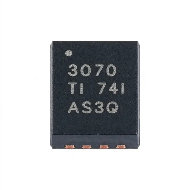
The Texas Instruments TPS63070RNMT is a high-efficiency, wide-input buck-boost DC-DC switching regulator that maintains a regulated output whether the input is above or below the target. It operates from 2V to 16V input, delivers up to 2A output current, and provides an adjustable output of 2.5V to 9V in a compact 15-pin VQFN-HR (RNM) package with -40C to +125C junction operation. A buck-boost converter is a type of DC-DC switching regulator within the broader power management IC category that combines buck (step-down) and boost (step-up) topologies. This lets a single inductor-based stage produce a stable rail from sources such as 4-cell alkaline, 12V lead-acid, or solar inputs whose voltage swings across the output level. The TPS63070 belongs to the switching voltage regulator family used in portable, industrial, and IoT power systems. Key features include a 3.6A switch current limit, 2.4MHz switching frequency, and low quiescent current of approximately 50uA typical. Synchronous rectification with integrated MOSFETs improves efficiency and reduces external component count, while the 2.4MHz clock permits small inductors and capacitors for a compact footprint. PWM mode maximizes heavy-load efficiency and PFM mode preserves light-load efficiency; the device also supports negative output current sinking in PWM mode per TI datasheet SLVSDD7B. Architecture-wise, the four-switch synchronous buck-boost topology seamlessly transitions between buck, buck-boost, and boost operating regions with a single inductor, avoiding output discontinuity when the battery voltage crosses the setpoint. The adjustable feedback (FB) pin sets the output with a resistor divider, and programmable soft-start limits inrush current. Typical applications include battery-powered portable instruments, industrial sensors, IoT wireless nodes, and 12V rail conditioning for microcontrollers, RF modules, and displays. Wide input tolerance makes it ideal for solar or vehicle-supplied systems. For best results, keep the inductor and input/output capacitor loops short, place the input capacitor at VIN and PGND, and provide adequate copper on the thermal pad. Pricing references are as of 2026-08-28.
TPS63710 - 1A Low Noise Inverting Buck Converter | TI
The Texas Instruments TPS63710 (TPS63710DRRR) is a low-noise synchronous inverting buck converter that generates a negative output voltage down to -5.5 V from a positive input of 3.1 V to 14 V, delivering up to 1 A of output current depending on the input-to-output voltage ratio. It is packaged in a 3-mm x 3-mm 12-pin WSON with exposed pad (12-WFDFN), providing excellent thermal performance for space-constrained designs. An inverting buck converter is a type of DC-DC switching regulator that produces a negative output rail from a positive supply. It belongs to the broader family of switching voltage regulators within power management ICs, which convert and regulate voltages efficiently using inductive energy storage rather than the dissipative approach of linear regulators. This makes inverting buck converters well suited to battery-powered and higher-current negative-rail applications where charge pumps cannot supply enough current. Key features of the TPS63710 include a filtered reference system with an external capacitor on the CAP pin that suppresses low-frequency 1/f noise up to approximately 100 kHz, a performance level required in high-performance telecommunication systems. The fixed-frequency PWM control topology gives predictable switching behavior and simple EMI filtering. Synchronous rectification eliminates the external Schottky diode, improving efficiency and reducing bill-of-material count. An enable pin supports power sequencing, and integrated soft-start limits inrush current. The device targets applications requiring a clean negative rail, such as op-amp supply rails, data converters, RF transceivers, bias supplies for GaN amplifiers, and optical modules. Its low-noise reference system makes it suitable for powering sensitive analog circuitry where output ripple and noise degrade signal integrity, while the wide input range supports both 5 V and 12 V system rails. When designing with the TPS63710, select input and output capacitors and an inductor with adequate saturation current to maintain stability and handle peak currents, and solder the exposed thermal pad to a copper area for heat dissipation. As of 2026-08-29, single-unit pricing from distributors starts near $1.51 (LCSC), with stock available at DigiKey, Mouser, and LCSC.
TPS63710DRRR - 1A Low-Noise Inverting Buck Converter | TI
The Texas Instruments TPS63710DRRR is a low-noise synchronous inverting buck converter that generates a negative output voltage down to -5.5 V from a positive input of 3.1 V to 14 V, delivering up to 1 A of load current depending on the input-to-output voltage ratio. It is housed in a 12-pin WSON package with an exposed thermal pad (12-WFDFN, 3 mm x 3 mm) that provides low thermal resistance for compact, high-density designs. An inverting buck converter is a type of DC-DC switching regulator that produces a negative output rail from a positive supply rail. It belongs to the broader family of switching voltage regulators within power management ICs, which convert and regulate voltages efficiently using inductive energy storage rather than the dissipative approach of linear regulators. This makes inverting buck converters well suited to battery-powered and higher-current negative-rail applications where simple charge pumps cannot supply enough current and where LDO efficiency would be unacceptable. Key features of the TPS63710 include a filtered reference system with an external capacitor on the CAP pin that suppresses low-frequency 1/f noise up to approximately 100 kHz - a noise performance required in high-performance telecommunication systems. The fixed-frequency PWM control topology gives predictable switching behavior and simplifies EMI filtering. Synchronous rectification eliminates the need for an external Schottky diode, improving efficiency and reducing bill-of-material count. An enable pin supports power sequencing, and integrated soft-start limits inrush current at startup. The device targets applications requiring a clean negative rail such as op-amp supply rails, data converters, RF transceivers, bias supplies for GaN amplifiers, and optical modules. Its low-noise reference system makes it well suited to powering sensitive analog circuitry where output ripple and noise would otherwise degrade signal integrity, while the wide 3.1 V to 14 V input range supports both 5 V and 12 V system rails. When designing with the TPS63710, choose input and output capacitors plus an inductor with adequate saturation current to maintain stability and handle peak currents, and solder the exposed thermal pad to a copper area for heat dissipation. As of 2026-10-11, single-unit pricing from distributors starts near $1.51 (LCSC), with stock available at DigiKey, Mouser, and LCSC. This page synthesizes distributor pricing, drop-in alternatives, and practical design notes not found in the manufacturer datasheet.
TPS63900DSKR - 400mA 75nA IQ Buck-Boost DVS Converter | Texas Instruments
The Texas Instruments TPS63900DSKR is a four-switch synchronous buck-boost converter with 400 mA maximum output current, an ultra-low 75 nA quiescent current, and 32 user-programmable output voltage settings from 1.8 V to 5 V, housed in a 10-pin WSON (DSK) exposed-pad package. It accepts an input voltage range of 1.8 V to 5.5 V and integrates an adjustable input current limit plus Dynamic Voltage Scaling (DVS), which lets the host step the output between two preloaded voltages during operation. A buck-boost DC-DC converter is a switching regulator topology that maintains a regulated output voltage whether the input voltage sits above, below, or equal to the output. Unlike a buck (step-down only) or boost (step-up only) regulator, the buck-boost uses four switches to seamlessly transition between modes, eliminating output-voltage transients during the mode boundary. Within the power management hierarchy, the TPS63900 belongs to the broader family of switching regulators (DC-DC converters) that also includes LDOs, charge pumps, and PMICs. Its 75 nA quiescent current makes it a member of the nano-IQ class favored by battery-powered IoT designs. Key differentiating features include single-mode operation that avoids the mode-switching transients and unpredictable inductor current ripple seen in many competing buck-boost parts, 32 selectable output voltages stored in a one-time-programmable (OTP) memory, true shutdown with 5 nA Iq, and an exposed thermal pad that lowers junction-to-ambient thermal resistance. The DVS pin toggles between two programmed Vout levels without software reload delay, an advantage for systems that must reduce the rail during sleep. Architecturally, the TPS63900 uses a peak-current-mode control loop with synchronous rectification. A single 1-µH inductor handles all four switching phases, reducing BOM cost. The internal MOSFETs are rated for the full 1.8-5.5 V input range, and the adjustable input current limit lets designers protect weak source batteries such as coin cells or energy harvesters. Typical applications include battery-powered IoT nodes, wearables, energy-harvesting sensor platforms, BLE/Zigbee radio power rails, ultra-low-power MCUs, and backup-power systems where the converter must hold regulation across a wide Vin swing. The combination of nano-Iq, DVS, and OTP-programmable outputs is especially well suited to designs that spend most of their life in standby and burst-transmit at higher loads. When designing with this part, follow the datasheet's recommended 1 µH inductor with low DCR (< 50 mΩ) and place the four ceramic bypass capacitors (2x 10 µF input + 2x 10 µF output minimum) within 2 mm of the package. Check the worst-case thermals at the maximum 400 mA load, since the WSON-10 package relies on PCB copper for heat spreading. This page synthesizes XAIPART distributor pricing, drop-in alternatives sourced from TI cross-reference data and same-family parametric memory, and practical design notes that go beyond the manufacturer datasheet to accelerate your selection.

TPS65951A1ZWSR - OMAP PMIC + Audio Codec 169-NFBGA | Texas Instruments
The Texas Instruments TPS65951A1ZWSR is an integrated power management IC (PMIC) designed for mobile cellular handsets powered by Li-ion, Li-ion polymer, or cobalt-nickel-manganese battery cells. It connects to an application processor and/or modem and is specifically optimized to meet the power requirements of Texas Instruments OMAP processor devices. The device is supplied in a 169-ball NFBGA (LFBGA) package measuring 12x12 mm. A power management IC (PMIC) is a specialized class of power management integrated circuits that combines multiple voltage regulators, sequencing logic, and supervisory functions on a single die, reducing board area and BOM count in battery-powered systems. Within this hierarchy, the TPS65951 sits at the system-power level, sitting above individual DC-DC converters and LDO regulators and integrating the entire handheld power tree. According to the TI data manual, the TPS65951 contains several buck converters and low-dropout regulators to generate the multiple rails required by application processors, plus USB transceiver and charger interface functionality typical of the TPS659xx handset family. A distinctive feature is its complete audio subsystem: an entire audio module with audio codecs, digital filters, input preamplifiers and amplifiers, and class-D output amplifiers, allowing a single chip to manage both power and audio signal chains. Typical applications include OMAP-based smartphone and tablet power management, handheld/mobile device power sequencing, and communication control in cellular handsets. The industrial temperature grade (per distributor data) supports embedded and portable instrumentation designs beyond handsets. When designing with the TPS65951A1ZWSR, follow the TI reference schematics for OMAP power sequencing, as rail ordering is controlled by the device's internal state machine. Verify software I2C configuration against the TI application code, and confirm battery charger parameters match the chosen Li-ion cell chemistry. Pricing and availability should be verified as of 2026-08-29.
TPS82085SILR - 3A Step-Down Converter Module | Texas Instruments
The Texas Instruments TPS82085SILR is a high-efficiency, 3A step-down converter module in a compact 8-pin MicroSiP package. It integrates a synchronous step-down converter and an inductor, simplifying design and reducing external components. The module operates from an input voltage range of 2.5V to 6V and provides an adjustable output voltage from 0.8V to 6V, making it suitable for a wide range of point-of-load (PoL) applications. A step-down converter module, also known as a buck converter module, is a power management IC that efficiently converts a higher input voltage to a lower output voltage. It integrates the switching regulator, inductor, and often compensation components into a single package, reducing PCB area and design complexity. This module is part of the broader category of DC-DC converters, which are essential in power management systems for converting and regulating voltages in electronic devices. Key features of the TPS82085SILR include a high efficiency of up to 95%, a switching frequency of 2.8MHz, and integrated soft-start to reduce inrush current. It also features enable (EN) and power-good (PG) pins for flexible power sequencing, over-temperature protection, and hiccup short-circuit protection. The MicroSiP package measures only 3.5mm x 3.5mm, enabling compact designs for space-constrained applications. The module uses a synchronous buck topology with integrated MOSFETs and a fixed-frequency PWM control. The integrated inductor is optimized for efficiency and low profile, and the module is designed for automated assembly with standard surface-mount equipment. The high switching frequency allows the use of small external capacitors, further reducing solution size. Typical applications include point-of-load regulation for FPGAs, DSPs, and ASICs, as well as power supplies for portable devices, industrial equipment, and networking hardware. The wide input range and adjustable output make it versatile for various voltage rails. When designing with the TPS82085SILR, ensure proper input and output capacitor selection as per the datasheet recommendations. The EN pin can be used for sequencing, and the PG pin provides a status signal for monitoring. Thermal performance is enhanced by the exposed pad, which should be connected to a large copper area for heat dissipation.
TPS82130SILR - 17V 3A Step-Down MicroSiP Module | Texas Instruments
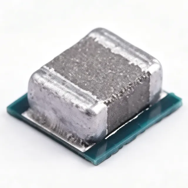
The Texas Instruments TPS82130SILR is a 17V-input, 3A step-down converter MicroSiP power module integrating a synchronous buck converter and inductor into an 8-pin uSIP (SIL) package measuring 3.0mm x 2.8mm x 1.5mm. It accepts 3V to 17V input and delivers up to 3A continuous output current with an adjustable output from 0.9V to 5V, achieving typical efficiency above 90% at moderate loads. A step-down converter, also called a buck converter, is a switching DC-DC voltage regulator that converts a higher input voltage to a lower output voltage with high efficiency. Buck converters form a core building block of power management IC hierarchies, sitting alongside LDOs, charge pumps, and power modules. The TPS82130 further collapses discrete switching FETs, inductor, and loop compensation into a single micro module, dramatically reducing external component count and PCB area compared to discrete regulator designs that require external FETs, a power inductor, and compensation components. Key features include the wide 3V-17V input range that supports 12V and 5V bus systems, 3A continuous output, adjustable 0.9V-5V output via external resistor divider, 2.2MHz fixed switching frequency that allows small external capacitors, internal soft-start for inrush current limiting, a power-good output flag for sequencing, an enable pin for shutdown control, and thermal shutdown protection. The MicroSiP package exposes a bottom thermal pad that routes heat directly into the PCB copper pour. Technically, the TPS82130 uses fixed-frequency peak-current-mode control, providing fast transient response and stability with minimal output capacitance (typically 22uF ceramic). It supports 100% duty cycle operation for low dropout at high VIN-to-VOUT ratios. The integrated shielded inductor reduces radiated EMI while simplifying PCB layout, and the low 1.5mm profile suits automated assembly with standard surface-mount equipment. Typical applications include point-of-load (POL) power for FPGAs, DSPs, and ASICs in industrial systems, factory automation sensor supplies, 12V-rail distributed power in IoT edge nodes, and portable test equipment where small solution size is critical. When designing, follow the datasheet recommendations for input and output ceramic capacitance, place the module close to the load, and provide a generous copper area under the thermal pad, especially at high output currents. Pricing references apply as of 2026-08-28. This page synthesizes distributor pricing, drop-in alternatives, and practical design notes not found in the manufacturer datasheet.
TPS82140SILR - 17V 2A Step-Down MicroSiP Module | Texas Instruments
The Texas Instruments TPS82140SILR is a 17V input, 2A continuous output synchronous step-down converter MicroSiP power module with integrated inductor, packaged in a compact 3.0 mm x 2.8 mm x 1.5 mm uSIP (SIL) 8-pin module. The device delivers an adjustable output of 0.9V to 6V from a 3V to 17V input rail and achieves up to 2A continuous load current. It uses DCS-Control topology with a 2 MHz nominal switching frequency and Power Save Mode for light-load efficiency, drawing only 20 uA quiescent current. A step-down (buck) converter is a switch-mode power supply topology that efficiently steps a higher DC input voltage down to a lower DC output voltage by rapidly switching an inductor and rectifying the stored energy. The TPS82140 integrates the synchronous power stage, the shielded inductor, and the compensation network into one MicroSiP package, eliminating external magnetics design and shrinking PCB area by roughly 60% compared to discrete buck implementations. As part of the broader power-management IC hierarchy, it sits between discrete switching regulators and fully discrete buck converters. Key specifications include 2A continuous output current, 0.9V to 6V adjustable output voltage, 3V to 17V input voltage range, 17V maximum input, 2 MHz typical switching frequency, 20 uA quiescent current, and 1% feedback voltage accuracy. The TPS82140 operates from -40C to +125C junction temperature and includes internal soft-start, thermal shutdown, and a power-good indicator. The integrated inductor shields against radiated EMI and removes the need for a separate inductor selection. Typical applications include industrial 12V and 24V bus point-of-load rails, portable and battery-powered equipment, communication infrastructure modules, factory automation nodes, and space-constrained consumer devices. The wide 17V input rating makes it especially suitable for industrial sensors and 12V supply rails. When designing with this device, follow the manufacturer recommended input and output capacitor values and keep the input capacitor loop area minimal. The MicroSiP package dissipates heat primarily through the PCB copper pads; ensure adequate copper area on top and inner layers for thermal relief. This page synthesizes distributor pricing, drop-in pin-compatible alternatives, design notes, and application guidance not found in the TI datasheet alone.
TPS826711 - 600mA 1.8V MicroSiP Buck Module | Texas Instruments
The Texas Instruments TPS826711 is a fully integrated, low-noise step-down DC-DC converter module in a MicroSiP package, delivering up to 600mA output current. It operates from a 2.3V to 4.8V input and provides a fixed 1.8V output. The module integrates the switching regulator, inductor, and input/output capacitors, requiring no additional external components for a complete power supply solution. This high level of integration minimizes board space and simplifies design, making it ideal for space-constrained portable applications. A step-down converter, also known as a buck converter, is a type of DC-DC converter that steps down an input voltage to a lower output voltage while maintaining high efficiency. It is a fundamental building block in power management, converting a higher voltage rail to a lower one for powering digital ICs, sensors, and other loads. The TPS826711 belongs to the family of switching regulators, which are more efficient than linear regulators for large voltage differences, making them essential in battery-powered devices where power conservation is critical. Key features include a regulated 5.5MHz switching frequency, which allows tiny external components and reduces output ripple. It achieves up to 90% efficiency, minimizing power loss and extending battery life. The device also features a low quiescent current of 17uA, making it suitable for always-on applications. Additionally, it includes spread-spectrum PWM frequency dithering to reduce electromagnetic interference (EMI), a critical feature for noise-sensitive systems. Technically, the TPS826711 is based on a high-frequency synchronous step-down topology, using both high-side and low-side MOSFETs to achieve high efficiency. The integrated inductor and capacitors are co-packaged in the MicroSiP, ensuring predictable performance and reducing parasitic effects. The device operates in power-save mode at light loads, further improving efficiency across the entire load range. Typical applications include powering microcontrollers, DSPs, and other digital ICs in battery-powered devices such as wearables, IoT sensors, and portable medical equipment. Its low noise and high efficiency also make it suitable for RF transceivers and audio codecs where clean power is essential. When designing with the TPS826711, ensure adequate input and output decoupling as recommended in the datasheet. The power-save mode provides excellent light-load efficiency but may introduce output ripple; consider this trade-off in noise-sensitive applications.
TPS84250RKG - 7-50V, 2.5A Step-Down Power Module | TI
The Texas Instruments TPS84250RKG is a 7 V to 50 V input, 2.5 A step-down integrated power solution that bundles a DC/DC converter, inductor, and passives into a 41-pin B0QFN (RKG) module. According to TI product page, it accepts a wide 7 V to 50 V input rail and delivers an adjustable output from 2.5 V to 15 V at up to 2.5 A of continuous load current with as few as five external components. A step-down integrated power solution, sometimes called a power module or PMIC with integrated magnetics, combines the switching FETs, output inductor, and key passives inside the package, eliminating the loop-compensation and magnetic-component selection normally required when designing a discrete buck regulator. The category sits within the broader DC-DC converter family, which itself belongs to power management ICs. By absorbing magnetics into the package, module families such as the TPS84xxx significantly reduce PCB area, simplify EMI containment, and accelerate time-to-prototype compared to a discrete buck. Key features of the TPS84250RKG include integrated MOSFETs and inductor, a switching frequency that supports small input/output capacitor count, internal soft-start with monotonic start-up into pre-biased loads, and protection features such as overcurrent, thermal shutdown, and UVLO with hysteresis. The device uses an internal feedback network so only one resistor is needed to set output voltage in the 2.5 V-15 V range, and the pinout supports standard QFN surface-mount mounting and testing. Typical applications include 24 V industrial bus rails, factory automation PLCs, building automation, 48 V telecom point-of-load conversion, test and measurement equipment, and any noise-sensitive distributed-power bus. The wide 7 V-50 V input allows direct connection to 12 V, 24 V, 36 V, and 48 V supplies without a pre-regulator. When designing with this device, follow TI's recommended PCB land pattern and thermal via array to keep junction temperature in spec under full-load operation. Estimate thermal performance using the datasheet theta-JA versus the user's copper area; inadequate copper or missing vias will cause thermal shutdown at 2.5 A under high VIN-VOUT conditions. Choose TPS84250RKG over a discrete buck where you need a proven, layout-compact solution in days rather than weeks.
TPSM13604H - 4A Step-Down Power Module | Texas Instruments
The Texas Instruments TPSM13604H is a SIMPLE SWITCHER power module that integrates a step-down DC-DC converter with an inductor and other passive components into a compact 7-TO-PMOD package. It accepts an input voltage from 5V to 36V and delivers an adjustable output voltage from 3V to 16V with up to 4A of continuous output current. The module is designed for easy implementation, requiring only three external resistors and four external capacitors to complete the power solution. A power module is a complete DC-DC converter solution that integrates the controller, power FETs, inductor, and often compensation circuitry into a single package. This integration simplifies PCB layout, reduces design time, and improves thermal performance compared to discrete solutions. The TPSM13604H belongs to the SIMPLE SWITCHER family, which is known for its ease of use and robust performance in industrial, automotive, and communications applications. Key features include a wide input voltage range of 5V to 36V, adjustable output voltage down to 3V, and a maximum output current of 4A. The module offers exceptional power conversion efficiency, line and load regulation, and output accuracy. It includes protection features such as thermal shutdown, input undervoltage lockout, output over-voltage protection, short-circuit protection, and output current limit. Additionally, it supports start-up into a pre-biased output and allows the switching frequency to be adjusted up to 700 kHz with a single resistor. The TPSM13604H uses an innovative package that enhances thermal performance and allows for hand or machine soldering. The 7-TO-PMOD package is designed for surface-mount assembly and provides excellent heat dissipation. The module operates over a junction temperature range of -40°C to +125°C, making it suitable for harsh environments. Typical applications include point-of-load (PoL) converters for FPGAs, ASICs, and microprocessors, as well as industrial control systems, test and measurement equipment, and automotive infotainment systems. The wide input range and high output current make it ideal for systems powered from 12V or 24V rails. When designing with the TPSM13604H, ensure proper input and output capacitance to maintain stability and minimize ripple. The adjustable output voltage is set by an external resistor divider, and the switching frequency can be programmed with a single resistor. Adequate thermal management is essential when operating at high output currents and high input-to-output voltage differentials.
TPSM265R1SILR - 65V Input 100mA Buck Power Module | Texas Instruments
The Texas Instruments TPSM265R1SILR is a 3V to 65V input, 100mA step-down DC-DC power module with an adjustable output voltage range of 1.233V to 15V, housed in a compact 2.8 mm x 3.7 mm uSIP module package. It integrates a synchronous buck controller, power MOSFETs, and the output inductor into a single easy-to-use device. A step-down power module is a complete DC-DC converter solution in one package. Unlike a discrete buck regulator design, a power module places the controller, switching FETs, inductor, and passives inside a single molded package, eliminating magnetics selection and layout optimization from the design cycle. Power modules sit at the top of the point-of-load (PoL) power hierarchy: voltage regulator -> switching regulator -> buck converter -> integrated power module, all within the broader power management IC (PMIC) category. Key differentiating features of the TPSM265R1SILR include an ultra-low quiescent current of 10.5 uA, which enables very high light-load efficiency in always-on and battery-backup systems; a maximum continuous input voltage of 65 V, providing robust headroom for industrial 24 V and 48 V nominal buses; and full integration of the power stage and inductor for a minimal external component count. Fixed 3.3 V and 5 V output options are also available in the same family. Technically, the module employs a synchronous step-down topology with integrated high-side and low-side MOSFETs and an internal output inductor. The wide 3V to 65V input range with an internal controller and protection features allows direct connection to industrial and automotive-style supply rails, reducing the need for a front-end transient suppressor stage in moderately protected systems. Ultra-low IQ supports low standby power in always-connected nodes. Typical applications include industrial programmable logic controller (PLC) I/O and sensor supply rails, 24V/48V auxiliary bias supplies for field transmitters and gate drivers, and building-automation or battery-powered monitoring nodes where 10.5 uA quiescent current extends battery life. The small 2.8 mm x 3.7 mm footprint also suits dense multi-rail boards. Design consideration: because the inductor is internal, verify the estimated thermal and output-current requirements stay within the 100 mA rating across your input voltage and ambient temperature range, and follow the TI datasheet layout guidelines for input capacitance placement. This page synthesizes distributor pricing, drop-in family alternatives, and practical design notes not found in the manufacturer datasheet.

TPSM33615FRDNR - 36V 1.5A Sync Buck Module | Texas Instruments
The Texas Instruments TPSM33615FRDNR is a 3-V to 36-V input, 1-V to 15-V output, 1.5-A synchronous buck power module integrated in a HotRod QFN-FCMOD (RDN) package with 11 pins. Headline parameters include 36-V maximum input voltage, 1.5-A continuous load current, and 88% typical efficiency, all delivered in a 3.5 mm x 4.5 mm surface-mount footprint. A buck converter (step-down switching regulator) is a switching-converter topology that reduces a higher DC input voltage to a lower regulated DC output voltage using an inductor, capacitor, and synchronous MOSFET switches. It sits within the broader power management IC hierarchy: buck converter -> DC-DC converter -> switching regulator -> power management IC. A power module such as the TPSM33615FRDNR integrates the controller, MOSFETs, inductor, and compensation network into one package, simplifying PCB layout and reducing design risk versus discrete buck implementations. Key features include 1.5-uA quiescent current, 1-MHz fixed switching frequency, programmable output voltage from 1 V to 15 V, and selectable PFM or FPWM light-load operation. The HotRod QFN-FCMOD package reduces parasitic inductance and improves thermal performance. Integrated protections include over-current, over-temperature, under-voltage lockout, automatic fault recovery, and 1% output voltage accuracy across load and line. The integrated inductor and shielding minimize radiated EMI, which is critical for industrial and instrumentation applications that must pass CISPR 25 or CISPR 32. Technically, the TPSM33615FRDNR uses a peak current-mode control topology with internal compensation, an external RT resistor to program switching frequency, and a MODE pin to select PFM (light-load efficiency) versus FPWM (constant-frequency low-noise) behavior. The HotRod flip-chip QFN package eliminates bond wires, reducing switching-node ringing and DC resistance losses. Typical applications include industrial 24-V rail point-of-load regulation, factory automation sensors, building automation controllers, low-noise bias supplies for analog front ends, and portable or battery-powered equipment operating from multi-cell lithium packs. The wide 3-V to 36-V input range supports 12-V and 24-V industrial buses directly. When designing with this device, keep the input capacitors close to VIN and PGND pins to minimize switching-node ringing, and connect the exposed thermal pad to a sufficient ground copper pour. Select PFM mode for highest light-load efficiency, or FPWM when low EMI is the top priority. This page synthesizes distributor pricing, drop-in alternatives, design notes, and application guidance not found in the manufacturer datasheet alone, giving engineers a single reference for component selection, PCB implementation, and sourcing decisions.
TPSM53604RDAR - 36V 4A Step-Down Power Module | TI
The Texas Instruments TPSM53604RDAR is a 36-V input, 4-A step-down DC/DC power module that integrates power MOSFETs, a shielded inductor, and passives in a thermally enhanced 15-pin Enhanced HotRod QFN package measuring 5.5 mm x 5 mm x 4 mm, delivering an adjustable 1 V to 7 V output from a 3.8 V to 36 V input. A power module is a highly integrated point-of-load (PoL) DC/DC converter: within the broader hierarchy of power management ICs, a step-down (buck) converter reduces a higher input voltage to a lower regulated output, and a power module goes one step further by co-packaging the controller or converter IC, switching MOSFETs, inductor, and key passives into a single surface-mount package. This integration eliminates inductor selection and magnetics design from the engineering workflow, dramatically reducing board area, bill-of-materials count, and design risk compared with a discrete buck converter solution. Key features of the TPSM53604 include its wide 3.8 V to 36 V input range, which directly supports 12-V, 24-V, and industrial 24 V nominal rails with transient headroom; an adjustable output spanning 1 V to 7 V; a continuous 4-A output current rating; and a fixed-frequency peak-current-mode control topology with optimized internal compensation. The Enhanced HotRod QFN construction places the die close to the package pins, minimizing parasitic inductance for low EMI and improved thermal performance. Technically, the module integrates a shielded inductor that produces low radiated electromagnetic emissions, simplifying CISPR-class EMI compliance work. The thermally enhanced package dissipates heat through the PCB, and the simple footprint with all pins on the perimeter makes layout and inspection straightforward. Shutdown quiescent operation and enable functionality support low standby power designs. Typical applications include industrial automation and PLC I/O modules, 12-V and 24-V distributed power systems, test and measurement instrumentation, telecom and networking equipment auxiliary rails, and embedded processor point-of-load supplies derived from wide-input industrial buses. Design consideration: at high input voltages and high output current, verify junction temperature using the datasheet thermal derating curves; adequate PCB copper area beneath the module is the primary thermal solution. This page synthesizes verified distributor data, same-family drop-in alternatives, and practical design guidance not found in the manufacturer datasheet alone. Pricing shown reflects distributor data as of 2026-10-19.
TPSM5601R5 - 60V In, 1.5A Step-Down Power Module | TI
The Texas Instruments TPSM5601R5 is a highly integrated 1.5-A step-down DC/DC power module combining a 60-V maximum input converter, power MOSFETs, a shielded inductor, and support passives in a thermally enhanced 5-mm x 5.5-mm x 4-mm 15-pin Enhanced HotRod QFN package. It delivers an adjustable output voltage of 1.0 V to 6 V from a 4.2-V to 60-V input range with a fixed 400-kHz switching frequency. A power module is a complete DC-DC converter solution that integrates the controller, switching MOSFETs, inductor, and compensation network into a single surface-mount package. Within the power management hierarchy (power module -> step-down converter -> DC-DC converter -> power management IC), modules eliminate magnetics selection and loop compensation design, reducing time-to-market and layout risk compared to discrete converter solutions. Key features include the wide 60-V input rating suited to 24-V and 48-V industrial rails with transient headroom, an output range of 1.0 V to 6 V set by a single external resistor divider, and as few as four external components for the complete solution. The Enhanced HotRod QFN construction places the die directly against the thermal pad, delivering low EMI, excellent thermal performance, and all pins accessible from the package perimeter for simple layout and inspection. The internal compensation and integrated shielded inductor provide stable operation across the load range while reducing solution height and BOM count. The device operates from a -40C to +125C junction temperature range, supporting industrial and automotive-adjacent environments. The TPSM5601R5S variant adds spread-spectrum operation for lower EMI peaks, and the TPSM5601R5H variant extends output capability up to 16 V. Typical applications include 24-V and 48-V industrial bus power supplies, factory automation and PLC I/O modules, test and measurement point-of-load rails, and distributed power systems that need a compact, regulated 1-V to 6-V rail from a wide input. Design tip: because the inductor is integrated, thermal design centers on the PCB copper pour under the thermal pad - provide at least a 1-square-inch ground plane with thermal vias for reliable operation at full 1.5-A load at elevated ambient temperatures.
TPSM81033VCDR - 2A 2.4MHz Synchronous Boost Module | TI
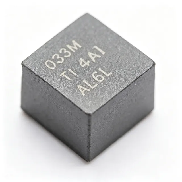
The Texas Instruments TPSM81033VCDR is a 5.5V, 2A synchronous boost power module using TI MagPack packaging technology, integrating a 0.43uH power inductor, power MOSFETs, and control circuitry into a 2.6mm x 2.5mm QFN-FCMOD (9) package. It accepts 1.8V to 5.5V input and delivers a 2.2V to 5.5V output with a 2A typical valley switching current limit. A boost converter (step-up switching regulator) is a DC-DC converter that raises an input voltage to a higher regulated output by storing energy in an inductor and releasing it at higher voltage through a switching FET. Boost converters form part of the power management IC hierarchy and are essential wherever battery voltage is lower than the load rail, such as single-cell Li-ion or alkaline systems needing a 5V rail. Key features include the integrated inductor enabled by MagPack technology, 2.4MHz switching frequency that allows tiny external components and fast transient response, fixed 5.0V output option by connecting FB to AVIN, selectable light-load mode (auto PFM or forced PWM) via the MODE pin, and power-good output. Protection features include 5.75V output overvoltage protection, output short-circuit protection, and thermal shutdown. The device uses adaptive constant on-time valley-current-control topology, providing fast load transients and predictable behavior. Forced PWM mode trades light-load efficiency for constant switching frequency, important for noise-sensitive RF and analog rails. Typical applications include smart devices and portable battery-powered equipment, RF power amplifiers needing a stable 5V from Li-ion cells, and OLED or display bias supplies. The tiny footprint and minimum external component count make it ideal for space-constrained wearables and IoT devices. Design consideration: boost converter output current capability decreases as input voltage drops; verify the 2A valley current limit supports your load at minimum VIN, and follow the datasheet PCB layout for thermal performance of the exposed package.
TPSM81033VCDR - 2A, 2.4MHz Boost Power Module | TI
The Texas Instruments TPSM81033VCDR is a 5.5V, 2A, 2.4MHz synchronous boost power module using MagPack packaging technology. It integrates a 0.43uH power inductor, power switches, and control circuitry into a compact 2.6mm x 2.5mm QFN-FCMOD (9) package, providing a nearly complete DC-DC boost converter solution with a minimum of external components. A power module is a type of DC-DC converter that integrates the power inductor and MOSFETs of a switching regulator into a single surface-mount package, sitting within the broader hierarchy of power management ICs that also includes LDOs, buck converters, and controllers. By integrating magnetics, modules dramatically reduce solution size and simplify layout compared to discrete converter designs. Key features include a 1.8V to 5.5V input voltage range, an adjustable 2.2V to 5.5V output voltage range (with fixed 5.0V output when FB is connected to AVIN), a 2A valley switching current limit, and integrated 0.43uH power inductor with excellent thermal performance. The device operates at 2.4MHz switching frequency using an adaptive constant on-time valley-current-control topology, enabling small external components and fast transient response. The module offers two light-load modes selected via the MODE pin: automatic PFM mode for highest efficiency and forced PWM mode for fixed-frequency noise immunity. Protection features include 5.75V output overvoltage protection, output short-circuit protection, and thermal shutdown. A power good output supports power-rail monitoring and sequencing. Typical applications include battery-powered smart devices, portable equipment, Li-ion cell to 5V conversion, and point-of-load boost rails in compact electronics where board space is constrained. The small 2.6mm x 2.5mm footprint suits wearables and handheld instrumentation. Design consideration: because the current limit is a valley limit of 2A typical, verify peak inductor current under worst-case load, minimum input voltage, and maximum output power to avoid hitting current limit during load transients.
TPSM81033VCDR - 5.5V 2A Boost Power Module | Texas Instruments
The Texas Instruments TPSM81033VCDR is a 5.5V, 2A synchronous boost power module with MagPack packaging technology, integrating a 0.43uH power inductor and power MOSFETs in a compact 2.6mm x 2.5mm QFN-FCMOD (9) package. It operates from a 1.8V to 5.5V input and delivers an adjustable 2.2V to 5.5V output, with a fixed 5.0V option by connecting FB to AVIN. A boost converter is a DC-DC switching regulator that steps an input voltage up to a higher output voltage. It is essential in battery-powered systems where cell voltage falls below the required rail. The TPSM81033 belongs to the power module family within power management ICs, integrating the magnetic component and power stage to reduce design effort and board space versus discrete solutions. Key features include a 2A valley switching current limit, fixed 2.4MHz switching frequency for small external components and low ripple, and an integrated 0.43uH inductor with excellent thermal performance. Adaptive constant on-time valley-current-control topology regulates the output, while two light-load modes (auto PFM and forced PWM) selected via the MODE pin balance efficiency and noise immunity. Optional spread spectrum frequency modulation minimizes EMI. The synchronous rectifier architecture eliminates the external Schottky diode, improving efficiency, and the integrated inductor reduces parasitic losses and radiated EMI. Only input and output capacitors plus feedback resistors are required. Protection features include 5.75V output overvoltage protection, output short-circuit protection, thermal shutdown, and a power good output for sequencing in multi-rail systems. Typical applications include smart devices and portable equipment powered by batteries, IoT sensor power supplies, and TFT-LCD bias or OLED display rails. The wide input range and high switching frequency suit space-constrained designs. Design tip: ensure adequate input and output capacitance for stability and low ripple, and use the MODE pin to trade efficiency against noise. For a fixed 5V output, tie FB to AVIN per the datasheet layout guidelines.
TPSM82813 - 3A 6V Step-Down Power Module | TI
The Texas Instruments TPSM82813 is a synchronous step-down DC/DC power module with integrated inductor, delivering up to 3A output current from a 2.75V to 6V input supply. Available in QFN and MagPack (SIL) packages, output voltage is adjustable from 0.6V to 5.5V via external resistors. A step-down (buck) converter is a DC/DC power converter that efficiently reduces a higher input voltage to a lower regulated output. Power modules integrate the inductor and control circuitry into a single package, sitting one level above discrete buck converters in the power management IC hierarchy and dramatically reducing design effort and PCB area compared to controller-plus-inductor solutions. Key features include optional frequency synchronization, adjustable soft-start, and output voltage tracking for power sequencing. The device also offers spread spectrum for EMI reduction, a power good output, adjustable UVLO, and light-load efficiency mode. Efficiency reaches approximately 95%, minimizing losses in high-current point-of-load designs. Technically, the TPSM82813 uses a fixed-frequency peak current-mode control topology, providing fast transient response and stable loop behavior. The integrated inductor is optimized for low loss and contained EMI, while the MagPack package improves thermal performance. Thermal behavior is characterized on a JEDEC 51-7 defined PCB. Typical applications include point-of-load converters for FPGAs, DSPs, and ASICs, plus power supplies for telecommunication, test and measurement, medical, and industrial sensor equipment. The wide 2.75V-6V input supports 5V and 3.3V bus conversions, and the small footprint enables dense rail designs. Design tip: follow datasheet input/output capacitance recommendations, configure soft-start and tracking for your power-up sequence, and use thermal vias under the module per the recommended land pattern. Pricing as of 2026-08-30, see tiers below.
TPSM82816 - 6A Step-Down Power Module 2.7-6V | TI
The Texas Instruments TPSM82816 is a 2.7V to 6V input, 6A output synchronous step-down DC/DC power module with an integrated inductor, packaged in the compact MicroSiP (SIE) package. It belongs to the TPSM8281x family of pin-to-pin 1A, 2A, 3A, 4A, and 6A compatible modules, delivering high power density and ease of use for point-of-load (PoL) power supplies. A step-down power module is a complete DC/DC converter solution that combines the switching regulator, power MOSFETs, and magnetic components in a single package. Unlike discrete regulators that require separate inductor selection and layout optimization, power modules simplify design, shrink solution size, and reduce EMI and efficiency risk. Power modules sit within the power management IC hierarchy, bridging discrete converters and fully integrated PMICs. Key features include an adjustable output voltage from 0.6V to 5.5V via a single resistor divider, optional frequency synchronization to an external clock, adjustable soft-start, and output voltage tracking for rail sequencing. Peak efficiency exceeds 90% for typical 5V-to-1.8V conversions, with the shielded integrated inductor improving EMI behavior. The device is based on a fixed-frequency peak current-mode control topology, which provides fast transient response and stable operation with ceramic output capacitors. The package integrates everything needed for a minimal-footprint POL supply, and protection features include overcurrent, overvoltage, and thermal shutdown. The switching frequency can be programmed to trade efficiency against solution size. Typical applications include POL power for FPGAs, ASICs, and processors in telecommunication, test and measurement, medical, and industrial systems, where TI cites high power density and ease of use as primary benefits. Because the family is pin-to-pin compatible, a single PCB layout supports current tiers from 1A to 6A, simplifying BOM scaling across product variants. When designing with the TPSM82816, provide adequate input and output ceramic capacitance for stability and transient response, and use the SS/TRACK pin to sequence multiple rails in multi-voltage systems.
TPSM82822A - 2A Step-Down Module, Integrated Inductor | TI
The Texas Instruments TPSM82822A is a 5.5-V input, 2-A synchronous step-down converter power module with an integrated inductor and forced PWM mode, housed in a compact 2 x 2.5 x 1.1 mm MicroSiP (uSiP) package. It delivers an adjustable output from 0.6 V to 4 V, simplifying point-of-load power design. A step-down converter, or buck converter, is a switching voltage regulator that efficiently reduces a higher DC input voltage to a lower regulated output. Within the power management IC hierarchy, the TPSM82822A is a power module: it integrates the buck converter IC, power MOSFETs, and the magnetic inductor into one surface-mount package, collapsing an entire DC-DC solution into about 5 mm2 of board area. Key features include a 2.4 V to 5.5 V input range, 2 A continuous output current, forced PWM operation for constant 2.2 MHz switching frequency and predictable EMI, power-good output, enable pin, and internal soft-start. Efficiency reaches approximately 95% at typical loads, and the high operating frequency allows small external capacitors and low output ripple. Technically, the module uses a synchronous buck architecture with integrated low-DS(on) MOSFETs and a proprietary control scheme. Integrating the inductor inside the package minimizes parasitic loop inductance, reduces radiated EMI, and enables automated assembly with standard surface-mount equipment per the TPSM8282x datasheet. Typical applications include powering FPGAs, DSPs, ASICs, and MCUs in industrial systems, optical modules, solid-state drives, and portable devices where board space is at a premium. Forced PWM keeps output ripple low and constant-frequency, suiting noise-sensitive analog and RF rails. Design consideration: follow the datasheet input/output capacitor recommendations exactly for stability, and provide adequate thermal copper area for sustained 2 A loads; the module does not eliminate thermal design entirely.
TPSM828303 - 3A Low-EMI Buck Module 2.25-5.5V | Texas Instruments
The Texas Instruments TPSM828303 is a 3A synchronous step-down DC/DC power module with integrated inductor, operating from a 2.25V to 5.5V input and providing an adjustable output from 0.5V to 4.5V in a compact QFN (RDS) or MagPack (PVC) package. A DC/DC power module is a complete point-of-load power supply that integrates the controller, power MOSFETs, inductor, and compensation into a single surface-mount package. As a member of the buck (step-down) converter family within the broader power management IC hierarchy, it efficiently reduces a higher input voltage to a lower output voltage while minimizing external component count, layout effort, and design risk compared to discrete converter solutions. Key features include the DCS-Control topology for fast load transient response with small output capacitance, 1% feedback voltage accuracy over the full operating range, and integrated EMI reduction technologies that ease radiated emissions compliance. Automatic PWM/PFM transition maximizes light-load efficiency, and enable, power good, output discharge, and overcurrent protection functions simplify system integration. The TPSM828303 is pin-to-pin compatible with the 1A (TPSM828301) and 2A (TPSM828302) family members, enabling current-rating scalability on one PCB layout. The integrated inductor with MagPack magnetic shielding (TPSM828303APVCBR variant) reduces radiated EMI and board area versus discrete designs. Operation over a -40C to +125C junction range suits industrial environments. Typical applications include point-of-load (POL) power for FPGAs, DSPs, and ASICs, optical module supplies, test and measurement equipment, and noise-sensitive portable designs where low EMI is mandatory. Design tip: follow the datasheet input/output capacitance recommendations - the DCS-Control topology supports output capacitors up to 200uF, and the EN pin plus power good signal enable proper rail sequencing in multi-rail systems. Prices as of 2026-08-30.