Motortreiber
Produkte (261)

L9977 - Automotive Dual H-Bridge Driver | STMicroelectronics
The L9977 is an automotive-grade dual H-bridge driver IC from STMicroelectronics, designed for controlling DC motors and inductive loads in automotive body applications. It integrates two full H-bridges capable of driving up to 5.5 A continuous current per channel, with a wide operating supply voltage range of 5.5 V to 36 V. The device is housed in a PowerSO-36 package, providing excellent thermal performance for high-current applications. An H-bridge motor driver is a power management IC that allows bidirectional control of a DC motor by selectively switching four transistors in an 'H' configuration. It is a fundamental building block in automotive electronics, enabling functions such as window lift, seat adjustment, and mirror positioning. The L9977 belongs to the family of motor drivers, which are part of the broader power management IC category, and it is specifically optimized for the harsh automotive environment. Key features of the L9977 include a low quiescent current of 50 µA in standby mode, making it suitable for always-on automotive modules. It offers overcurrent, overtemperature, and short-circuit protection, ensuring robust operation in fault conditions. The device also features a serial peripheral interface (SPI) for advanced diagnostics and control, allowing the microcontroller to monitor and configure the driver in real time. The PowerSO-36 package with exposed pad ensures efficient heat dissipation, enabling continuous operation at high currents. From a technical perspective, the L9977 utilizes a smart power technology that integrates logic, protection, and power stages on a single die. This reduces external component count and improves reliability. The SPI interface supports daisy-chaining of multiple devices, simplifying PCB layout in multi-motor systems. The device is AEC-Q100 qualified, meeting the stringent quality and reliability standards required for automotive applications. Typical applications include automotive body control modules, power window lift systems, seat position adjustment, and mirror folding. The L9977's ability to handle high currents and its robust protection features make it ideal for driving DC motors in these systems. Additionally, its low standby current is critical for battery-powered vehicles to minimize parasitic drain. When designing with the L9977, ensure proper PCB layout with adequate copper area for thermal management, especially when driving high currents continuously. The SPI interface should be configured correctly to enable fault reporting and diagnostic functions. Also, consider adding external flyback diodes or using the integrated freewheeling diodes to protect against inductive load transients.

L9977-TR - Dual Half Bridge Driver, 1.2A, 7-16.5V | STMicroelectronics
The L9977-TR is a monolithic integrated dual half bridge driver from STMicroelectronics, designed in BCD technology to drive various loads including DC motors. It is optimized for automotive electronics environmental conditions, delivering robust performance in harsh operating environments. The device provides two half-bridge outputs with a typical ON-resistance of 0.7 ohm and an output current capability of ±1.2 A, operating from a supply voltage range of 7 V to 16.5 V. The L9977-TR is available in a 20-pin SOIC (SO-20) package, suitable for surface-mount assembly. A dual half bridge driver is a power management IC that contains two independent half-bridge output stages, each capable of sourcing and sinking current to drive inductive or resistive loads such as DC motors, solenoids, and relays. In the system hierarchy, a dual half bridge driver falls under motor drivers, which are a subset of power management ICs, ultimately part of the broader semiconductor category. This component type is essential in automotive body control modules, where it controls actuators like window lifts, mirror adjustments, and seat positioning. Key features of the L9977-TR include half-bridge outputs with typical RON of 0.7 ohm, output current capability of ±1.2 A, operating supply voltage from 7 V to 16.5 V, and supply overvoltage protection for VVS up to 40 V. The device also features very low quiescent current, making it suitable for always-on automotive applications. The BCD (Bipolar-CMOS-DMOS) technology combines the advantages of bipolar, CMOS, and DMOS processes, enabling high-voltage capability, low power consumption, and high current drive in a single monolithic IC. The L9977-TR is designed for automotive electronics, withstanding the demanding environmental conditions such as wide temperature ranges, supply transients, and electromagnetic interference. The overvoltage protection up to 40 V ensures the device can survive load dump and other supply transients common in automotive power systems. The low ON-resistance minimizes power dissipation, improving thermal performance and system efficiency. Typical applications include automotive body control modules, DC motor drivers for window lifts and mirror adjustment, and relay drivers. The device's ability to drive inductive loads makes it suitable for solenoid and actuator control. In a typical automotive body control module, the L9977-TR interfaces directly with a microcontroller, receiving logic-level control signals and driving the load with the required current and voltage. When designing with the L9977-TR, ensure adequate PCB copper area for thermal dissipation, especially when driving loads near the maximum current rating. The supply voltage must be decoupled with a capacitor close to the VCC pin to handle transient currents. The logic inputs are compatible with 5V microcontrollers, but verify the input thresholds against the specific microcontroller's output levels.

L9979-TR - Automotive Dual H-Bridge Driver | STMicroelectronics
The L9979-TR is an automotive-grade dual H-bridge driver IC from STMicroelectronics, designed for controlling DC motors and inductive loads in 12V automotive systems. It integrates two independent H-bridge outputs capable of driving continuous currents up to 1.2A per channel, with a peak current capability of 2A. The device operates from a supply voltage range of 5.5V to 36V, making it suitable for a wide range of automotive power rails. It is available in a PowerSO-20 package, which provides excellent thermal performance for high-current applications. A dual H-bridge driver is a power management IC that contains two full H-bridge circuits, each capable of driving a DC motor bidirectionally or controlling two separate loads. It is a type of motor driver, which falls under the broader category of power management ICs. The L9979-TR integrates the power stage, control logic, and protection features, simplifying the design of motor control systems in vehicles. Key features of the L9979-TR include a low quiescent current of 10 µA in standby mode, which is critical for battery-powered automotive applications. It also features overcurrent protection, thermal shutdown, and undervoltage lockout, ensuring robust operation in harsh environments. The device is AEC-Q100 qualified, meeting the stringent reliability requirements of the automotive industry. Its SPI interface allows for advanced diagnostics and control, enabling real-time monitoring of load conditions and fault status. The L9979-TR uses a standard CMOS process technology, which balances performance and cost. The integrated protection features reduce the need for external components, saving board space and improving system reliability. The device's ability to operate at high temperatures (up to 150°C junction) makes it suitable for under-hood applications where ambient temperatures can be extreme. Typical applications include automotive HVAC actuators, mirror adjustment, seat positioning, and other DC motor control functions. The L9979-TR's dual H-bridge configuration allows it to control two motors independently, making it ideal for applications requiring multiple actuators. Its SPI interface enables precise control and diagnostics, which is essential for advanced automotive systems. When designing with the L9979-TR, it is important to ensure proper PCB layout to minimize parasitic inductance and resistance in the power path. Adequate decoupling capacitors should be placed close to the supply pins to handle transient currents. The thermal pad should be connected to a large copper area to dissipate heat effectively, especially when driving high currents continuously.

L99ASC03TR - 3-Phase BLDC Motor Pre-Driver | STMicroelectronics
The STMicroelectronics L99ASC03TR is a multifunctional system IC designed for three-phase brushless DC (BLDC) motor control applications, primarily targeting automotive systems. It integrates a flexible gate driver unit (GDU), a 5V low-dropout voltage regulator (LDO) capable of delivering up to 200 mA, and a 3.3V/5V reference voltage, all in a 48-pin LQFP-EP (7x7) package. The device operates from a wide input voltage range of 5.5V to 28V, making it suitable for both 12V and 24V automotive electrical systems. A brushless DC (BLDC) motor pre-driver is a specialized motor control IC that sits between a microcontroller (MCU) and the external power stage (MOSFETs or IGBTs). It translates low-voltage logic-level signals from the MCU into high-current gate drive signals that control the commutation and speed of a BLDC motor. In the system hierarchy, a BLDC motor pre-driver is a type of motor driver IC, which falls under power management ICs, ultimately part of the broader semiconductor category. The L99ASC03TR integrates the gate driver, voltage regulation, and protection features, reducing external component count and simplifying PCB design. Key features include a wide operating voltage range from 5.5V to 28V, a programmable gate drive current for optimized switching performance, and a built-in 5V LDO with 200 mA output capability. The device also provides a 3.3V/5V reference voltage with ±1% accuracy, SPI interface for configuration and diagnostics, and comprehensive protection features such as overcurrent, overvoltage, undervoltage, and thermal shutdown. These features ensure robust operation in harsh automotive environments. The L99ASC03TR employs a flexible architecture that supports both sensored and sensorless BLDC motor control. The gate driver unit can be configured for different external MOSFET/IGBT combinations, and the SPI interface allows real-time adjustment of gate drive strength and protection thresholds. The integrated LDO and reference voltage eliminate the need for separate power management components, reducing system cost and board space. Typical applications include automotive engine cooling fans, oil pumps, water pumps, HVAC blowers, and industrial BLDC motor drives. The wide input voltage range and automotive-grade robustness make it suitable for 12V and 24V systems. The device is AEC-Q100 qualified, ensuring reliability for automotive use. When designing with the L99ASC03TR, ensure proper PCB layout with adequate copper area for thermal dissipation, and place decoupling capacitors close to the VCC and LDO output pins. The SPI interface should be configured correctly to set the desired gate drive current and protection thresholds for the specific motor application.
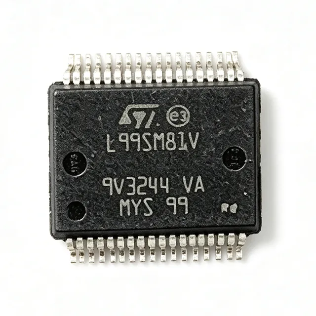
L99SM81V - Automotive Stepper Motor Driver | STMicroelectronics
The L99SM81V is an automotive-grade integrated driver for bipolar two-phase stepper motors, designed by STMicroelectronics for precise current-controlled micro-stepping with programmable amplitude. It integrates a microstepping controller with a power stage capable of driving up to 1.2 A per phase, and operates from a supply voltage range of 6 V to 28 V, making it suitable for direct connection to automotive battery rails. The device is available in a 40-pin QFN (6x6 mm) package and is AEC-Q100 qualified for automotive applications. A stepper motor driver is a power management IC that converts digital step and direction commands into the precise current sequences needed to rotate a stepper motor in controlled increments. It sits between a microcontroller and the motor, translating low-power logic signals into high-current drive signals. In the system hierarchy, a stepper motor driver is a type of motor driver, which falls under power management ICs, which are part of the broader category of analog and mixed-signal semiconductors. Key features of the L99SM81V include a programmable microstepping resolution up to 1/16 step, integrated current sensing with no external sense resistors, and a SPI interface for configuration and diagnostics. It also features overcurrent, overtemperature, and undervoltage protection, along with a low quiescent current in standby mode, which is critical for automotive battery conservation. The device is AEC-Q100 qualified, ensuring reliability across the -40°C to +150°C junction temperature range. The L99SM81V uses a proprietary current-control architecture that combines a constant-current chopper with a programmable decay mode, enabling smooth and quiet motor operation. The integrated current sensing eliminates the need for external sense resistors, reducing BOM cost and PCB area. The SPI interface allows real-time monitoring of fault conditions and precise adjustment of motor parameters, making it a flexible solution for complex automotive motion control. Typical applications include headlamp leveling systems, where precise positioning is required for optimal beam alignment, HVAC flap control for cabin comfort, and instrument cluster stepper motors for gauge indication. The wide supply voltage range and robust protection features make it ideal for direct battery connection in 12 V automotive systems. When designing with the L99SM81V, ensure adequate PCB copper area for thermal dissipation, especially when driving high currents continuously. The SPI interface should be isolated from high-current traces to minimize noise coupling. Proper decoupling capacitors on the supply pins are essential to maintain stable operation during motor transients.

LMD18200T/NOPB - 3A 55V H-Bridge Motor Driver | Texas Instruments
The Texas Instruments LMD18200T/NOPB is a 3A continuous (6A peak) H-bridge motor driver IC designed for motion control applications, housed in an 11-pin TO-220 power package. Key headline specifications are 3A continuous output current, 55V absolute maximum supply voltage, and integrated DMOS power devices on a multi-technology Bi-CMOS/DMOS monolithic structure. An H-bridge motor driver is a four-switch power stage that allows a DC motor or stepper winding to be driven in both directions from a single supply rail. The H-bridge sits within the broader hierarchy of motor driver ICs -> motion controllers -> power management ICs -> semiconductor ICs, and is a foundational building block for brushed DC and bipolar stepper motion systems. By integrating both the high-side and low-side switches, plus direction and PWM control logic, an H-bridge IC eliminates the discrete MOSFET design effort for sub-50V applications. Key features of the LMD18200T/NOPB include continuous 3A output current with 6A peak capability, a wide 12V to 55V supply range, built-in shoot-through protection, thermal shutdown, and a low-loss current-sense output that eliminates the need for a discrete sense resistor. The Bi-CMOS/DMOS process combines bipolar/CMOS logic with DMOS power transistors on a single die, achieving typical R_DS(on) values in the sub-0.3-ohm per switch region. The TO-220-11 package provides a thermally efficient through-hole footprint with formed leads optimized for vertical mount with an external heatsink. The device accepts TTL/CMOS-compatible DIRECTION and PWM inputs and integrates anti-shoot-through dead-time control, so external microcontroller logic is sufficient for full bidirectional speed and position control. Internal charge-pump-driven high-side switches allow 100% duty-cycle operation - critical for accurate low-speed DC motor control where PWM-frequency ripple cannot be tolerated on the output stage. Typical applications include brushed DC servo motor drives, bipolar stepper motor amplifiers (one LMD18200 per winding), robotic actuator drivers, valve and solenoid controllers, and industrial automation motion subsystems. The device is well suited to industrial 24V and 36V bus systems where its 55V rating provides sufficient transient margin. When designing with the LMD18200T/NOPB, plan for an external heatsink sized for continuous worst-case dissipation: at 3A and a 24V supply, internal conduction losses alone can exceed 4W. Place a 1uF or larger bulk decoupling capacitor close to the supply pins and add a 0.1uF ceramic high-frequency bypass to suppress the charge-pump switching noise that otherwise couples back to the motor terminals. This page synthesizes distributor pricing, drop-in alternatives, and practical design notes for the LMD18200T/NOPB that are not present in the manufacturer datasheet alone, and that are tailored to help engineers select, source, and qualify the part quickly.

LV8860V-TLM-H - Single-Phase Full-Wave Fan Motor Driver | onsemi
The onsemi LV8860V-TLM-H is a single-phase full-wave driver for brushless DC fan motors, integrating a Bi-CMOS control stage with parallel PWM speed command input in a 16-pin SSOP package. The device supports a wide supply range, including 24 V operation, and uses Silent PWM drive to reduce reactive current and radiated EMI in fan applications. Speed is commanded through a PWM input and a built-in closed-loop architecture holds RPM stable against supply and load variation. A fan motor driver (also called a single-phase BLDC fan driver or single-phase full-wave driver) is a power-management IC that commutates a two-coil brushless DC motor by alternately switching two half-bridges in synchronization with the rotor position, typically detected via a back-EMF sensing network. Fan drivers sit hierarchically under motor drivers, which belong to the broader power management and motion control IC category. Compared to discrete MOSFET bridges driven by a microcontroller, integrated fan drivers reduce BOM count, PCB area, and acoustic noise while providing built-in protection features such as thermal shutdown, current limiting, and lock rotor detection. Key features include Silent PWM drive for reduced audible switching noise, full-wave commutation for low torque ripple, lock detection with auto-restart, soft-start functionality, and integrated thermal shutdown. The 16-pin SSOP (LSSOP) package provides a compact footprint suitable for fan-embedded PCBs. The device accepts a wide supply range up to the 24 V fan bus and supports speed control via an external PWM signal, making it compatible with standard 4-wire PWM fan command interfaces used in PC, server, and industrial cooling subsystems. The LV8860V uses a Bi-CMOS process that combines bipolar output drive strength for the power H-bridge with low-power CMOS logic for control. Full-wave commutation with Silent PWM minimizes switching losses and reduces the high-frequency acoustic content that fans couple into chassis. Built-in lock detection rotates the rotor through a forced-commutation pattern during a stall event and automatically restarts when rotation recovers, eliminating the need for an external supervisory timer. Typical applications include CPU cooling fans, server and workstation blowers, industrial inverter fans, and 24 V office-automation equipment. The wide supply range and Silent PWM drive make it well suited for applications where acoustic noise and EMI compliance are critical design constraints. When designing with this device, ensure adequate copper area under the exposed pad for thermal relief, follow the recommended input bulk capacitance to absorb the reactive return current, and verify that the lock-detection timing matches the rotor inertia of the specific fan you are pairing with this driver. This page synthesizes distributor pricing, drop-in alternatives, and practical design notes for cooling-fan designers, providing information not consolidated in the manufacturer datasheet alone.

MC33486ADHR2 - Dual 15mOhm High-Side Switch H-Bridge Driver | NXP
The NXP Semiconductors MC33486ADHR2 is a self-protected dual 15 mOhm high-side switch that incorporates dual low-side switch control and protection features, housed in a 20-pin HSOP (HSSOP) surface-mount power package. Designed for H-bridge DC motor control applications, it integrates two high-side MOSFET outputs with on-state resistance of 15 mOhm typical each, supports supply voltages from 8 V to 28 V, and delivers continuous output current up to 10 A per channel. The device includes comprehensive on-chip protection: over-current shutdown, over-voltage clamp, thermal protection, and reverse-battery protection, enabling robust operation in harsh automotive and industrial environments. A high-side switch is a power-distribution semiconductor that connects a load to the positive supply rail when activated. The MC33486ADHR2 belongs to the high-side switch family within the broader power MOSFET driver hierarchy (power switch IC -> motor driver -> power management IC). Two channels combined with low-side control logic enable a full H-bridge topology for bidirectional DC motor control, replacing discrete MOSFETs plus driver ICs with a single integrated solution. This integration shrinks PCB area, reduces BOM count, and improves reliability by co-locating the protection circuitry with the switching elements. Key features include very low 15 mOhm typical on-resistance per channel minimizing conduction losses, integrated charge pump for full enhancement of the high-side N-channel MOSFETs at low supply voltages, PWM capability up to 1 kHz for variable motor speed, diagnostic output flag, and AEC-Q100 automotive qualification supporting automotive temperature grade -40C to +125C. The 20-pin HSOP package exposes the die pad for direct thermal conduction to the PCB copper, enabling sustained 10 A operation with proper board layout. The architecture combines two charge-pump-driven high-side MOSFETs with control logic, current sensing, and fault management. Internal charge pumps maintain VGS enhancement across the full supply range, ensuring low RDS(on) even at 8 V input. Cycle-by-cycle current limiting and thermal shutdown protect against short circuits and overload conditions, while an open-drain status flag reports fault conditions to the host microcontroller. Typical applications include automotive DC motor control (window lift, sunroof, seat adjustment, door lock, wiper), industrial brush DC motor drivers, solenoid drivers, and bidirectional DC load switching. The dual high-side topology is particularly suited to H-bridge configurations when paired with an N-channel low-side driver. When designing with this part, ensure the PCB copper area under the exposed pad is sufficient to dissipate the I^2R losses at 10 A continuous (approximately 1.5 W per channel at full load). Use wide copper pours and thermal vias to the inner power plane. Place the bootstrap/charge-pump capacitors as close as possible to the CP and VCC pins to minimize switching transients. This page synthesizes NXP datasheet specifications, parametric comparison against same-family NXP high-side switches, and practical PCB thermal design guidance not consolidated in the manufacturer PDF.

MC33689DDWBR2 - SPI SBC with LIN Transceiver, 32-SOIC | NXP
The NXP MC33689DDWBR2 is an SPI-controlled System Basis Chip (SBC) with integrated 5.0 V low-dropout regulator and LIN transceiver, housed in a 32-pin wide-body SOIC package (DW suffix). It combines many functions frequently used in an MCU-based automotive node plus a Local Interconnect Network (LIN) transceiver, operating from a 5.5 V to 18 V supply. A System Basis Chip (SBC) is a mixed-signal IC that integrates a voltage regulator, communication transceiver, and housekeeping functions (watchdog, reset, fail-safe) into a single package. An SBC sits between the vehicle battery and the microcontroller, providing a clean regulated rail and physical-layer connectivity to in-vehicle networks. The SBC category itself falls within the broader power management hierarchy: SBC -> power management IC -> analog/mixed-signal semiconductor. Key features include a 5.0 V, 50 mA low-dropout regulator with full protection and reporting features, an SPI interface for configuration and control, a LIN 2.0/2.1 physical-layer transceiver, and integrated fault handling. The 32-SOIC (7.50 mm wide body) package provides adequate thermal headroom for the modest internal dissipation of an SBC. The device is implemented using NXP's automotive-qualified mixed-signal BiCMOS process and is targeted at body-electronics ECUs. Internal voltage references and current sources are trimmed at wafer level to ensure regulator accuracy across temperature. The integrated LIN transceiver meets the LIN 2.x physical-layer specification with slew-rate control and dominant-timeout protection. Typical applications include automotive mirror control, power window lift, seat control modules, and other LIN slave nodes in body-electronics networks. Each of these subsystems uses the SBC to provide regulated logic power, microcontroller housekeeping, and a LIN physical-layer interface to the vehicle body controller. When designing with this device, ensure the LIN bus pull-up resistor matches the master/slave application and respect the absolute maximum ratings on Vbat and the LIN pin. Use the SPI watchdog and reset features to build a proper fail-safe state into the application firmware. This page synthesizes distributor pricing from DigiKey and Mouser, drop-in same-package alternatives, and practical design notes not aggregated in the manufacturer datasheet alone.

MC33816AE - Programmable Solenoid Controller Gate Driver | NXP
The NXP MC33816AE is a SMARTMOS programmable gate-driver IC for precision solenoid control applications, integrating five external MOSFET high-side predrivers and seven external MOSFET low-side predrivers in a 64-pin LQFP (10x10 mm) package. It targets high-current hydraulic and gasoline direct-injection solenoid drive, providing microcore-managed gate drive, diagnosis, and protection across four independent microcores and two SPI-configurable control blocks. A solenoid controller IC (also called an SD6 programmable solenoid driver) is a specialized power-management device that sits between an ECU/microprocessor and the external N-channel MOSFETs that actually switch current through fuel-rail or transmission solenoids. In the broader taxonomy, the MC33816AE is a gate driver -> power management IC -> semiconductor. It combines a charge-pump boost supply for high-side gate drive, built-in bootstrap diodes and half-bridge structures, current-sense amplifiers, and configurable peak-and-hold solenoid current profiles, so it replaces what would otherwise require an FPGA, op-amps, and discrete drivers. Key features include charge-pump boost, integrated bootstrap diodes for the high-side stages, configurable peak-and-hold solenoid current profiles, eight configurable pre-drivers (5 HS + 7 LS), SPI communication for ECU command and diagnostic telemetry, and built-in overcurrent/short-to-battery/short-to-ground protection. The device supports Vsupply of up to 72 V transient with steady-state operation to 36 V on the battery rail, and operates over the -40 C to +125 C automotive temperature window. Technically, the four microcores enable parallel solenoid actuation with deterministic latency, while the SPI bus (two independent ports in some configurations) supports daisy-chained multi-IC ECU architectures. The current-sense amplifier gain is programmable, allowing the same PCB to drive 1 A and 20 A solenoid loads by changing only firmware. Typical applications include gasoline direct-injection fuel injectors, diesel piezo and solenoid injectors, automatic transmission solenoids (variable force solenoids), and precision fluid-control valves in industrial automation. The automotive temperature grade and diagnostic coverage make it a fit for ISO 26262 ASIL-rated ECUs when paired with a suitable supervisor MCU. When designing with the MC33816AE, place the charge-pump and bootstrap capacitors close to the IC pins, keep the high-current gate-drive loops area-minimized, and confirm SVP-tuned SPI/PE guarantees that firmware remains within the device's diagnostic latency budget. The LQFP-64 exposed-pad variant (where present) lowers thermal resistance; for the non-exposed-pad variant used here, copper pour on all four inner rows is recommended for multi-amp continuous drive. This page synthesizes distributor pricing (DigiKey/Mouser/LCSC), drop-in alternatives, and application design notes not found in the OEM datasheet, giving an engineer a single view of the SD6 solenoid controller family.

MC33886DHR2 - 5A H-Bridge Motor Driver | NXP Semiconductors
The NXP Semiconductors MC33886DHR2 is a monolithic 5.0 A H-Bridge motor driver designed for fractional-horsepower DC-motor and bi-directional thrust solenoid control, housed in a 20-pin HSOP surface-mount package with exposed thermal pad. The device integrates internal control logic, a charge pump, gate drive circuitry, and low RDS(ON) MOSFET output stages on a single die, supporting continuous inductive DC load currents up to 5.0 A. The MC33886 family is a classic workhorse of automotive and industrial brushed-motor designs, with PWM capability for variable speed/torque control. An H-Bridge motor driver is a power IC that uses four switches arranged in an H configuration to drive a DC motor or inductive load bidirectionally from a single supply rail. By toggling diagonal switch pairs, current flows through the load in either direction, while PWM modulation of those switches regulates average voltage and thus motor speed. The H-bridge belongs to the wider family of motor driver ICs under the PMIC (Power Management Integrated Circuit) umbrella, alongside stepper drivers, brushless DC (BLDC) controllers, and solenoid drivers. Key features include a wide 5 V to 40 V supply range, 5.0 A continuous output current, internal charge-pump gate drive, low RDS(ON) power MOSFET output stage, PWM capability up to 10 kHz and beyond, built-in thermal protection, and over-current shutdown. The 20-pin HSOP package exposes a thermal pad that enables direct PCB heat spreading, allowing the device to deliver rated current without an external heatsink in well-designed layouts. The MC33886 uses a CMOS logic interface for input controls, with separate high-side and low-side recirculation modes that allow easy implementation of fast/slow decay current control loops. Its integrated charge pump generates the gate-drive voltage for the high-side N-channel MOSFETs from a single supply rail, eliminating the need for an external bootstrap circuit. Low RDS(ON) keeps conduction losses manageable even at 5 A. Typical applications include automotive body electronics (window lifters, seat adjusters, mirror actuators, door locks), industrial fractional-horsepower DC motor control, bi-directional solenoid valves, relay replacement, and small DC fan pumps. The 40 V maximum supply also makes it suitable for 12 V and 24 V industrial battery systems. When laying out the MC33886, dedicate substantial copper area to the exposed thermal pad on the top or bottom layer and stitch thermal vias directly under the pad to the opposite plane; inadequate thermal sinking is the dominant cause of MC33886 thermal-shutdown failure in field designs. Decouple the supply pin with a low-ESR ceramic capacitor placed within 5 mm of the IC. This page synthesizes manufacturer datasheet specifications, current distributor pricing, and practical design considerations in a format optimized for engineers sourcing and integrating the MC33886DHR2.

MC33886VWR2 - 5A H-Bridge DC Motor Driver | NXP | 20-HSOP
The NXP MC33886VWR2 is a monolithic 5.0 A H-Bridge motor driver in a 20-pin HSOP surface-mount package that integrates control logic, charge pump, gate drive, and low RDS(ON) MOSFET output stages. It operates from a 5 V to 40 V supply and is engineered for fractional-horsepower DC-motor and bi-directional thrust solenoid control. An H-Bridge motor driver is a four-switch power topology that allows a DC motor or solenoid to be driven in both directions (forward and reverse) from a single supply rail. The MC33886 integrates all four switches plus the high-side gate-drive charge pump, so designers do not need external transistors or bootstrap circuits. This makes the part a member of the broader power management IC family, sitting between discrete MOSFET drivers and fully integrated multi-axis motion controllers. Key features include 5 A continuous output current, a 5 V to 40 V operating supply range, CMOS/parallel logic inputs with built-in charge pump, low on-state resistance, internal thermal protection, and an exposed-pad HSOP-20 package that dissipates up to approximately 2 W without a heatsink. According to the Freescale/NXP datasheet, the device is ideal for fractional-horsepower brushed DC motors, bi-directional solenoids, and small stepper-style loads. Architecture-wise the part uses four N-channel power MOSFETs in an H configuration driven by an internal charge pump that generates the gate-boost voltage for the high-side FETs. Logic inputs (IN1, IN2, EN) feed a TTL-compatible interface that sets forward, reverse, brake-low, or high-impedance modes. The integration removes the need for external gate drivers and simplifies PWM speed control up to the part's maximum switching frequency. Typical applications include automotive HVAC flaps and door lock actuators, industrial valve control, small robotic drive stages, solenoid drivers in white goods, and battery-powered tools. The wide 5 V to 40 V supply window also allows direct connection to 12 V and 24 V vehicle buses without pre-regulation. Designers should keep the thermal pad soldered to a continuous copper pour to keep junction temperature within ratings, and place a low-ESR decoupling capacitor close to V+. Always respect the absolute maximum supply voltage (40 V) and use PWM frequencies below the specified maximum to avoid shoot-through losses. This page synthesizes distributor pricing, drop-in equivalents, and PCB layout guidance not found in the manufacturer datasheet alone. This page synthesizes distributor pricing, drop-in alternatives, and practical design notes not found in the manufacturer datasheet.

MC33887DWBR2 - 5A H-Bridge Motor Driver with Load Current Feedback | NXP
The NXP MC33887DWBR2 is a 5.0 A monolithic H-Bridge Power IC with integrated load current feedback, designed for closed-loop DC motor control. The device integrates internal control logic, a charge pump, gate drive, and low-RDS(ON) MOSFET output stages in a single 54-pin SOIC package with exposed pad. Operating across a 5.0 V to 28 V supply range with peak output current up to 5.0 A, the part is built for bidirectional brushed DC motor drive applications. An H-Bridge motor driver is a type of power IC that uses four switching MOSFETs in an H-configuration to drive a DC motor bidirectionally from a single supply. MC33887DWBR2 occupies the category of motor drivers within the broader power management IC hierarchy (H-Bridge -> motor driver -> power management IC -> semiconductor). The integrated current feedback eliminates the need for an external sense resistor, simplifying closed-loop torque or speed control loops in motor control systems. Key features of the MC33887DWBR2 include 5.0 A continuous load current capability, integrated charge pump for gate drive, PWM frequency support up to 20 kHz, and load current feedback output for real-time monitoring. The part provides internal logic-level translation, active-low and active-high control inputs, and built-in protection against overcurrent, overtemperature, and undervoltage lockout conditions per manufacturer datasheet literature. The architecture uses four N-channel MOSFETs in a classic H-Bridge topology with cross-conduction lockout (dead time) generated internally. The charge pump provides the gate-to-source voltage required to keep the high-side switches in enhancement mode at low VIN, supporting low-drop operation down to 5 V across the full VDS span. Current feedback is implemented by sampling on-chip current with a transconductance amplifier that sources a ground-referenced analog voltage proportional to load current. Typical applications include automotive HVAC flap actuators, throttle body control, headlamp beam levelling motors, robotics DC servo drives, and battery-powered small DC motor drives in industrial automation. The load feedback feature makes it especially well suited where the MCU needs real-time torque/load information for PID control. Compared to discrete MOSFET H-bridges, the MC33887DWBR2 reduces PCB area, BOM count, and design time significantly in production motor-control assemblies. When designing with this IC, pay close attention to thermal layout: at 5 A continuous load and 12 V supply, dissipation in the H-bridge can reach several watts, so a copper thermal land beneath the exposed pad is required for reliability. Also confirm PWM dead time behaviour matches the motor's mechanical time constant to avoid audible noise or torque ripple. This page synthesizes distributor pricing, real-time availability, drop-in alternatives, and practical layout guidance not typically collated in the manufacturer datasheet, with all data freshness anchored to 2026-10-15 distributor listings.
MC33887PEK - 5A H-Bridge DC Motor Driver, 5-28V | NXP
The NXP MC33887PEK is a monolithic 5.0 A H-bridge power IC with integrated load-current feedback, designed for closed-loop brushed DC motor control in a 54-lead SOICW-EP (HSOP-54) package. It operates from 5 V to 28 V supply rails, drives continuous DC loads up to 5.0 A and peak currents up to 8.0 A in pulse mode, and includes an internal charge pump, gate drive, and low RDS(on) N-channel MOSFET output stage. The FB (feedback) pin provides a ground-referenced analog current proportional to 1/375 of the high-side load current, enabling precise torque and current control without external sense resistors. An H-bridge motor driver is a four-switch power topology that allows a DC motor to be driven in forward, reverse, brake, or high-impedance states by steering current through the motor windings. As part of the broader motor-driver hierarchy (H-bridge -> brushed DC driver -> motor driver -> power management IC -> semiconductor), the MC33887PEK integrates analog control, protection, and power stage into a single IC, eliminating the discrete MOSFET bridge, gate driver, and current-sense amplifier that would otherwise be required. Key features include 5.0 A continuous / 8.0 A peak output current, 120 mOhm typical RDS(on) per output MOSFET at 25 C, internal PWM current limiting, thermal shutdown, cross-conduction protection, and a low-power Sleep mode (Iq < 50 uA typical). Logic inputs are TTL-compatible, and an internal charge pump supports 100% PWM duty cycle without requiring external bootstrap capacitors. The HSOP-54 exposed-pad package achieves approximately 1 C/W junction-to-case thermal resistance, enabling sustained high-current operation on properly designed 4-layer PCBs. Typical applications include automotive throttle body and EGR valve actuators, HVAC damper and blower motors, fuel pump controllers, seat and window lift motors, robotics, industrial solenoid drivers, and battery-powered DC pump control. The 5-28 V operating range covers both 12 V automotive and 24 V industrial bus systems. Designers should size the PCB copper pour under the exposed pad to keep junction temperature below 150 C at worst-case load, route high-current traces on inner layers, and add 100 nF ceramic bypass capacitors close to the VCC and VPWR pins to suppress switching transients. The FB pin should be filtered with an RC network to attenuate PWM switching ripple before reaching the control ADC. This page synthesizes NXP distributor pricing, drop-in alternatives, and practical PCB/thermal design guidance not found in the standalone manufacturer datasheet.

MC33887PEKR2 - 5A H-Bridge DC Motor Driver, 5-28V | NXP
The NXP MC33887PEKR2 is a monolithic H-Bridge power IC designed for brushed DC motor control, delivering up to 5.0 A continuous load current from a 5 V to 28 V supply rail and housed in a 54-pin SOICW-EP (Power SOIC with exposed thermal pad). It integrates four power MOSFETs in an H-bridge configuration together with a charge pump, gate drive, current-sense (load current feedback) output, and logic-level control inputs. Sleep mode typically drops quiescent current below 50 uA to protect battery life in automotive and portable systems. An H-bridge motor driver is a type of power management IC that lets a microcontroller run a brushed DC motor in forward, reverse, and brake modes by steering current through two half-bridge legs; when integrated with current feedback, it sits in the broader motor-driver hierarchy above single half-bridge ICs and below system-on-module BLDC controllers. The feedback signal allows closed-loop torque or speed control without external shunt resistors, simplifying PCB layout and reducing BOM cost. Key specifications include 5.0 A continuous / 8.0 A peak output current, 5 V to 28 V operating voltage (VLOAD), integrated current-sense output for the analog-to-digital converter on the host MCU, and an active-low sleep input with sub-50 uA quiescent current. Logic inputs (IN1, IN1, EN, FS, SLEEP) accept 3.3 V or 5 V CMOS signals, allowing direct interface to most automotive-grade microcontrollers without level shifters. The exposed thermal pad on the SOICW-EP 54 package provides a low thermal resistance path to the PCB copper, supporting continuous 5 A output with adequate board copper area. The MC33887PEKR2 uses DMOS power transistors with a built-in charge pump to generate gate drive, achieving low Rds(on) per FET and minimizing conduction losses. Built-in protection includes over-current shutdown, under-voltage lockout, thermal shutdown, and cross-current (shoot-through) prevention via integrated dead-time control. The current-sense output scales load current through an internal sense FET, eliminating the need for an external shunt and giving a ratiometric analog feedback signal proportional to motor current. Typical applications include automotive HVAC flap actuators, seat-position motors, window lift motors, mirror adjusters, robotic DC motor control, and industrial automation actuators up to 5 A continuous. The wide 5 V to 28 V supply range also supports 12 V and 24 V industrial battery or bus-powered systems. In the automotive body-electronics domain it is commonly used where PWM speed control and direction reversal are both required. Designers should plan PCB copper layout around the exposed pad as the primary heatsink, observing SOA (safe operating area) limits at high duty cycles and low airflow. The charge-pump external capacitor pin needs a low-ESR 1 nF to 100 nF capacitor placed within a few millimeters of the device to ensure reliable gate drive; an inadequate capacitor causes shoot-through and catastrophic failure. Sense-resistor and current-feedback filter values should be selected per the application note to avoid false over-current trips during PWM transitions. This page synthesizes distributor live pricing, drop-in pin-compatible alternatives within the 54-SOICW-EP footprint, and PCB-layout guidance that goes beyond what the datasheet PDF alone provides.
MC33887PNB - 5A H-Bridge Motor Driver | NXP | QFN-36 (9x9)
The NXP MC33887PNB is a 5.0 A monolithic H-Bridge power IC with load current feedback, designed for closed-loop DC motor control in a 36-PWR QFN (9x9 mm) package. It integrates control logic, charge pump, gate drive, and low RDS(ON) MOSFET output stages, supporting supply voltages from 5 V to 28 V and continuous load currents up to 5 A. An H-Bridge motor driver is a power-stage topology that uses four switching MOSFETs arranged in an H configuration to drive a DC or stepper motor in both forward and reverse directions. It belongs to the broader class of motor driver ICs, which themselves fall under power management semiconductors, sitting between microcontrollers and the mechanical actuators they control. The integration of analog feedback, gate drive, and protection features into one die is what distinguishes a smart H-Bridge from a discrete MOSFET H-Bridge design. Key features of the MC33887PNB include a precise 1/375th (0.00266) ground-referenced current-sense output at the FB pin for closed-loop torque control, programmable PWM frequencies through the input logic, built-in sleep mode for quiescent current reduction, and comprehensive protection including thermal shutdown, short-circuit protection, and undervoltage lockout. The 9x9 mm PQFN exposed-pad package achieves a low thermal resistance suitable for continuous 5 A operation. Internally the device uses an N-channel MOSFET H-Bridge driven by an integrated charge pump that generates the gate-boost voltage above the load supply. This architecture yields low RDS(ON) per switch, which directly translates to lower conduction losses and cooler operation at full load. The current feedback is sourced from the high-side drivers, giving a true bidirectional representation of motor current in both forward and reverse rotation. Typical applications include DC brushed motor control in automotive body electronics, seat and mirror actuators, throttle-by-wire, and small industrial pumps and valves. Its 5 A rating covers most low-voltage brushed DC loads encountered in 12 V automotive and 24 V industrial environments. When designing with the MC33887PNB, place input bulk capacitors close to the supply pins and use a wide ground pour under the exposed pad to dissipate the 5 W it can produce under worst-case load. The FB pin output must be conditioned with an external op-amp before being fed to the microcontroller ADC. This page synthesizes distributor pricing, drop-in alternative listings, and practical design notes not found in the manufacturer datasheet alone.
MC33899VW - Programmable H-Bridge Motor Driver IC | NXP
The NXP MC33899VW is a programmable H-bridge power IC designed to drive a single DC motor in forward and reverse under PWM control of speed and torque, integrating a current-mirror feedback output and SPI-configurable diagnostics in a 30-pin HSOP package with an exposed thermal tab. The part is qualified to AEC-Q100 for automotive motion-control applications and is widely used in body electronics and small brushed-DC actuator subsystems. What is an H-bridge motor driver? An H-bridge is a four-switch topology (two high-side plus two low-side MOSFETs arranged in an "H" around the motor) that lets a controller source current through the motor in either direction by alternating which diagonal pair conducts. When PWM is overlaid on the diagonal pair, average armature voltage - and therefore speed/torque - is regulated linearly. MC33899-class parts add programmability (slew rate, current limit, fault masks) and a current-sense mirror, replacing a discrete half-bridge + FET + sense-amplifier design with one AEC-Q100 qualified IC. Key features of the MC33899VW include integrated charge pump for full enhancement of the high-side N-channel FETs, programmable slew rate to control EMI, programmable current limit with chopping, an analog current-mirror output proportional to load current, SPI for digital configuration and diagnostics, and comprehensive fault reporting (overcurrent, thermal, undervoltage, short-to-ground/supply). The SPI port allows the MCU to mask faults, change current-limit thresholds on the fly, and read back die temperature. Technically, the device uses a DMOS output stage with low on-resistance, a charge-pump-derived gate drive for the high-side switches, and a bandgap-referenced current-limit comparator. The current mirror is ratiometric to the active low-side FET current and is intended for closed-loop torque control without a separate shunt resistor. The exposed thermal tab (Pin 31) is the primary heat-dissipation path and must be soldered to a PCB copper pour. Typical applications include HVAC damper and blower actuators, mirror-fold and seat-position motors, automotive body-electronics throttle-by-wire subsystems, and small industrial brushed-DC drives where AEC-Q100, SPI programmability, and a single-package H-bridge simplify layout and BOM. Design consideration: a minimum 1 square-inch copper pour on the thermal tab keeps junction temperature within safe limits at continuous 5 A loads; the current-mirror output is not a ground-referenced signal and requires an MCU ADC channel biased at the proper common-mode. This page synthesizes distributor pricing, drop-in pin-compatible alternatives, SPI configuration details, and PCB thermal guidance not all collected in one place in the manufacturer datasheet.

MC33926PNB - 5-28V 5A H-Bridge DC Motor Driver | NXP
The NXP MC33926PNB is a SMARTMOS monolithic H-Bridge power IC rated for 5V to 28V operation and up to 5A continuous load current, housed in a 32-pin PQFN (8x8 mm) package with exposed thermal pad. Designed primarily for automotive electronic throttle control, the device combines a fully protected H-bridge output stage with parallel CMOS logic control inputs, integrated current feedback, and programmable slew-rate selection. An H-Bridge motor driver is a power-integrated circuit that uses four switching elements arranged in an 'H' topology to drive a DC motor or solenoid bidirectionally from a single rail. Within the broader power management hierarchy, the MC33926 belongs to the motor driver / motion control IC family, itself a sub-category of power management semiconductors. The H-bridge topology enables forward, reverse, braking, and high-impedance (coast) states through complementary input logic, eliminating external relay networks. Key features of the MC33926PNB include a wide 5V to 28V operating supply range, 5A continuous DC load current capability, integrated current sensing with analog feedback output, programmable slew-rate control via the SR pin, parallel logic interface with CMOS-compatible inputs, and comprehensive protection set including over-current shutdown, thermal warning and shutdown, under-voltage lockout, and cross-conduction prevention (dead-time insertion). The architecture pairs low-RDS(on) N-channel power MOSFETs with a SMARTMOS charge pump and a precision current-sense op-amp. The current-sense output pin (FB) provides a ground-referenced analog voltage proportional to load current, enabling closed-loop torque control without external shunt resistors. The 8x8 mm PQFN-32 package exposes the die substrate through a central thermal pad, achieving a typical RθJA in the low 30s C/W range on a 4-layer JEDEC test board, which is essential for sustaining 5A in continuous throttle duty. The slew-rate select pin allows EMI tuning for conducted emissions compliance. Typical applications include automotive electronic throttle bodies, body control modules, HVAC actuators, mirror and seat positioning motors, generic low-voltage brushed DC servo control, and small industrial valve actuators. The wide voltage range also makes it suitable for 12V/24V industrial battery-powered equipment. When designing with the MC33926PNB, the primary trade-off is thermal dissipation at high current and high VIN: at 5A and 24V input switching 5V into a motor, average dissipation can exceed 2W, so a copper pour on the exposed pad is mandatory. For lower-current applications below 2A continuous, the smaller MC33931 family may offer a smaller-footprint drop-in. This page synthesizes distributor pricing, drop-in alternatives, and practical design notes not found in the manufacturer datasheet.
MC33931EK574 - 5A H-Bridge Motor Driver, 5-28V | NXP
The NXP MC33931EK574 is a monolithic 5.0 A H-bridge power IC designed primarily for automotive electronic throttle control, housed in a 32-pin SOIC-EP (exposed pad) package. It operates from a 5 V to 28 V supply range, provides up to 5.0 A continuous DC output current to brushed DC loads, and integrates CMOS logic inputs, a current feedback analog output, and a low-power Sleep state. The '574 suffix designates a specific factory-trimmed variant (factory-preset dead-time / current-limit trim per NXP factory option code 574) sharing the same die and footprint as the base MC33931EK. A brushed DC motor driver (also known as an H-bridge) is a power-IC topology that uses four switches arranged in an H configuration to drive a DC motor in forward, reverse, or brake modes. The MC33931EK574 sits within the motor driver hierarchy: H-bridge > brushed DC driver > motor driver > power management IC > semiconductor. This monolithic integration eliminates the discrete MOSFET half-bridges typically required in throttle-body designs, simplifying PCB layout and improving reliability. Key features include 5.0 A continuous DC output current (8.0 A peak transient), 5 V to 28 V operating voltage range, 0.5 A typical Sleep current, integrated current sensing with analog FB output, over-current, short-circuit, and thermal-shutdown fault protection, and a logic-level CMOS parallel interface. The exposed thermal pad of the SOIC-EP package enables direct PCB heat-sinking for sustained 5 A operation. The device uses an N-channel MOSFET H-bridge output stage driven by a charge-pump gate-drive circuit, with internal dead-time generation to prevent shoot-through. The current-limit threshold and the on-chip current-sense amplifier allow closed-loop throttle position control without external shunt resistors, reducing BOM cost and PCB area. Typical use cases span electronic throttle bodies (ETB) in drive-by-wire systems, electronic stability program (ESP) brake modulation valves, variable-geometry turbocharger (VGT) vanes, exhaust gas recirculation (EGR) valves, and industrial low-voltage DC servo motor control where AEC-Q100 Grade 1 stress testing is required. When designing with this device, calculate worst-case power dissipation: at 14 V supply and 5 A load, the H-bridge dissipates approximately 7-10 W; the SOIC-EP package requires substantial PCB copper pour (minimum 4 square inches on top/bottom) to keep junction temperature within the 150 C TJ max for AEC-Q100 Grade 1 (-40 to +125 C TA). This page synthesizes distributor pricing, drop-in factory variants, design notes, and application guidance not consolidated in the manufacturer datasheet.
MC33937APEK - 3-Phase FET Pre-Driver, 1.5A, 40V, SPI | NXP
The NXP MC33937APEK is a three-phase Field Effect Transistor (FET) pre-driver designed for automotive and industrial three-phase motor control applications, offering greater than 1.5 A gate drive capability, integrated FET short-circuit and over-current protection, 40 V maximum operation, and an SPI (Serial Peripheral Interface) for microcontroller configuration. Housed in a 54-pin SOIC-EP (exposed pad) power package, the device uses NXP SMARTMOS mixed-signal technology to gate six external power MOSFETs or IGBTs in a half-bridge configuration for BLDC, PMSM, or AC induction motors. A Field Effect Transistor pre-driver is an interface IC that sits between a low-power microcontroller and high-current power switches; the pre-driver level-shifts logic-level PWM signals to the high-voltage, high-current gate-drive rails required to switch the power stage efficiently. In the system hierarchy it belongs to motor drivers -> gate drivers -> power management ICs -> mixed-signal semiconductors. The MC33937 family is purpose-built for automotive ECUs such as electric power steering, water/oil pumps, and HVAC blowers. Key features include three high-side and three low-side gate-drive outputs with programmable dead-time insertion to prevent shoot-through, integrated VLS and VLS_CAP charge-pump-generated gate supply rails that hold the high-side drivers above the phase node, programmable desaturation (VDS) short-circuit detection on each phase, and configurable over-current shutdown. The wide 6 V to 40 V (load-dump tolerant on VPS) input range accommodates 12 V and 24 V automotive buses. The exposed pad of the SOIC-EP-54 package provides a low thermal resistance path, and SPI-accessible registers let designers tune dead-time, blanking time, fault thresholds, and reset behavior from firmware. Typical applications include automotive 12 V three-phase brushless DC motor drives, electric water and oil pumps, electric power steering (EPS) auxiliary drives, HVAC blower controllers, and industrial three-phase motor pre-driver stages where galvanic isolation between control and power domain is not required. The integrated protection features reduce external component count and PCB area versus discrete gate-drive designs, which is critical under-the-hood where space and reliability are paramount. When designing with this part, keep decoupling capacitors close to VDD, VLS, and VLS_CAP pins and follow the datasheet PCB layout guidelines to keep the high-current gate-drive loops short. SPI clock speed and CS timing must comply with the timing table in the datasheet. This page synthesizes distributor pricing, drop-in compatible alternatives, SPI register notes, and practical design tips that go beyond the manufacturer datasheet.
MC33937APEK574 - 3-Phase FET Pre-Driver, 1.5A Gate, 40V, SPI | NXP
The NXP MC33937APEK574 is a three-phase Field Effect Transistor (FET) pre-driver designed to drive six N-channel power MOSFETs in motor-drive and BLDC communities. Housed in a 54-pin SOIC-EP (exposed pad) package, it integrates >1.5 A gate-drive capability, FET protection features, and an SPI (Serial Peripheral Interface) for diagnostics and configuration, with a maximum supply rating of 40 V. It targets automotive and industrial three-phase motor applications where robust gate-driving of external N-MOSFET half-bridges is required. A three-phase FET pre-driver (gate driver) is a control IC that sits between low-power microcontroller logic outputs and the high-current gates of power MOSFETs in a three-phase inverter. It converts logic signals into high-current gate-drive waveforms with controlled rise/fall times, level-shifts to the high-side bootstrap reference, and provides dead-time insertion, short-circuit protection, and fault feedback. In the taxonomy: gate driver -> motor pre-driver -> motor controller -> motor/motion/ignition driver -> power management IC -> semiconductor. The MC33937 sits in the 'pre-driver' tier: it does NOT contain the power FETs themselves; it only drives external FETs, leaving the power stage scalable for voltage/current. Key features include integrated charge pump to maintain 100% duty-cycle high-side drive, programmable dead time, desaturation (short-circuit) detection with adjustable threshold, SPI-readable fault diagnostics, gate-undervoltage and gate-overvoltage lockout, and an exposed thermal pad for PCB heatsinking. The >1.5 A peak gate-drive current ensures fast switching of large FETs at high dV/dt, reducing switching losses and improving inverter efficiency. The MC33937 architecture is built around three high-side/low-side gate-drive channels driven by logic-level inputs. The SPI block reports per-phase desaturation faults, VDS sensing, undervoltage/overvoltage flags, and temperature warnings. The exposed pad enables thermal coupling to the PCB copper pour, allowing continuous >1 A peak switching at moderate ambient temperatures with proper PCB layout. Typical applications include automotive 3-phase BLDC motor control (PMSM, BLDC fans and pumps), industrial motor drives, electric power steering (EPS) pre-drivers, HVAC compressor drives, and e-bike/e-scooter traction inverters. It is well suited wherever SPI-based diagnostics, AEC-Q100-grade robustness, and external-FET flexibility are required. When designing with the MC33937, ensure the bootstrap capacitors (Cboot) are sized correctly for the PWM frequency and high-side FET Qg - typically 0.47 uF to 2.2 uF. Place VDD, VLS, and VLS_CAP decoupling capacitors (0.47 uF enabled, 2.2 uF on VLS and VLS_CAP per the datasheet) as close to the IC as possible. This page synthesizes distributor pricing, drop-in alternatives within the same SOIC-EP-54 footprint, and practical PCB-layout guidance not found in the manufacturer datasheet alone.
MC33970DWR2 - SPI Dual Stepper Gauge Driver IC | NXP | 24-SOIC
The NXP MC33970DWR2 is a single-package, SPI-controlled dual stepper motor gauge driver IC housed in a 24-pin SOIC-WB (DW) surface-mount package. It is designed to drive two air-core or stepper motor gauges from a single IC, integrating two H-bridge drivers, a SPI control interface, and on-chip protection features. A stepper motor gauge driver is a type of motor driver IC that combines the H-bridge power stage with the commutation logic and serial interface in one device. As a member of the broader motor driver category (H-bridge driver -> motor driver -> power management IC -> semiconductor), the MC33970DWR2 replaces discrete bridge circuits with a programmable, fault-protected solution that reduces PCB area and improves diagnostic coverage in instrument cluster applications. Key features include an SPI-controllable output torque/direction, programmable calibration, built-in open-load detection, thermal shutdown, and overcurrent protection. The device operates over the automotive temperature grade and is targeted at dual-gauge instrument clusters. From an architectural standpoint, the MC33970DWR2 uses bipolar H-bridge outputs with integrated flyback diodes, an SPI-compatible 16-bit control register, and improved damping algorithms that reduce pointer oscillation in air-core gauges. Each bridge can deliver up to hundreds of mA continuously to drive the gauge coils. Typical applications include automotive instrument cluster gauges (speedometer, tachometer, fuel, temperature), motorcycle/marine gauge clusters, and industrial panel meters requiring two pointer indicators. The improved damping algorithm enables smooth pointer motion even at low PWM update rates. When designing with the MC33970DWR2, ensure the SPI clock and logic levels match the host microcontroller and that bypass capacitors are placed close to the supply pins. The device is automotive-qualified; verify thermal performance in sealed airflow.
MC33991DWR2-FR - Dual Stepper Gauge Driver SPI 24-SOIC | Freescale
The Freescale Semiconductor (NXP) MC33991DWR2-FR is a single-package, SPI-controlled dual stepper motor gauge driver IC housed in a 24-pin SOIC wide-body (DW) package, designed to drive automotive instrument cluster gauges, including two air-core stepper motors and four standard gauges. The part integrates four dual-output H-bridge coil drivers and the associated control logic on a monolithic bipolar CMOS die, with the -FR suffix denoting a factory-reel packaging variant of the base MC33991DWR2. Each H-bridge pair can source and sink the current required by an air-core or cross-coil stepper movement, and the SPI interface allows a host MCU to command pointer position, return diagnostic flags, and read back fault status such as open or shorted coil conditions. The bipolar CMOS process delivers the high peak current and thermal headroom demanded by under-dash automotive environments, and the -40C to +125C operating range supports direct mounting near the cluster PCB without additional thermal management. Typical supply operation is around 8 V to 16 V, with load-dump tolerance extending into the higher 18-30 V transient range common to 12 V automotive rails. By replacing discrete H-bridges, predriver transistors, and freewheeling diodes, the MC33991DWR2-FR reduces board area, simplifies the MCU firmware (no PWM generation required on the host), and improves diagnostic coverage. The 24-SOIC wide-body footprint exposes a thermal pad on the bottom of the package, allowing copper pours on the PCB to share heat between the four H-bridge outputs during simultaneous dual-motor drive. This page synthesizes distributor stock, parametric drop-in alternatives, and practical PCB design notes not always found in the original Freescale datasheet. A gauge driver IC is a specialized power-management and motion-control device that sits between a microcontroller and the electromechanical stepper or air-core gauges in an instrument cluster. The MC33991DWR2-FR belongs to the gauge driver sub-category of motor drivers, within the broader hierarchy of power management ICs, semiconductor drivers, and analog/mixed-signal ICs. The four on-chip H-bridges each consist of a high-side and low-side output pair, allowing bidirectional current flow through a gauge coil; the SPI register set commands pointer position, applies micro-stepping or full-step updates, and reports diagnostics back to the cluster MCU. Key features of the MC33991DWR2-FR include SPI communication for host-commanded pointer positioning, four integrated dual-output H-bridge drivers, on-chip fault detection (open coil, shorted coil, over-temperature, under-voltage), and a wide operating temperature range suitable for automotive clusters. The wide-body 24-SOIC package with bottom thermal pad allows efficient heat spreading on FR4 with copper pours, while the bipolar CMOS architecture balances drive strength, fault robustness, and quiescent draw. Architecture-wise, the device pairs a serial peripheral interface (SPI) front-end with a per-bridge PWM current regulator and diagnostic state machine. Each of the four H-bridge outputs can be commanded independently, and the chip supports simultaneous dual-stepper operation by interleaving SPI commands across the two motor channels. The internal charge pump and gate drivers permit full N-channel H-bridge outputs, which lowers RDSon and improves efficiency compared to half-N/half-P designs. Typical applications for the MC33991DWR2-FR include automotive instrument cluster gauges (speedometer, tachometer, fuel, temperature), dual air-core stepper pointer drives, body controller gauge emulation, and aftermarket gauge replacement modules. Its integrated diagnostics also make it a strong fit for OEM clusters that require ASIL-grade fault reporting through the SPI status registers. When designing with the MC33991DWR2-FR, follow automotive PCB layout best practices: keep battery input traces short and wide, place reverse-battery and load-dump protection close to the connector, and tie all four H-bridge returns to a single ground star. Use a 100 nF decoupling capacitor within 5 mm of the VDD pin and a bulk aluminum or tantalum capacitor (>= 47 uF) on the motor supply to absorb back-EMF energy. This page combines distributor availability, drop-in replacement candidates, and applied design considerations that go beyond the manufacturer datasheet, helping engineers select, source, and integrate the MC33991DWR2-FR faster.

MC3479PG - Bipolar Stepper Motor Driver, 16-PDIP | onsemi
The onsemi MC3479PG is a bipolar stepper motor driver IC designed to drive a two-phase stepper motor in the bipolar mode, housed in a 16-pin PDIP (Plastic DIP) through-hole package. The circuit consists of four input sections, a logic decoding/sequencing section, two driver-stages for the motor coils, and an output to indicate the Phase A drive state, with a maximum motor supply of 7.2V and continuous phase current of 350mA. A bipolar stepper motor driver is an integrated circuit that converts logic-level step and direction signals into the high-current, sequenced phase outputs required to commutate a two-phase permanent-magnet or hybrid stepper motor. In the broader system hierarchy, the MC3479PG sits inside the motor driver category, itself a subcategory of power management and motion control ICs that bridge low-power microcontrollers and high-power electromechanical actuators. The MC3479PG was widely adopted in early floppy-disk head positioners, printers, plotters, and small CNC machines of the late 1980s and 1990s. Key features of the MC3479PG include CMOS-compatible inputs, internal logic that performs full- and half-step sequencing, integrated clamp diodes for inductive flyback, and a Phase A state indicator output that lets the host processor sense rotor position for closed-loop control. The device operates from a motor supply up to 7.2V and a logic supply of 5V, with each phase capable of sourcing or sinking 350mA continuously. Its built-in decoding eliminates the host-side state-machine burden typically required when driving stepper coils with discrete transistors. The architecture combines four Schmitt-trigger input buffers, a sequencing decoder, two push-pull driver outputs, and flyback protection on every phase node. The full-step duplex sequence (Mode 1) advances both phase currents simultaneously, while half-step operation (Mode 2) alternates single-phase and dual-phase excitation to double mechanical resolution. This on-chip sequencing explains why the MC3479PG remained popular long after its introduction - it removes the need for external firmware state tables. Typical applications include floppy-disk head positioners, dot-matrix and inkjet printer carriage drives, small X-Y plotters, robotics hobby drives, and any embedded motion subsystem that needs an inexpensive, self-contained two-phase stepper controller. The 350mA continuous rating makes it ideal for NEMA-size 11 and small NEMA 17 motors in the 5V to 6V coil range. When designing with this part, place 0.1uF ceramic bypass capacitors on both the motor supply and the 5V logic supply, keep the PCB traces from each output to its motor coil short and matched, and confirm that the load current does not exceed 350mA per phase. Although the MC3479PG has been declared Last Time Buy by onsemi, it remains broadly available through distribution for legacy repair and industrial maintenance. This page synthesizes distributor pricing, drop-in alternatives, and practical design notes not found in the manufacturer datasheet, including a parametric cross-reference against modern bipolar stepper drivers for engineers maintaining legacy motion systems.