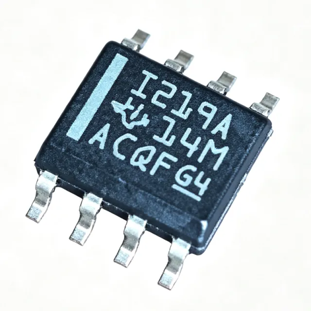
INA219AIDR - 26V 12-Bit I2C Power Monitor | Texas Instruments
Teilenummer: INA219AIDR ✓ Aktiv| Menge | Stückpreis | Gesamt |
|---|---|---|
| 1 | $2.1 | $2,10 |
| 10 | $1.89 | $18,90 |
| 100 | $1.65 | $165,00 |
| 500 | $1.42 | $710,00 |
| 1.000 | $1.18 | $1.180,00 |
| 2.500 | $1.05 | $2.625,00 |
INA219AIDR Übersicht
A digital power monitor is an integrated circuit that measures current, voltage, and power in a system by sensing the voltage drop across a shunt resistor and the bus voltage, then converting these analog signals to digital values via an ADC and reporting them over a digital bus. It sits within the power management IC (PMIC) hierarchy, specifically under current/voltage/power monitoring ICs, which are essential for optimizing energy efficiency, protecting loads, and providing telemetry in battery-powered and industrial systems.
Key features include ±1% maximum current sense error (A grade), ±50µV maximum input offset voltage, ±0.5µV/°C offset drift, 16 programmable I2C addresses, and a programmable alert pin for overcurrent or undervoltage interrupts. The shunt voltage full-scale range is ±320mV at PGA gain/1 and the bus voltage range covers 0V to 26V. The I2C interface supports standard (100kHz), fast (400kHz), and high-speed (3.4MHz) modes, with multi-device bus sharing via address pins A0/A1.
Technically, the INA219AIDR uses a zero-drift chopper-stabilized front-end to minimize input offset and drift across -40°C to 125°C, eliminating the calibration burden typical of discrete current-sense amplifiers. The integrated multiplier combines shunt current and bus voltage to produce a 16-bit power reading in watts, with calibration registers that convert raw shunt voltage to engineering-unit amperes for the host MCU.
Typical applications include battery monitoring in smartphones and laptops, server/telecom power supply monitoring, solar MPPT current sensing, motor current monitoring in industrial drives, and maker/hobbyist energy-meter projects using Arduino or Raspberry Pi over I2C.
When designing with the INA219AIDR, place the shunt resistor in the high-side path and ensure the bus voltage stays within 0V to 26V. Decouple the supply pin with a 0.1µF ceramic capacitor close to the IC and keep I2C SDA/SCL traces short to minimize noise coupling. The ALERT pin can drive a host interrupt for immediate fault response.
This page synthesizes distributor pricing, drop-in alternatives, and practical design notes not found in the manufacturer datasheet.
Drop-in-Alternativen für INA219AIDR – gleiches Gehäuse, Pin-kompatibel. Bauteile mit anderem Gehäuse, die eine PCB-Überarbeitung erfordern, sind ausgeschlossen.
Varianten dieser Serie
Modelle derselben Serie, die drop-in-kompatibel sind mit INA219AIDR (gleiche Bauform und Footprint) – abweichend in Function, Package, ADC Resolution, Interface, Operating Temperature.
Schnellvergleichstool – Wählen Sie Alternativbauteile für den Direktvergleich:
INA219BIDR
✅ Drop-In✓ Auf Lager
$1.62 / Stück
Datenblatt ansehen →INA219AIDCNR
✅ Drop-In✓ Auf Lager
$1.15 / Stück
Datenblatt ansehen →INA219BIDR
✅ Drop-In✓ Auf Lager
$1.62 / Stück
Datenblatt ansehen →INA219AIDR Grenzwerte & elektrische Eigenschaften
| Funktion | Current/Power Monitor |
| Sensing Method | High-Side, Bidirectional |
| Input Voltage (V+) | 3 V to 5.5 V |
| Common-Mode Bus Voltage | 0 V to 26 V |
| Shunt Voltage Full-Scale (PGA=1) | ±320 mV |
| Bus Voltage Range | 0 V to 26 V |
| ADC Resolution | 12-bit (Shunt), 12-bit (Bus) |
| Current Sense Accuracy (A grade) | ±1% (max) |
| Input Offset Voltage | ±50 µV (max) |
| Input Offset Drift | ±0.5 µV/°C (max) |
| Versorgungsstrom | 1 mA (max, operating) |
| Schnittstelle | I2C / SMBus-compatible |
| I2C Address Options | 16 (A0, A1 pins) |
| I2C Modes | Standard 100 kHz, Fast 400 kHz, High-Speed 3.4 MHz |
| Alert/Comparator Pin | Yes, programmable threshold |
| Betriebstemperatur | -40°C to +125°C |
| Gehäuse | 8-SOIC (D) 3.90 mm |
| Montageart | Surface Mount |
| MSL-Level | 1 (unlimited) |
| RoHS-Status | Compliant |
INA219AIDR Pin-Konfiguration
| Pin 1 | A0 — I2C address select bit 0 |
| Pin 2 | A1 — I2C address select bit 1 |
| Pin 3 | GND — Ground |
| Pin 4 | VS — Bus voltage sense input (0-26V) |
| Pin 5 | IN+ — Shunt positive input (high side) |
| Pin 6 | IN- — Shunt negative input (load side) |
| Pin 7 | SDA — I2C data |
| Pin 8 | SCL — I2C clock |
Typische Anwendungen
INA219AIDR ist geeignet für 6 Anwendungs: Battery Monitoring in Portable Electronics, Server and Telecom Power Supply Monitoring, Solar MPPT Current Sensing, Motor Current Monitoring in Industrial Drives, Maker / Arduino Energy Meter Projects, USB-C Power Delivery Monitoring.
Battery Monitoring in Portable Electronics
The INA219AIDR is well suited to battery monitoring in smartphones, laptops, and power banks because its bidirectional ±320mV shunt sensing and signed 12-bit output directly report charge and discharge currents. With ±1% accuracy (A grade) and ±50µV input offset, it captures milliamp-range currents without manual calibration. Placed in the high-side path between the battery pack and the system load, it returns current, bus voltage, and calculated power over I2C to the host power-management MCU. Unlike a discrete op-amp + ADC solution, the integrated zero-drift chopper amplifier eliminates offset drift across -40°C to +125°C, improving runtime-remaining estimation accuracy in temperature-varying environments.
Empfohlen
Server and Telecom Power Supply Monitoring
The INA219AIDR fits 12V and 24V server/telecom rails because its 0V to 26V common-mode range covers the bus directly without level shifting, and its I2C interface daisy-chains 16 addresses on a single SMBus for multi-rail telemetry. Drawing only 1mA from a 3.3V or 5V auxiliary supply, it adds negligible load. Each INA219AIDR reports shunt current, bus voltage, and computed power to the baseboard management controller (BMC), enabling load balancing and fault detection. Compared to a hall-effect sensor, the shunt-based design provides superior DC accuracy and faster response to load transients in datacenter applications.
Empfohlen
Solar MPPT Current Sensing
The INA219AIDR is a good fit for solar photovoltaic current sensing at the panel or string level because its high-side sensing keeps the shunt at ground potential, eliminating ground-loop issues common in low-side solar monitors. Bidirectional capability also supports battery-coupled PV systems where current flows both ways depending on sun and load. The 0-26V common-mode range covers most 12V and 24V battery banks, and the integrated 16-bit power calculation provides instant watts data for MPPT algorithms. Recommended placement is between the PV positive terminal and the charge controller input with a calibrated 10mΩ or 20mΩ shunt.
Empfohlen
Motor Current Monitoring in Industrial Drives
The INA219AIDR is suitable for motor current monitoring in industrial drives and robotics where accurate phase-current telemetry enables closed-loop torque control and fault detection. With 12-bit resolution and programmable PGA gains (/1 to /8), it accommodates shunt values from 1mΩ to 100mΩ across motor current ranges of 1A to 50A. The high-side placement avoids the ground-referencing problems of low-side current sensing, which can corrupt PWM gate-drive signals. The ALERT pin provides hardware-interrupt capability for overcurrent shutdown, while the I2C interface simplifies wiring to the industrial MCU or PLC over long cable runs.
Empfohlen
Maker / Arduino Energy Meter Projects
The INA219AIDR is widely adopted in hobbyist energy-meter projects built on Arduino, Raspberry Pi, and ESP32 because its I2C interface integrates with standard libraries (Adafruit_INA219) and requires only two signal wires plus power. The breakout boards from Adafruit and SparkFun typically include a 0.1Ω shunt and pull-up resistors, providing ±3.2A full-scale measurements out of the box. The bidirectional sensing tracks both charging and discharging in battery-powered IoT nodes, while the ±1% accuracy is more than adequate for home energy monitoring. Compared to a CT clamp + ADC approach, the INA219AIDR solution is smaller, cheaper, and supports DC loads.
Empfohlen
USB-C Power Delivery Monitoring
The INA219AIDR is appropriate for monitoring USB-C Power Delivery (PD) current and voltage on the VBUS line because its 0-26V common-mode range covers the 5V, 9V, 15V, and 20V PD profiles, and its ±320mV shunt input handles 5A at 20mΩ or 3A at 100mΩ. Bidirectional sensing tracks both sourcing and sinking in DRP (Dual Role Port) applications. The I2C interface pairs naturally with PD controller MCUs, while the ALERT pin can trigger host interrupts on overcurrent events. For 100W (5A) USB-PD, use a calibrated 20mΩ shunt to stay within the 320mV PGA/1 range; for lower-power ports, a 100mΩ shunt maximizes ADC resolution.
Empfohlen
Zusammenfassung der empfohlenen Produkte
Technische Referenzdaten für INA219AIDR – Vergleich, Designhinweise und Compliance-Informationen.
Auswahlhilfe
Vergleich mit Alternativen
| Parameter | Dieses Produkt | INA219BIDR | INA219AID | INA219BID |
|---|---|---|---|---|
| Package | 8-SOIC (D) | 8-SOIC (D) - same | 8-SOIC (D) - same | 8-SOIC (D) - same |
| Brand | Texas Instruments | Texas Instruments | Texas Instruments | Texas Instruments |
| Current Sense Accuracy | ±1% (max) | ±0.5% (max, B grade) | ±1% (max, same die) | ±0.5% (max, B grade) |
| Common-Mode Bus Voltage | 0 V to 26 V | 0 V to 26 V | 0 V to 26 V | 0 V to 26 V |
| Shunt Voltage Full-Scale | ±320 mV | ±320 mV | ±320 mV | ±320 mV |
| Input Offset (max) | ±50 µV | ±50 µV | ±50 µV | ±50 µV |
| Interface | I2C / SMBus | I2C / SMBus | I2C / SMBus | I2C / SMBus |
| Operating Temperature | -40°C to +125°C | -40°C to +125°C | -40°C to +125°C | -40°C to +125°C |
| Shipping Packaging | Tape & Reel (R suffix) | Tape & Reel (R suffix) | Tube | Tube |
| Lifecycle Status | Active | Active | Active | Active |
Wichtigste Unterscheidungsmerkmale
- B-grade accuracy available in same footprint (vs. INA219BIDR)
- True bidirectional current sensing with signed output (vs. INA180 (analog-output current-sense amplifier family))
- Integrated 16-bit power calculation engine (vs. Discrete op-amp + external ADC approach)
Designhinweise
Place a 0.1µF ceramic decoupling capacitor as close as possible to the V+ pin (pin 8) to suppress supply noise. The shunt resistor should be a low-inductance type (e.g., 4-terminal Kelvin sense resistor) to avoid parasitic voltage drops in high-current paths. Keep the IN+ and IN- traces as a differential pair routed directly to the shunt sense pads to minimize thermocouple effects and ground loops. The exposed die pad (if present) should be soldered to a copper pour for thermal relief, though the part typically dissipates <100mW and does not require a heatsink.
Do not exceed the absolute maximum common-mode voltage of 26V on the IN+/IN- pins or VS pin; transients above this can permanently damage the IC. Do not operate V+ below 3V - the I2C logic levels become undefined and the host MCU cannot reliably communicate. The I2C bus requires external pull-up resistors (typically 2.2kΩ to 10kΩ depending on bus capacitance); the INA219AIDR does not include internal pull-ups. A0 and A1 must not be left floating - tie each to GND, V+, SDA, or SCL to set a valid address.
Estimated: at a 1mA bias current and 26V common-mode, the INA219AIDR draws negligible power from the monitored bus. For best ADC noise performance, average multiple conversions using the configuration register (e.g., 128-sample average at 532µs conversion time reduces noise to ~1µVrms at PGA/8). Place the shunt near the load rather than near the source to capture actual load current and avoid IR drops in PCB traces adding error. When monitoring high dI/dt loads (e.g., motor PWM), add an RC filter (100Ω + 100nF) at IN+/IN- to suppress switching transients that may exceed the input common-mode rating.
Compliance-Informationen
RoHS and REACH compliant per TI product page. Not AEC-Q100 qualified - for automotive applications consider INA219-Q1 variants. Lead-free and halogen-free per TI materials declaration.







