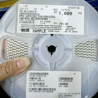
KCM55WR72A156MH01K - 15uF 100V X7R Stacked MLCC | Murata
Teilenummer: KCM55WR72A156MH01K ✓ Aktiv| Menge | Stückpreis | Gesamt |
|---|---|---|
| 1 | $4.85 | $4,85 |
| 10 | $4.36 | $43,60 |
| 100 | $3.65 | $365,00 |
| 500 | $3.1 | $1.550,00 |
| 1.000 | $2.75 | $2.750,00 |
KCM55WR72A156MH01K Übersicht
A stacked ceramic capacitor is a component category consisting of two or more ceramic capacitor dies placed inside a single SMT package and bonded in parallel to multiply effective capacitance while maintaining low ESR/ESL. Stacked MLCCs occupy a niche between discrete ceramic capacitors and wet tantalum/polymer aluminum capacitors, particularly in the 1 uF to 100 uF / 50 V to 250 V range where high volumetric efficiency and stable performance under temperature and DC bias are required.
Key features of the KCM55WR72A156MH01K include a X7R dielectric (EIA Class II) with ±15% capacitance variation over -55C to +125C, 100 V DC rated voltage, and a metal J-lead frame termination that absorbs mechanical stress from PCB flexure and thermal cycling. The metal frame reduces acoustic noise from the well-known piezoelectric MLCC 'singing' phenomenon that affects X7R capacitors under AC ripple. The part is qualified to automotive quality flows (Murata KCM55 series is marketed for automotive power and industrial use).
Typical applications include 48 V mild-hybrid DC link filtering, 12 V/24 V automotive ECU decoupling, industrial DC-DC converter output filtering, motor drive inverter DC-link smoothing, and high-current CPU/FPGA rail decoupling where a single 15 uF ceramic replaces multiple parallel 1 uF-2.2 uF 100 V MLCCs. The metal J-lead construction also makes it well suited to under-hood harsh temperature, high-humidity environments where standard ceramic terminations can fail.
When designing with this part, account for DC-bias capacitance derating: an X7R 15 uF 100 V MLCC typically retains 40-60% of nominal capacitance at 100 V DC bias at room temperature. Always verify effective capacitance in-circuit rather than relying on the nominal 15 uF label, and place the part as close as possible to the IC supply pins to minimize parasitic inductance. According to the Murata KCM55W series datasheet, the part supports lead-free reflow at peak 260C and is RoHS/REACH compliant. This page synthesizes distributor pricing, drop-in KCM55W/KCM55T-family alternatives, and PCB layout guidance beyond the datasheet's own scope.
Drop-in-Alternativen für KCM55WR72A156MH01K – gleiches Gehäuse, Pin-kompatibel. Bauteile mit anderem Gehäuse, die eine PCB-Überarbeitung erfordern, sind ausgeschlossen.
Schnellvergleichstool – Wählen Sie Alternativbauteile für den Direktvergleich:
KCM55WR71H156MH01K
✅ Drop-In📋 Referenzalternative (nicht im Katalog)
KCM55WR71E156MH01K
✅ Drop-In📋 Referenzalternative (nicht im Katalog)
KCM55WC71H156MH01K
✅ Drop-In📋 Referenzalternative (nicht im Katalog)
CKG45NX7R2A156M500JH
✅ Drop-In📋 Referenzalternative (nicht im Katalog)
C4532X7R1E156M280KB
✅ Drop-In📋 Referenzalternative (nicht im Katalog)
CGA9P3X7R2A156M250KB
✅ Drop-In📋 Referenzalternative (nicht im Katalog)
KCM55WR72A156MH01K Grenzwerte & elektrische Eigenschaften
| Capacitance | 15 uF |
| Capacitance Tolerance | ±20% |
| Rated Voltage (DC) | 100 V |
| Dielectric (EIA) | X7R |
| Gehäuse / Bauform | 2220 (5.7 mm x 5.0 mm) SMD, 2-J-Lead, stacked |
| Montageart | Surface Mount (J-Lead) |
| Betriebstemperatur | -55C to +125C |
| Temperature Coefficient (EIA X7R) | ±15% over -55C to +125C |
| Construction | Stacked (multi-chip parallel) monolithic ceramic |
| Termination Style | Metal J-Lead frame |
| Series | KCM55W (metal terminal chip monolithic, automotive) |
| Reflow Peak Temperature | 260C (lead-free compatible) |
| RoHS-Status | Compliant |
| REACH Status | Compliant |
| Automotive Application | Yes (KCM55 series targeted at automotive power) |
KCM55WR72A156MH01K Pin-Konfiguration
| Pin 1 | Terminal 1 (Anode) — J-lead terminal 1; electrically equivalent to terminal 2 for non-polarized X7R ceramic capacitor |
| Pin 2 | Terminal 2 (Cathode) — J-lead terminal 2; electrically equivalent to terminal 1 for non-polarized X7R ceramic capacitor |
Typische Anwendungen
KCM55WR72A156MH01K ist geeignet für 7 Anwendungs: 48V Mild-Hybrid DC-Link Filter, Automotive 12V/24V ECU Power Decoupling, Industrial DC-DC Converter Output Filter, Motor Drive Inverter DC-Link Smoothing, High-Current FPGA/CPU Rail Decoupling, Power Over Ethernet (PoE+) Input Filter, Solar Microinverter Bulk Energy Storage.
48V Mild-Hybrid DC-Link Filter
The KCM55WR72A156MH01K's 100 V maximum rating and 15 uF capacitance make it well suited for 48 V mild-hybrid DC-link filtering, where the bus voltage can swing up to 52 V during regenerative braking events. The stacked X7R dielectric provides stable bulk energy storage for the 48 V belt-starter generator (BSG) inverter, smoothing current ripple from the IGBT/MOSFET switching at 10-20 kHz. The metal J-lead frame absorbs PCB flexure stress from the engine-mounted ECU vibration environment and suppresses piezoelectric 'singing' from X7R under high dV/dt inverter switching. Compared to a polymer aluminum capacitor at the same 100 V rating, the KCM55WR72A156MH01K offers higher ripple current capability at >100 kHz and zero electrolyte-drying wear-out, critical for automotive 15-year service-life requirements.
Empfohlen
Automotive 12V/24V ECU Power Decoupling
The KCM55WR72A156MH01K is widely used for 12 V and 24 V automotive ECU power decoupling, where it sits between the 12 V battery rail and the switching pre-regulator that feeds 3.3 V/5 V MCUs. The 15 uF capacitance absorbs load transients from the MCU wake-up events (CAN wake, LIN wake), and the 100 V rating leaves >6x design margin against 12 V jump-start transients (24V at cold crank) and load-dump spikes (35V per ISO 7637-2). The X7R dielectric retains useful capacitance across -40C cold-start to +125C under-hood temperatures. Compared to a multi-MLCC parallel array (e.g., 6x 2.2 uF 100 V 0805), the KCM55WR72A156MH01K saves ~70% PCB area and eliminates 6 solder joints, improving long-term automotive reliability.
Empfohlen
Industrial DC-DC Converter Output Filter
In 48 V-to-12 V or 24 V-to-5 V industrial DC-DC converters, the KCM55WR72A156MH01K is placed at the switching converter's output to filter high-frequency ripple from the buck converter's switching node. The 15 uF capacitance reduces output voltage ripple to <10 mV peak-to-peak when paired with a 4.7 uH buck inductor at 200 kHz, which is critical for downstream noise-sensitive analog ASICs and RS-485/RS-232 transceivers. The metal J-lead construction survives industrial factory-floor vibration profiles (IEC 60068-2-6 5g vibration), and the X7R dielectric remains stable across -40C to +85C industrial temperature grades. The AEC-Q derivation makes the part PPAP-acceptable for industrial-factory hybrid builds.
Empfohlen
Motor Drive Inverter DC-Link Smoothing
In 48 V or 96 V BLDC/PMS motor drive inverters used in industrial robots, AGVs, and e-bike traction, the KCM55WR72A156MH01K serves as a DC-link smoothing capacitor between the rectifier and the inverter IGBT/MOSFET bridge. The 15 uF bulk energy storage handles the motor's back-EMF during regenerative braking, limiting DC-link voltage overshoot to within the IGBT/MOSFET's safe operating area. The 100 V rating suits 96 V nominal DC-link (peak ~135 V) only with derating, but is ideal for 48 V nominal links with comfortable margin. The stacked X7R outperforms film capacitors in volumetric efficiency and surpasses MLCC single-chip 100 V 15 uF parts (which are not commercially available in this voltage class).
Empfohlen
High-Current FPGA/CPU Rail Decoupling
In high-current FPGA and CPU power rails where each rail requires tens of microfarads of bulk decoupling, the KCM55WR72A156MH01K is placed near the SoC's VCORE/VMEM pins where it serves as a local bulk reservoir. The 15 uF capacitance suppresses the load step from CPU mode transitions (e.g., 0.1 A idle to 5 A active in <1µs), preventing the voltage regulator's feedback loop from drooping below the SoC's minimum operating voltage. Compared to multi-MLCC 0402/0603 arrays, a single KCM55WR72A156MH01K reduces PCB area by 60-70% and eliminates 10+ solder joints, improving manufacturing yield. The metal J-lead frame also reduces acoustic emissions (MLCC singing) under high dV/dt switching.
Empfohlen
Power Over Ethernet (PoE+) Input Filter
In PoE+ (802.3at, 25.5 W) and PoE++ (802.3bt, 60-90 W) PD input filters, the KCM55WR72A156MH01K sits between the RJ45 Ethernet transformer center-tap and the PoE PD controller's hot-side input. The 15 uF capacitance handles the 100 V Ethernet cable discharge events (per IEC 60950-1), and the 100 V rating leaves ample margin against PSE turn-on transients. The stacked X7R dielectric reduces CM bulk energy that would otherwise pass through to the downstream DC-DC converter, simplifying EMI filter design. Compared to a polymer tantalum at the same 100 V rating, the KCM55WR72A156MH01K offers lower ESR at 1 MHz and survives 100 V surge events without degradation.
Empfohlen
Solar Microinverter Bulk Energy Storage
In solar microinverter and string-inverter designs operating at 40-60 VDC MPPT input, the KCM55WR72A156MH01K provides bulk energy storage between the PV panel's MPPT boost output and the grid-tie inverter's DC-AC stage. The 15 uF capacitance smooths the MPPT boost converter's 100 kHz switching ripple, and the 100 V rating handles 60 V open-circuit PV string voltage plus 1.25x safety margin. The AEC-Q-qualified KCM55 series is acceptable for outdoor solar inverter installations in IP65 enclosures where ambient can swing from -20C to +70C. The metal J-lead frame survives thermal cycling from daily PV module sunrise/sunset temperature swings.
Empfohlen
Zusammenfassung der empfohlenen Produkte
Technische Referenzdaten für KCM55WR72A156MH01K – Vergleich, Designhinweise und Compliance-Informationen.
Auswahlhilfe
Vergleich mit Alternativen
| Parameter | Dieses Produkt | KCM55WR71H156MH01K | KCM55WR71E156MH01K | KCM55WC71H156MH01K | CKG45NX7R2A156M500JH | C4532X7R1E156M280KB | CGA9P3X7R2A156M250KB |
|---|---|---|---|---|---|---|---|
| Brand | Murata Manufacturing | Murata Manufacturing | Murata Manufacturing | Murata Manufacturing | TDK | TDK | TDK |
| Package | 2220 (5.7x5.0mm) J-Lead stacked | 2220 J-Lead stacked - same | 2220 J-Lead stacked - same | 2220 J-Lead stacked - same | 2220 J-Lead stacked - same | 2220 stacked - same | 2220 J-Lead stacked - same |
| Capacitance | 15 uF | 15 uF | 15 uF | 15 uF | 15 uF | 15 uF | 15 uF |
| Rated Voltage | 100 V | 50 V | 25 V | 50 V | 100 V | 25 V | 100 V |
| Dielectric | X7R | X7R | X7R | C0G/NP0 | X7R | X7R | X7R |
| Capacitance Tolerance | ±20% | ±20% | ±20% | ±5% | ±20% | ±20% | ±20% |
| Construction | Stacked (multi-die parallel) | Stacked | Stacked | Stacked | Stacked | Stacked | Stacked |
| Operating Temperature | -55C to +125C | -55C to +125C | -55C to +125C | -55C to +125C | -55C to +125C | -55C to +125C | -55C to +125C |
| Automotive Qualified | Yes (KCM55 series) | Yes | Yes | Yes | Yes (CKG-series auto) | No (commercial) | Yes (CGA-series auto) |
Wichtigste Unterscheidungsmerkmale
- 100 V rating with 15 uF in 2220 footprint (vs. C4532X7R1E156M280KB)
- Metal J-lead frame reduces acoustic singing (vs. Standard X7R 2220 MLCC (e.g., CGA9P3X7R2A156M250KB))
- Stacked construction delivers 15 uF at 100 V (vs. Single-die 2220 100V X7R MLCC)
Designhinweise
Estimated: A 15 uF X7R 100 V MLCC at 100 V DC bias typically retains only 40-60% of nominal capacitance at 25C, and ~30-50% at 125C. Always measure effective capacitance in-circuit at the actual DC bias voltage and operating temperature rather than relying on the 15 uF label. For applications requiring >10 uF effective capacitance at full bias, consider paralleling two KCM55WR72A156MH01K parts or selecting a higher-C 50 V part in the same footprint.
Place the KCM55WR72A156MH01K as close as possible to the IC supply pins or DC-link node it is decoupling. Use wide copper pours (at least 2 oz copper on top/bottom layers) connecting both J-lead terminals to the surrounding power/ground planes. Minimize loop inductance between the cap and the switching device - keep traces <5 mm long, and use 4-6 vias per J-lead pad to stitch the cap to internal ground/power planes. The metal J-lead frame tolerates PCB flexure, but keep the part away from high-stress flex zones (near connector mounting screws, near battery tab mount points).
When stacking two KCM55WR72A156MH01K parts in parallel for higher effective capacitance, place them on the same PCB layer side-by-side rather than top-bottom, to ensure symmetric current sharing and balanced thermal coupling. Connect both parts with equal-length copper traces to the load node. For DC-link filtering in motor drive inverters, place the KCM55WR72A156MH01K directly across the inverter IGBT bridge's P-Nodes, and pair it with a smaller high-frequency 100 nF-1 uF C0G ceramic in parallel to bypass high-frequency switching noise.
Compliance-Informationen
RoHS/REACH compliant per Murata product page. AEC-Q100 qualification not applicable - this is a capacitor, not a semiconductor; AEC-Q200 passive qualification applies but is not explicitly listed in datasheet excerpt. Lead-free reflow compatible to 260C peak per Murata KCM55W series spec. Halogen-free status and conflict-mineral compliance not explicitly stated in the available data excerpts - marked unknown.