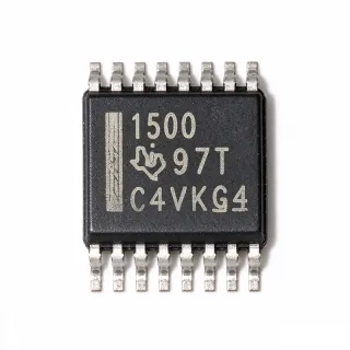
MAX3221CDB - 250kbps RS-232 Transceiver | Texas Instruments
Teilenummer: MAX3221CDB ✓ AktivMAX3221CDB Übersicht
An RS-232 transceiver is an interface IC that converts logic-level signals between a host or controller and a RS-232 serial link. The MAX3221 belongs to the line-driver and line-receiver hierarchy within interface ICs and interface transceivers. It is useful where a compact embedded system must communicate with legacy serial equipment, industrial controllers, service consoles, or other RS-232 endpoints without using a higher-voltage ±5 V supply rail.
Key electrical features include a 3 V to 5.5 V supply range, operation at up to 250 kbps, one full-duplex driver, one full-duplex receiver, and ±15 kV ESD protection. The integrated dual charge-pump circuit provides the RS-232 level-shifting function needed by the line driver, while the receiver provides inversion and thresholding appropriate for noisy serial environments. A dedicated receiver-enable input supports controlled receiver operation in systems where the serial line must be disabled temporarily.
The MAX3221 architecture is intended for low-voltage systems that cannot conveniently support a traditional RS-232 supply. Operating the charge-pump and transceiver from 3 V to 5.5 V reduces system-voltage requirements, while the single-channel structure avoids the channel count and pin requirements of multi-driver RS-232 devices. The 16-pin SSOP package is suitable for compact industrial, communications, instrumentation, and embedded-control equipment.
Typical applications include RS-232 configuration ports, programmable-instrument control, industrial serial adapters, point-of-sale equipment, and maintenance interfaces. Its 250 kbps capability is more than adequate for many legacy control protocols, while the receiver enable function is useful in systems that share, isolate, or periodically disconnect a serial port.
A key design consideration is that the external RS-232 connector, cable, and ground path determine much of the real-world ESD and noise immunity. Place the transceiver close to the connector, route the interface ground appropriately, and use the datasheet-recommended charge-pump capacitor and driver-load arrangements to preserve signal integrity.
This page consolidates the device specifications, pin-compatible family comparisons, application guidance, and design cautions needed to evaluate the MAX3221CDB alongside other single-channel RS-232 transceivers.
Drop-in-Alternativen für MAX3221CDB – gleiches Gehäuse, Pin-kompatibel. Bauteile mit anderem Gehäuse, die eine PCB-Überarbeitung erfordern, sind ausgeschlossen.
MAX3221EIDB
✅ Drop-In📋 Referenzalternative (nicht im Katalog)
MAX3221ECDB
✅ Drop-In📋 Referenzalternative (nicht im Katalog)
MAX3221ECAE+T
✅ Drop-In📋 Referenzalternative (nicht im Katalog)
MAX3221IDBR
✅ Drop-In📋 Referenzalternative (nicht im Katalog)
SP3220CA
✅ Drop-In📋 Referenzalternative (nicht im Katalog)
MAX3221CDB Technische Daten
| Product Type | Single-channel RS-232 line driver/receiver transceiver |
| Supply Voltage Range | 3 V to 5.5 V |
| Maximum Data Rate | 250 kbps |
| Number of Drivers | 1 |
| Number of Receivers | 1 |
| Duplex Mode | Full duplex |
| ESD Protection | ±15 kV |
| Charge-Pump Architecture | Dual charge-pump circuit |
| Receiver Control | Dedicated enable pin |
| Gehäuse | 16-pin SSOP |
| Montageart | Surface mount |
| Minimum Operating Temperature | -40 °C |
| Operating Supply Current | 1 mA |
MAX3221CDB 16-pin ssop Pinbelegungsleitfaden
Pinbelegung für MAX3221CDB (16-pin ssop-Gehäuse). Pin-Nummerierung, Funktionen und Anschlussdiagramme sind im Herstellerdatenblatt definiert. Entnehmen Sie diesem den genauen Footprint und Lötrichtlinien.

Keine detaillierten Pinbelegungsdaten verfügbar für MAX3221CDB.
Siehe die Datenblatt für die vollständige Pin-Konfiguration.
Typische Anwendungen
MAX3221CDB ist geeignet für 6 Anwendungs: Legacy RS-232 Configuration Port, Programmable Instrument Control, Industrial Serial Adapter, Point-of-Sale Terminal Interface, Embedded Service Console, Data Acquisition Controller.
Legacy RS-232 Configuration Port
The MAX3221CDB fits legacy configuration ports because it combines a 250 kbps single-channel driver and receiver with operation from 3 V to 5.5 V. Place the transceiver between a host UART and a DB9 or terminal connector, using its dual charge-pump circuit to provide the required RS-232 levels. The dedicated receiver-enable input can disable the receiver when the port is idle or isolated. Its ±15 kV ESD protection on the serial connection pins strengthens the external interface, while the 16-pin SSOP package keeps the implementation compact. Check connector pin numbering, signal-ground routing, and cable length before layout release.
Empfohlen
Programmable Instrument Control
The MAX3221CDB is suitable for connecting a controller to programmable test and measurement equipment that retains a legacy RS-232 command interface. Its 250 kbps maximum data rate accommodates many serial instrument protocols, while the 3 V to 5.5 V supply range simplifies integration with contemporary embedded controllers. The receiver-enable function can support controlled bus participation, although the device does not provide galvanic isolation. Locate the transceiver near the external connector, provide a low-impedance ground return, and follow the manufacturer charge-pump capacitor values. Verify the instrument's logic levels, connector sex, and handshake requirements during schematic review.
Empfohlen
Industrial Serial Adapter
The MAX3221CDB supports compact industrial serial adapters that translate modern controller UART signals into RS-232 for older machinery. Its one-driver, one-receiver arrangement fits point-to-point full-duplex links, and its ±15 kV ESD protection is useful when the adapter connects to service connectors exposed to charged cables or maintenance events. Operating from 3 V to 5.5 V allows the interface to share a system rail with embedded logic. The design should include connector-side protection and grounding consistent with the application environment, while avoiding assumptions that the IC rating replaces enclosure-level surge protection. Validate command timing and cable limitations before field deployment.
Empfohlen
Point-of-Sale Terminal Interface
The MAX3221CDB can bridge a compact point-of-sale controller to a legacy serial peripheral when the equipment still uses an RS-232 command channel. Its 250 kbps capability is appropriate for short control exchanges, and its 3 V to 5.5 V operation supports compact embedded designs. The single-channel topology avoids unnecessary line-driver and receiver circuits when only one full-duplex port is needed. Place the IC close to the connector, keep the ground return adjacent to the signal trace where practical, and observe the datasheet capacitor-selection guidance. Confirm voltage levels and connector pin assignments because legacy point-of-sale equipment may use custom cable wiring.
Empfohlen
Embedded Service Console
The MAX3221CDB is useful in embedded equipment that offers a service or maintenance console through an RS-232 connector. The receiver-enable pin provides a way to control whether the interface listens on the line, while the 250 kbps rate supports diagnostic commands, firmware logs, and configuration transfer. Its low-voltage operation is compatible with embedded processors and reduces the need for a separate RS-232 power rail. Design the connector path with effective ground continuity and controlled cable routing, and apply the manufacturer charge-pump capacitor configuration for dependable line-driver amplitude. Keep the service interface physically accessible but consider a temporary disable strategy for production security.
Empfohlen
Data Acquisition Controller
The MAX3221CDB can connect a data-acquisition controller to legacy RS-232 instruments or laboratory adapters. At up to 250 kbps, it supports command traffic and moderate serial data transfers, while its full-duplex driver and receiver arrangement permits simultaneous request and response signaling when the protocol and wiring support it. The 3 V to 5.5 V supply range simplifies integration with embedded control hardware, but the interface does not provide isolation. For lab equipment, use a protective ground strategy and verify cable length and grounding to prevent ground-loop problems. Place the transceiver near the connector and follow the official application circuit for charge-pump components.
Empfohlen
Zusammenfassung der empfohlenen Produkte
Technische Referenzdaten für MAX3221CDB – Vergleich, Designhinweise und Compliance-Informationen.
Auswahlhilfe
Vergleich mit Alternativen
| Parameter | Dieses Produkt | MAX3221EIDB | MAX3221ECDB | MAX3221ECAE+T | MAX3221IDBR | SP3220CA |
|---|---|---|---|---|---|---|
| Brand | Texas Instruments | Texas Instruments | Texas Instruments | Texas Instruments | Texas Instruments | Sipex |
| Package | SSOP-16 | SSOP-16 | SSOP-16 | SSOP-16 | SSOP-16 | SSOP-16 |
| Supply Voltage Range | 3 V to 5.5 V | 3 V to 5.5 V | 3 V to 5.5 V | 3 V to 5.5 V | 3 V to 5.5 V | 3 V to 5.5 V |
| Number of Drivers | 1 | 1 | 1 | 1 | 1 | 1 |
| Number of Receivers | 1 | 1 | 1 | 1 | 1 | 1 |
Wichtigste Unterscheidungsmerkmale
- Single-channel interface with controlled receiver operation (vs. MAX3232IPW)
- 250 kbps operation from a 3 V to 5.5 V supply (vs. SP3220CA)
- Dedicated receiver-enable control (vs. MAX3221EIDB)
- External-interface ESD protection (vs. SP3220CA)
Designhinweise
Place the MAX3221CDB close to the external RS-232 connector. Keep the receiver and driver connections short, provide a direct interface-ground return, and avoid routing serial signals beneath or parallel to noisy switching nodes. The manufacturer application circuit should be used for charge-pump capacitor placement because incorrect capacitor values or long loop lengths can reduce driver amplitude and degrade edge behavior.
Do not treat logic-level UART signals as RS-232 signals. The line driver and receiver perform voltage conversion, inverting logic and thresholding as required by the RS-232 interface. Confirm the connector assignment for TXD, RXD, ground, and any hardware handshake lines. A swapped TXD/RXD connection can appear to communicate during a loopback test but fail on an external device.
The ±15 kV ESD rating applies to the designated serial connection pins, but the complete connector still needs a deliberate ground and cable strategy. Use low-impedance ground returns, keep external protection paths away from sensitive logic, and evaluate whether additional surge or isolation is required for long cables. The MAX3221CDB does not provide galvanic isolation.
Decouple the 3 V to 5.5 V supply close to the device and follow the Texas Instruments datasheet for the recommended charge-pump capacitors and bypass capacitance. Check startup behavior with the receiver-enable state defined, since a floating or incorrectly driven control input can affect the operating state. Include the transceiver and external capacitor losses when sizing a low-power supply.
Compliance-Informationen
The product page and family description do not state RoHS, REACH, lead-free, halogen-free, or conflict-minerals status. AEC-Q100 is not applicable because this is a general-purpose interface IC rather than an automotive-qualified device in the stated ordering information.