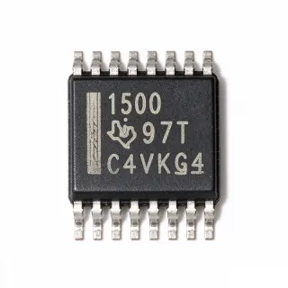
PCA9557DB - 8-Bit I2C I/O Expander | Texas Instruments
Teilenummer: PCA9557DB ✓ AktivPCA9557DB Übersicht
An I/O expander is a type of interface IC that connects a serial bus to additional digital lines. The PCA9557DB belongs to the I2C/SMBus GPIO expander family, combining a serial interface controller, configuration registers, and eight quasi-bidirectional I/O ports. Its I2C and SMBus compatibility places it within the broader interface-IC and embedded-control hierarchy, where it can reduce the GPIO requirements of a microcontroller or processor.
The PCA9557DB supports a 2.3 V to 5.5 V supply range, allowing use with both 3.3 V and 5 V systems. Its serial interface operates up to 400 kHz, while eight I/O pins provide flexible control of LEDs, logic inputs, or external interface signals. Dedicated configuration registers allow software to identify input or output direction, while the reset and configuration registers support deterministic peripheral initialization and bus management.
The device communicates through serial clock and serial data lines, with address selection provided by hardware pins. The SSOP package is a compact surface-mount option, and the verified distributor information identifies the DB ordering variant as a 16-pin SSOP measuring approximately 0.209 inches, or 5.30 mm, in width. Because this is a general-purpose interface device rather than a power semiconductor, a safe operating area chart is not applicable.
Typical uses include low-power MCU systems, industrial control modules, sensor-hub boards, LED indicators, and small embedded platforms requiring eight additional digital lines. The PCA9557DB is particularly useful when conserving controller pins is more important than high-speed parallel GPIO operation. Because the serial interface is shared with other bus devices, address configuration, pull-up requirements, and software initialization must be coordinated during board design.
Designers should confirm the exact pin functions and electrical limits in the manufacturer datasheet before layout. Bus pull-ups, input thresholds, power sequencing, and the states of I/O pins during reset require careful review. Software should configure each port direction and initial output value before enabling the associated external circuitry to prevent unintended switching.
This page consolidates verified manufacturer and distributor information, documents missing electrical parameters transparently, and identifies only same-package drop-in candidates supported by the supplied cross-reference evidence. It also adds application guidance and engineering checks that are not available from a distributor listing alone.
Drop-in-Alternativen für PCA9557DB – gleiches Gehäuse, Pin-kompatibel. Bauteile mit anderem Gehäuse, die eine PCB-Überarbeitung erfordern, sind ausgeschlossen.
Varianten dieser Serie
Modelle derselben Serie, die drop-in-kompatibel sind mit PCA9557DB (gleiche Bauform und Footprint) – abweichend in Package.
PCA9557D
✅ Drop-InPreis auf Anfrage
Datenblatt ansehen →PCA9557DB Technische Daten
| Device Type | 8-bit low-power I2C/SMBus I/O expander |
| Number of I/O Ports | 8 |
| Betriebsversorgungsspannung | 2.3 V to 5.5 V |
| Maximum Serial Bus Frequency | 400 kHz |
| Serial Interface | I2C and SMBus |
| Gehäuse | 16-pin SSOP |
| Package Width | 0.209 inch (5.30 mm) |
| Register Features | Reset and configuration registers |
| Montageart | Surface mount |
PCA9557DB 0.209 inch (5.30 mm) Pinbelegungsleitfaden
Pinbelegung für PCA9557DB (0.209 inch (5.30 mm)-Gehäuse). Pin-Nummerierung, Funktionen und Anschlussdiagramme sind im Herstellerdatenblatt definiert. Entnehmen Sie diesem den genauen Footprint und Lötrichtlinien.

Keine detaillierten Pinbelegungsdaten verfügbar für PCA9557DB.
Siehe die Datenblatt für die vollständige Pin-Konfiguration.
Typische Anwendungen
PCA9557DB ist geeignet für 6 Anwendungs: Low-Power Microcontroller GPIO Expansion, Industrial Control and Automation Module, LED and Indicator Control Panel, Sensor Hub and Discrete Input Interface, Embedded Communication Equipment, Battery-Powered Portable Device.
Low-Power Microcontroller GPIO Expansion
The PCA9557DB is suitable when a microcontroller or low-power embedded controller needs eight additional digital lines without dedicating eight host GPIO pins. Its eight I/O ports are reached through the I2C/SMBus interface, which operates up to 400 kHz, while the 2.3 V to 5.5 V supply range supports both 3.3 V and 5 V designs. The device can control indicators or read discrete logic states when the host lacks enough direct pins. Firmware should configure each port direction and its initial value before enabling attached circuitry, and the bus must include appropriate pull-ups.
Empfohlen
Industrial Control and Automation Module
The PCA9557DB can expand a small industrial controller with eight software-addressable lines for relay-control inputs, panel signals, or discrete sensor interfacing. Its 2.3 V to 5.5 V operating range allows deployment in systems built around 3.3 V or 5 V control electronics, and the 400 kHz bus rate is suitable for ordinary control updates. Because the I/O expansion is serial, switching activity must be coordinated in firmware. Review the datasheet for output-current and electrical-state limits, and use pull-up resistors selected for the actual bus capacitance and voltage level.
Empfohlen
LED and Indicator Control Panel
The PCA9557DB provides eight additional lines for LED status indicators, relay indicators, or segmented low-rate annunciators in an instrument or control panel. Its I2C/SMBus interface reduces the number of direct host-controller pins needed for repetitive indicator functions, while software can change port direction and output values through the configuration registers. The 400 kHz maximum interface rate is more than sufficient for human-interface status updates. Design the circuitry so reset states do not create misleading or unsafe indications, and initialize outputs before enabling connected LEDs or drivers.
Empfohlen
Sensor Hub and Discrete Input Interface
The PCA9557DB can collect slow-changing discrete states such as door contacts, mode selectors, presence indicators, or digital sensor outputs while keeping the host serial bus as the communication backbone. Eight configurable I/O lines provide more capacity than a typical application-specific GPIO, and the 2.3 V to 5.5 V range allows integration with mixed-voltage sensor conditioning. Firmware should debounce mechanical inputs and avoid relying on timing assumptions outside the official electrical limits. The I2C address must also be checked against every other expander on the shared bus.
Empfohlen
Embedded Communication Equipment
The PCA9557DB is useful in compact communication equipment that needs extra control or status lines but has limited host GPIO availability. Its I2C/SMBus interface at up to 400 kHz can coexist with other low-speed peripherals when addresses and pull-ups are planned correctly, while the broad 2.3 V to 5.5 V range simplifies integration across voltage domains. Common uses include link-enable, reset, fault, or indicator signals. Review the reset behavior and configure the pins before external hardware becomes active so power-up sequencing does not produce unintended network or module states.
Empfohlen
Battery-Powered Portable Device
The PCA9557DB can reduce the pin count of a battery-powered portable system that needs several low-rate digital controls while operating from a 2.3 V to 5.5 V supply. Serial I/O expansion leaves more host pins available for sensing or power management, although the device's exact quiescent current is not included in the supplied verified data and must be checked before making a battery-life claim. Use the lowest appropriate bus activity rate, retain the host in its intended sleep state, and ensure the expander remains compatible with the system's power-gating and brownout behavior.
Empfohlen
Zusammenfassung der empfohlenen Produkte
Technische Referenzdaten für PCA9557DB – Vergleich, Designhinweise und Compliance-Informationen.
Auswahlhilfe
Vergleich mit Alternativen
| Parameter | Dieses Produkt | PCA9557D |
|---|---|---|
| Package | 16-pin SSOP | 16-pin SSOP |
| Brand | Texas Instruments | Texas Instruments |
| I/O Count | 8 bits | 8 bits |
| Operating Supply Voltage | 2.3 V to 5.5 V | 2.3 V to 5.5 V |
| Maximum Bus Frequency | 400 kHz | 400 kHz |
| Serial Interface | I2C and SMBus | I2C and SMBus |
| Reset and Configuration Registers | Supported | Supported |
Wichtigste Unterscheidungsmerkmale
- Eight I/O lines with serial bus access (vs. PCA9557D)
- Compatibility with common embedded supply levels (vs. PCA9557D)
- Moderate-speed shared-bus operation (vs. PCA9557D)
- Software-managed initialization (vs. PCA9557D)
Designhinweise
Route SDA and SCL as a compact, controlled bus and place pull-up resistors at locations approved by the system architecture, commonly close to the master or distributed according to the complete bus topology. Calculate the effective resistance against the actual bus capacitance rather than copying a generic value. Keep the PCA9557DB away from noisy power-conversion loops, use a continuous ground reference, and place its decoupling capacitor close to the supply and ground pins in accordance with the manufacturer layout guidance.
Do not assume that two parts labeled as I/O expanders are drop-in compatible. The supplied comparisons mention TCA9554ADBR and PCF8574ATD, but their pin counts, address schemes, reset polarity, interrupt behavior, and package assignments may differ from PCA9557DB. A replacement must match the 16-pin SSOP footprint and every connected signal, including address selection, reset, supply, ground, and all eight I/O lines. Review the official datasheet and test the substitute before production release.
Configure output values and port directions immediately after reset and before enabling downstream circuits. This sequencing prevents an external latch, relay driver, or indicator from receiving an unintended state. Confirm the supply ramp requirements, I2C behavior during power transitions, and reset polarity from the manufacturer datasheet. If the expander shares a bus with a powered-off device, check bus back-power behavior and ensure pull-ups do not hold the bus at an unintended level.
Compliance-Informationen
The supplied verified search results identify the manufacturer, function, electrical range, bus speed, package, and ordering information but do not state specific compliance declarations. Values are therefore left unknown rather than inferred.